 Add Surface Specific Cover ( Modeling )
Tool summary :

The edit windows of concrete members to which this component has been added have a "
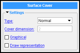
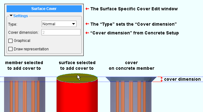
Settings " leaf containing the options shown here. You can edit cover settings under that leaf. Or, to open up this window (shown at left), double-click a cover while the " Selection filter " is set to ' Custom Components ''.

-
To begin adding the component, you can click the Add Surface Specific Cover icon instead of doing steps 2 and 3 of the procedure that follows. The icon can be found in the command group ' Model--Component ' for Toolbar Configuration (classic) or Ribbon Editor (lightning).
- To add the custom component: 1 ) In Modeling , select an appropriate concrete member (slab, beam, column, etc.). 2 ) Add Component . 3 ) On the custom component selection list, choose " Surface Specific Cover " as the custom component you want to add. 4 ) Select a surface for the concrete member that you selected in step 1. 5 ) The Surface Specific Cover Edit window opens. Enter the settings that you want, then press " OK " to close the window. 6 ) If User and Site Options > Modeling > " Automatically process after modeling operation " is set to ' Process and create solids ', the cover is generated immediately. If not, the cover will be generated the next time the member undergoes Process and Create Solids .
- If you use in-tool selection -- that is, select the member after selecting " Surface Specific Cover " as the custom component you want to add -- only concrete and CMU walls, elevations walls, concrete slabs, and pad footings will be selectable.
- See, on this page, to add, edit or delete the surface specific cover custom component .
Also see :
|
- Modeling (where custom components can be added)
- Concrete Cover Surfaces ( Home > Project Settings > Job > Concrete > )
- Custom components (topic)
- Explode Component (to reduce the custom component to its constituent materials)
- Component Selection Tool (to search for custom components of a selected type)
- Model Tree (to find custom components and select them for deletion, editing, etc.)
concrete | model > component > | add component | top
 To edit or delete a Surface Specific Cover custom component :

To edit a Surface Specific Cover custom component or review its settings, you can find the member it is added to and open its edit window. The component's settings will be contained in that window in a section named [ Surface Cover ] . To edit a Surface Specific Cover custom component without opening a member edit window, use the Model Tree . You also can use the Selection Filter toolbar item to select the ' Custom Components ' filter and double-click the cover. The Component Selection Tool can also be used to edit (and find) custom components.
To delete a Surface Specific Cover custom component: 1 ) Use the Component Selection Tool and select the component in the concrete member. Or , select the component in the Model Tree . 2 ) Press the Delete key (or choose Edit > Delete ). 3 ) Manual invocation of Process and Create Solids is required only if User and Site Options > Modeling > " Automatically process after modeling operation " is not set to a choice that makes create solids take place automatically.
In the Model Tree , the Surface Specific Cover custom component is listed as Surface Specific Cover @ ( [ x, y, z ] ) when " View By " is set to ' Member piecemark ' or ' Member number '. The Surface Specific Cover component is listed under its member, after that member's connection components ( Left End and Right End ), and before that member's submaterials.
concrete | model > component > | add component | top
 Surface Specific Cover custom component settings :
------  Settings ------
Type: The " Description " of a cover entered on a line of the table in the Concrete Cover Surfaces window. The " Type " is, by default, set to the ' ![]() Default ' cover that is specified on the Concrete Cover Surfaces window. You can switch the " Type " to any cover that has been defined on the Surface Specific Cover Edit window.
Default ' cover that is specified on the Concrete Cover Surfaces window. You can switch the " Type " to any cover that has been defined on the Surface Specific Cover Edit window.
Cover dimension: A read-only dimension (in the primary dimension " Units " or other units ). It reports the " Cover dimension " that is entered in Concrete Cover Surfaces for the " Type " of cover you have selected. Changing the " Type " updates the reported " Cover dimension " from setup.

|
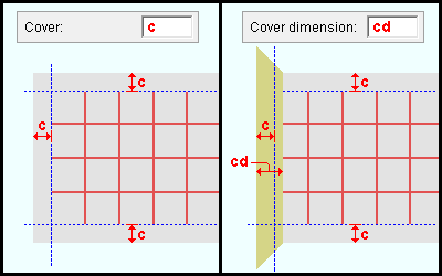
Example : A Rebar System whose cover is ' c ' is added to a concrete slab (left). A Surface Specific Cover is then added to the end of the slab (right). On that slab, the rebar end stops at ' cd ' where the end " Cover dimension " is greater than ' c ' . |
Note: If this dimension is greater than the cover setting a Rebar System component, the " Cover dimension " setting will override the " Cover " dimension.
|
A Surface Specific Cover component is automatically set to "
Graphical " whenever you make graphical changes to the cover. For example, when you apply the Cut Plane operation on the cover. This stops the component from being changed during Process and Create Solids . Click here for more information.
Instead of allowing the component to be made "
Graphical ," you may wish to Explode Component .
If this box is checked (
), a visual representation of the surface cover will be shown in the model and on the member detail. The cover will be listed in the bill of material.
If the box is not checked (
), no visual representation of the surface cover will be shown. The cover will not be listed in the bill of material.


