 Add Welded Wire Mesh Slab Reinforcement ( Modeling )
Tool summary :
- Can be added to a concrete slab member. The welded wire mesh becomes a component of the member to which it is added.

The custom component models the application of "welded wire mesh" or "welded wire fabric," and gives you control over the spacing and the diameter of the wire.
Also see :
- Modeling (where custom components can be added)
- Custom components (topic)
- Copy Component (to copy the component to another concrete slab)
- Move Component (to move the component to another concrete slab)
- Explode Component (to reduce the component to its constituent materials and welds)
- Component Selection Tool (to search for custom components of a selected type)
- Model Tree (to find custom components and select them for deletion, editing, etc.)
- The Rebar System and Rebar Area Layout components also provide concrete slab reinforcement.
concrete | model > component > | add component | top
 To add, delete, or edit Welded Wire Mesh Slab Reinforcement :
To add the custom component: 1 ) In Modeling , select a concrete slab. 2 ) Choose Model > Component > Add . 3 ) On the custom component selection list, choose " Welded Wire Mesh Slab Reinforcement " as the custom component you want to add. 4 ) The Welded Wire Mesh Slab Reinforcement Edit window opens. Enter the settings that you want, then press " OK " to close the window. 5 ) If User and Site Options > Modeling > " Automatically process after modeling operation " is set to ' Process and create solids ', the reinforcement will be generated immediately. If not, it will be generated in the member the next time the member undergoes Process and Create Solids .
| Tip: If you use in-tool selection -- that is, select the member after selecting " Welded Wire Mesh Slab Reinforcement " as the custom component you want to add -- only concrete slabs will be selectable. |
To delete a Welded Wire Mesh Slab Reinforcement custom component: 1 ) Use the Component Selection Tool and select the component in the slab. Or , select the component in the Model Tree . 2 ) Press the Delete key (or choose Edit > Delete ). 3 ) Process and Create Solids if User and Site Options > Modeling > " Automatically process after modeling operation " is not set to a choice that automatically creates solids.
In the Model Tree , the Welded Wire Mesh Slab Reinforcement custom component is listed as Welded wire mesh slab reinforcement @ ( [ x, y, z ] ) when " View By " is set to ' Member piecemark ' or ' Member number '. The Welded Wire Mesh Slab Reinforcement component is listed under its member, after that member's connection components ( Left End and Right End ), and before that member's submaterials.
To edit a Welded Wire Mesh Slab Reinforcement custom component or review its settings, you can find the member it is added to and open its edit window. The component's settings will be contained in that window in a section named [ Welded Wire Mesh Slab Reinforcement ] . To edit a Welded Wire Mesh Slab Reinforcement custom component without opening a member edit window, use the Model Tree . You also can use the Selection Filter widget to select the ' Custom Components ' filter and double-click the mesh to edit it. The Component Selection Tool can also be used to edit (and find) custom components.
concrete | model > component > | add component | top
 Welded Wire Mesh Slab Reinforcement custom component settings :
VIDEO 
With respect to " Graphical ," all custom components work much the same. This video demonstrates how it works on a Beam Stiffeners - Beam component
A Welded Wire Mesh Slab Reinforcement component is automatically set to "
Graphical " whenever you make graphical changes to its material. For example, when you Edit Material or perform a Cut On Plane operation on the component's material. This stops the component from being changed during Process and Create Solids . Click here for more information. Instead of allowing the component to be made "
Graphical ," you may wish to Explode Component .
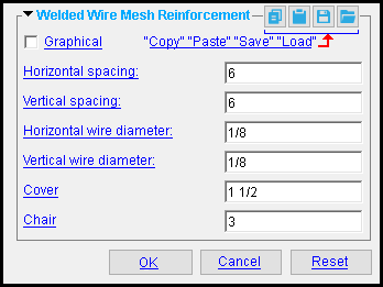
Horizontal spacing: A distance (in the primary dimension " Units " or other units ). The wire and its spacing are not modelled. However, the " Horizontal spacing " can appear in reports made with Report Writer .
Vertical spacing: A distance (in the primary dimension " Units " or other units ). The wire and its spacing are not modelled. However, the " Vertical spacing " can appear in reports made with Report Writer .
Horizontal wire diameter: A distance (in the primary dimension " Units " or other units ). The wire and its spacing are not modelled. However, the " Horizontal wire diameter " can appear in reports made with Report Writer .
Vertical wire diameter: A distance (in the primary dimension " Units " or other units ). The wire and its spacing are not modelled. However, the " Vertical wire diameter " can appear in reports made with Report Writer .
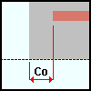
Cover: The distance (in the primary dimension " Units " or other units ) from the ends of the mesh to the edges of the concrete slab.

|
Co = Cover
|
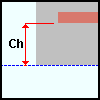
Chair: The distance (in the primary dimension " Units " or other units ) between the bottom of the mesh and the bottom of the concrete member.

|
Ch = Chair
|


