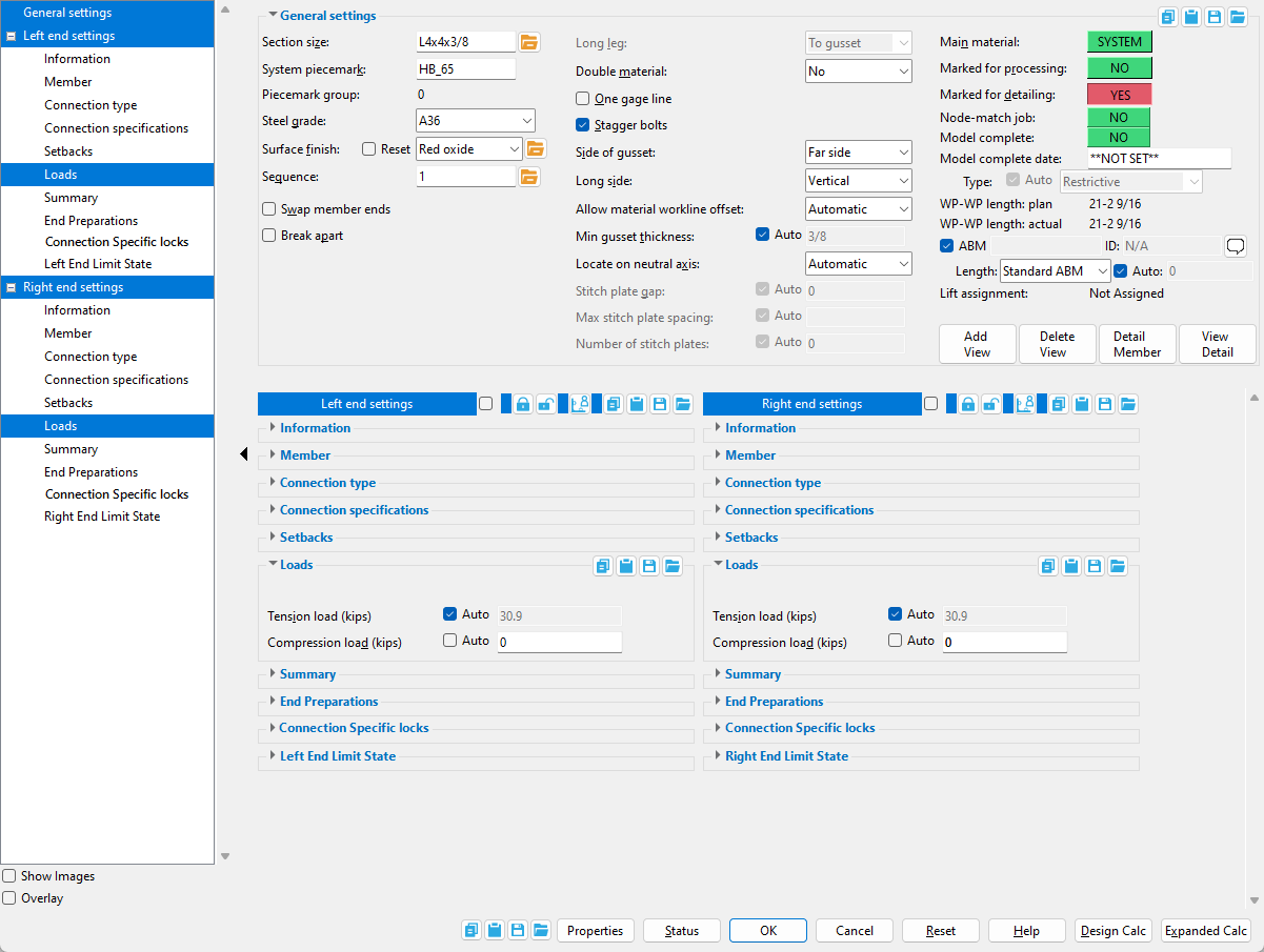
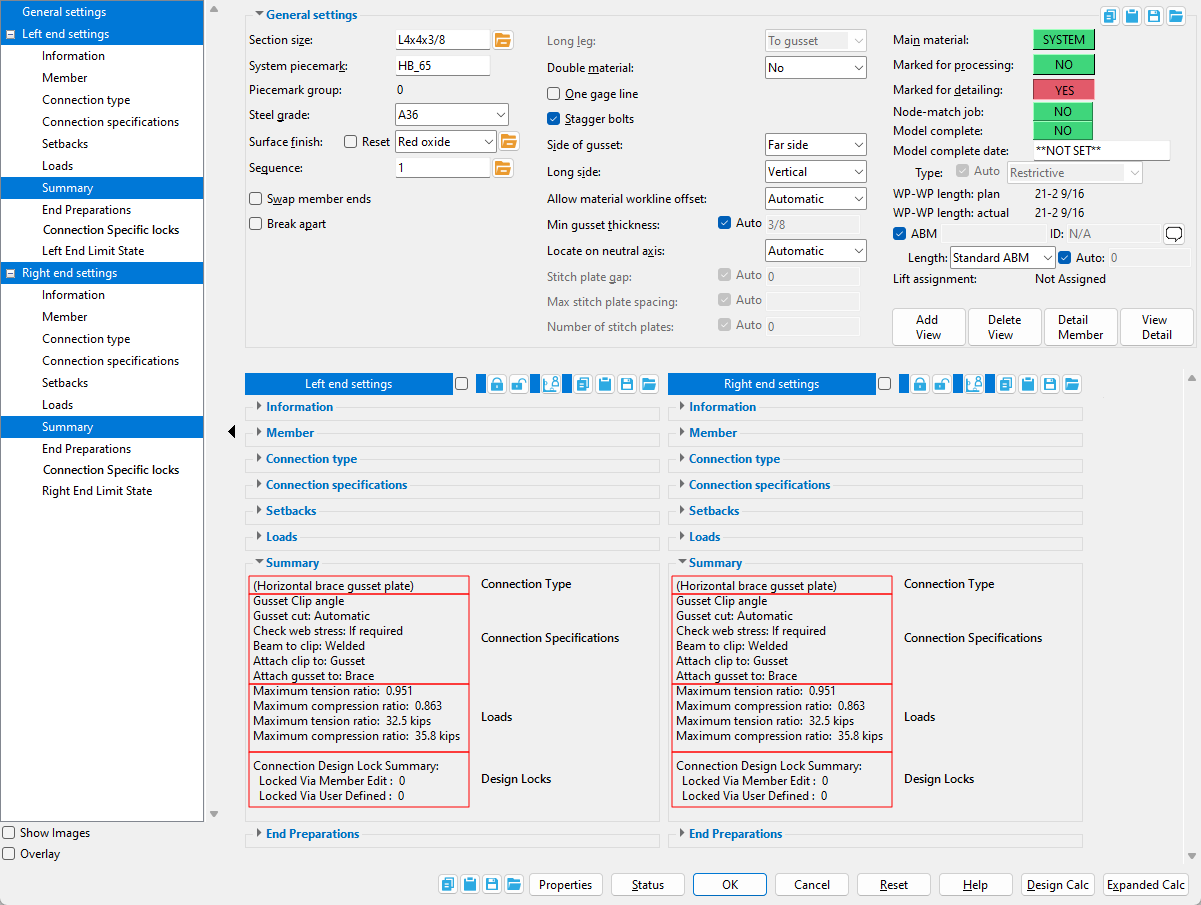
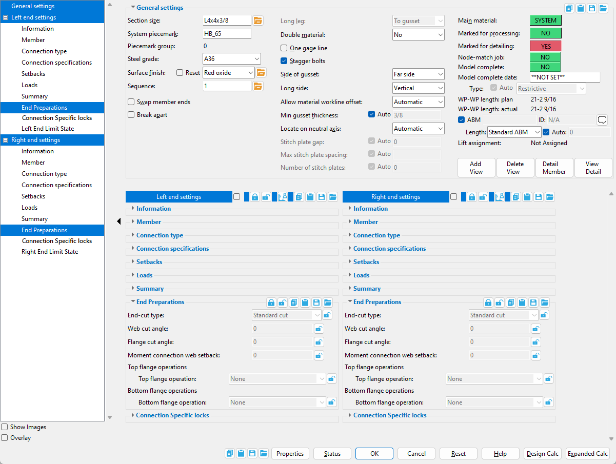
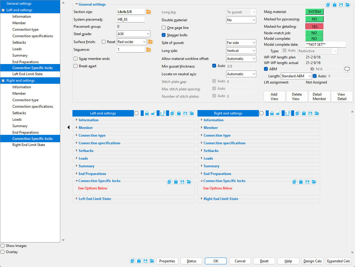
Horizontal Brace Edit
- General Overview
- Tips and Tricks
- Related Tools
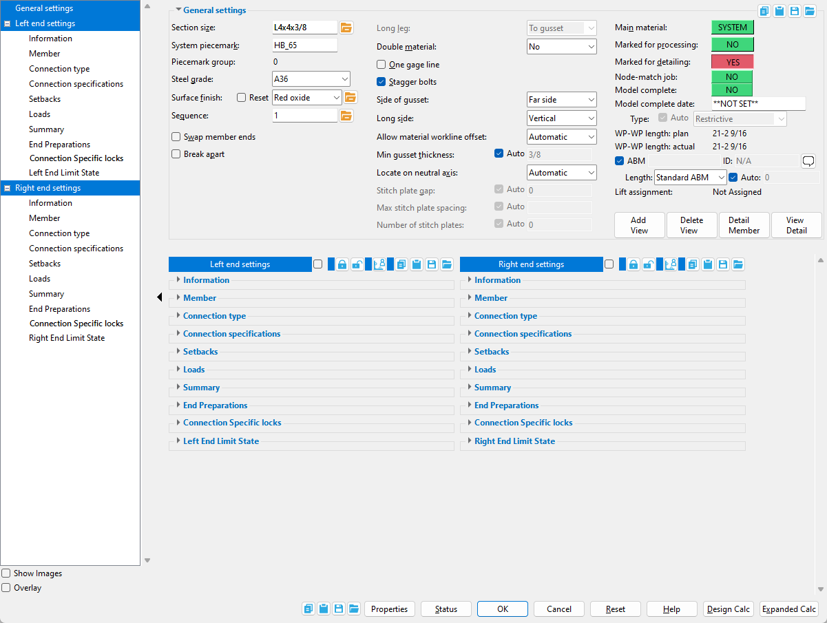
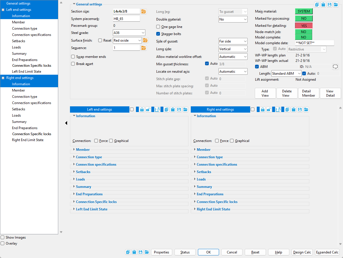
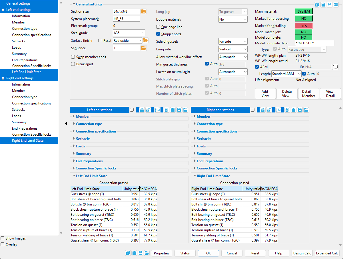
General Settings
" ![]() Show images " (when checked) displays drawings that depict the dimensions that are controlled by connection design locks.
Show images " (when checked) displays drawings that depict the dimensions that are controlled by connection design locks.
" ![]() Overlay " (when checked) displays one leaf at a time. When you select a leaf, either from the tree on the left or from inside the window itself, all other leaves collapse.
Overlay " (when checked) displays one leaf at a time. When you select a leaf, either from the tree on the left or from inside the window itself, all other leaves collapse.
![]() Copy, Paste, Save, Load buttons:
Copy, Paste, Save, Load buttons:
- The position of these "form" buttons on the window tells you what settings they apply to. Click here for more information.
- You can
 Copy the settings on this window, then
  Paste those settings to a different edit window of the same type.
- You can
 Save the settings on this window to a file stored in a global folder that is used by your current version of SDS2. Give the file a name that will help other users identify its purpose. You can
  Load a saved file to replace the settings on this window (except Piecemark) with the settings that are stored in the file you select.
- When editing multiple windows at the same time, Paste and Load replace mixed entries to a single field with a single entry. Copy and Save ignore fields with mixed entries, treating them as if they have no entry or do not exist.
Properties opens the Edit Properties window, on which you can make entries to custom properties. If your current Job was set to use a legacy flavor when it was created, the window that opens is named Custom Properties , not Edit Properties.
Tip: The Edit Properties window can also be used to read
Log entries or review or type
Tip: The Member Properties command is an alternative to this button. It opens the Edit Properties window directly, without your first having to open a member edit window.
Status opens the Member Status Review window, which can give you additional information about the member, and which you can use to enter status information or designate a member as an existing member.
Note: This button shows
if one or more Repeat check boxes on the Member Status Review window do not match the checked-unchecked state of same-named fields in User and Site Options > Site > Member status items to copy/repeat. On the Status Review window, the fields that do not match User and Site Options are plotted in red .
OK (or the Enter key) closes the edit window and saves any changes you have made on the window to the member file.
Solids on OK: If the appropriate choice is made to User and Site Options > Modeling > Automatically process after modeling operation, then this member will automatically be regenerated (Create Solids will take place) after your press OK. Otherwise, you will have to manually Process and Create Solids in order for changes you made on this window to be fully updated in the 3D model.
Change all: If you Edit Member (one member only) and make a change that potentially triggers the Do you want to change all ... dialog and the 3D model contains more than one member of the same type that has the same piecemark as the member you changed, a yes-no dialog opens. On it is the question, Do you want to change all (members with this piecemark). Press the Yes button to change all the members; press the No button to change only this member.
Cancel (or the Esc key or the ![]() button) closes the edit window without saving any changes that you have made. Cancel does not undo a Detail Member operation.
button) closes the edit window without saving any changes that you have made. Cancel does not undo a Detail Member operation.
Note: If you opened this window while adding a member, Cancel brings you back to the work point location step of adding a member.
Tip: Any time you use Edit Member just to review a member (and you do not want to set the defaults for to-be-added members), the best way to close this window is to Cancel.
Reset undoes any changes made since you opened this window.
Exception: Reset does not undo changes made using the Add View, Delete View, Detail Member, and View detail buttons.
Information
Member
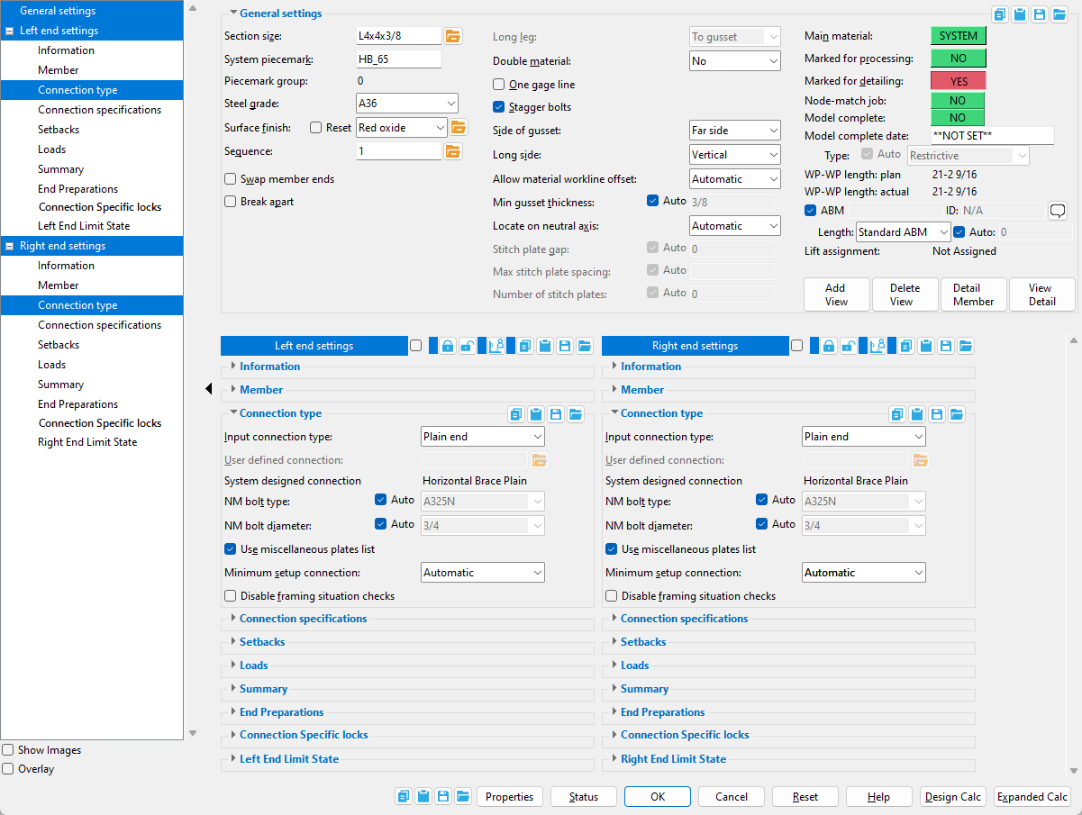
Connection Type
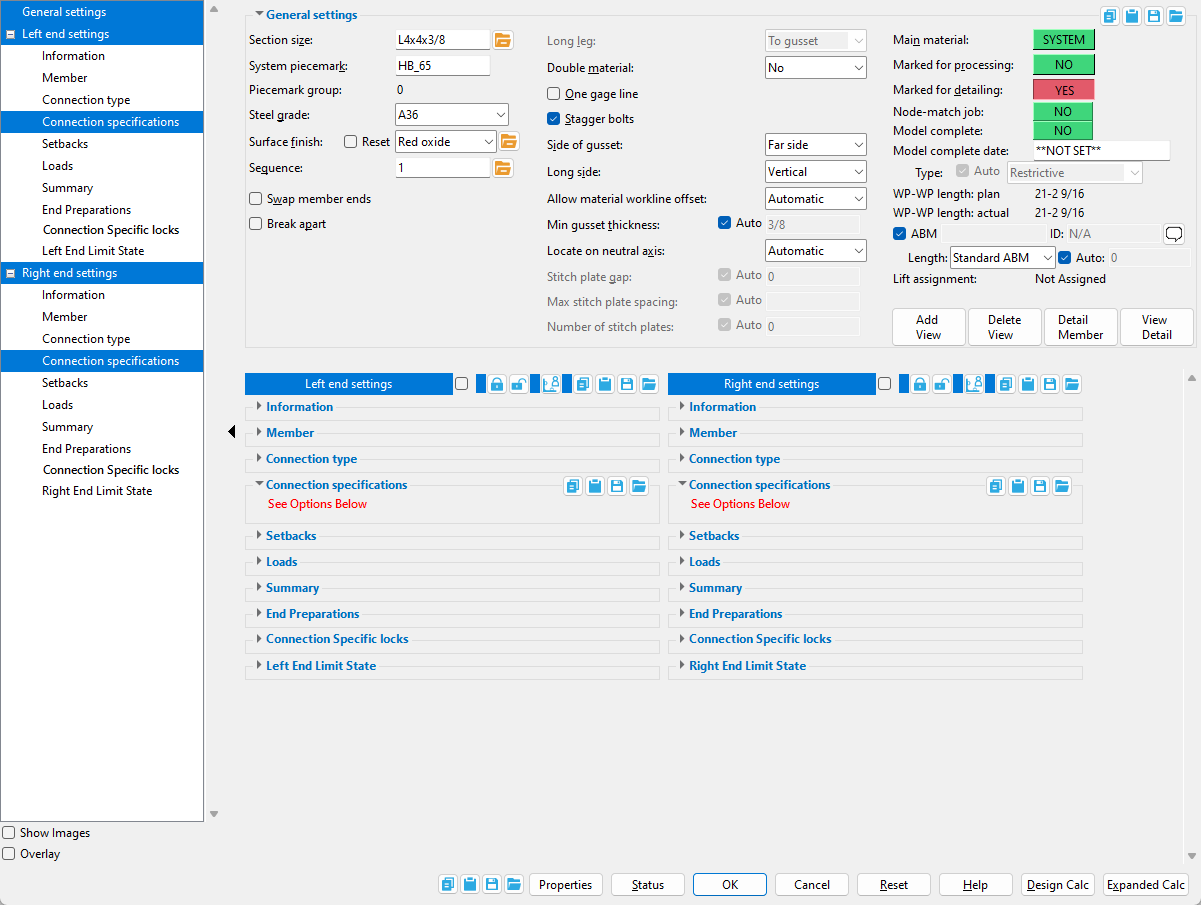
Connection Specifications
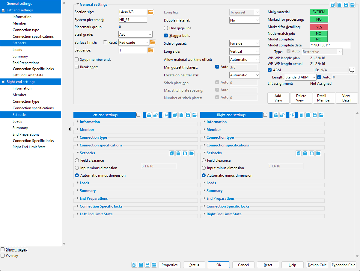
Setbacks
Loads
Summary
End Preparations
Connection Specific Locks
Horizontal Brace to a Beam's Top Flange
Horizontal Brace to a Beam's Web
Horizontal Brace Perpendicular to a Beam
Horizontal Brace 2- or 3-point bracing
Horizontal Brace Intersection (X bracing)
Horizontal Brace to Beam-Beam Corner
Horizontal Brace to Beam-Column-Beam Corner
Left/Right End Limit State
- Horizontal braces are system members.
- Horizontal braces may be input so they are perfectly horizontal or so that they slope up to 30 degrees from horizontal.
- To get to a view that is in the same plane as the beams, invoke Snap to Surface and click the top flange of one of the beams.
- Multi-member edit mixed entries are gray.
- "
 Show images " (when checked) displays drawings that depict the dimensions that are controlled by connection design locks.
 - " Overlay " (when checked) displays one leaf at a time. When you select a leaf, either from the tree on the left or from inside the window itself, all other leaves collapse.
- Custom component settings will appear on the Horizontal Brace Edit window only if a custom component has been added to the horizontal brace (using Model > Component > Add).
- To show / hide the member tree, select the expand and collapse arrow (
 ).
).
- Horizontal brace (index)
- Setup of horizontal braces (index)
- Connection guide (examples of horizontal brace connections)
- Brace Gusset Plates (setup of Add Horizontal Brace)
- Brace direction symbol (shows brace orientation is stick)
- Work lines (brace representation in stick)
- Member Copy (alternative to Add Horizontal Brace)
- Erase Member (to undo an Add Horizontal Brace)
- Edit Member (to modify an added brace)
- Move/Stretch Members (to stretch and/or move braces and other members)
- Move/Stretch Members, Include Material (same as Move/Stretch Members , but often better)
- Constructing the 3D model (topic)
- Failed connections (topic)