 Add Base Plate Shear Key ( Modeling )
Tool summary :
|
|
|
|
|
|
| To open the Base Plate Shear Key window again, after adding the shear key, you can double-click one of the Base Plate Shear Key materials or welds while the " Selection filter " is set to ' Default ' or ' All ' or ' Custom Components '.
The same controls that are shown here can also be accessed on the Column Edit window. The name of the " Component " section that controls the shear key is [ Base Plate Shear Key ] . |
||
Also see :
- Modeling (where custom components can be added)
- Custom components (topic)
- Base Plate Shear Key ( Home > Project Settings > Job > Component Plugin Defaults > )
- Copy Component (to copy a shear key to another member)
- Move Component (to move a shear key to another member)
- Explode Component (to reduce the custom component to its constituent materials and welds)
- Component Selection Tool (to search for custom components of a selected type)
- Model Tree (to find custom components and select them for deletion, editing, etc.)
To edit or delete the Base Plate Shear Key custom component :
- A Base Plate Shear Key custom component can be added to any column that has a user base plate.
Valid Column Material Types for User Base Plates 
Selecting a material or weld that is part of the Base Plate Shear Key custom component selects the entire component when the " Selection filter " is set to ' Default ' or ' All ' or ' Custom Components '
Base Plate Shear Key custom component settings :
![]() Graphical ---------------------------------------------------------------------------
Graphical ---------------------------------------------------------------------------
Graphical : ![]() or
or ![]() .
.
- A Base Plate Shear Key component is automatically set to "
 Graphical " whenever you make graphical changes to any of its materials or welds. For example, when you Edit Material or perform a cut operation on a Base Plate Shear Key material. Click here for more information.
- Instead of allowing the component to be made " Graphical ," you may wish to Explode Component .
![]() Locate --------------------------------------------------------------------------------
Locate --------------------------------------------------------------------------------
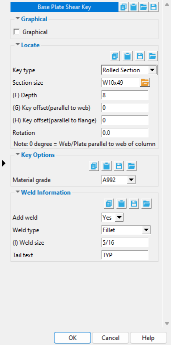
Key type: Rolled Section or Single Plate or Cross Plate or 3 Plate .
' Rolled Section ' gives you an option to set the " Section size " of the key to be a wide flange or HSS round or HSS rectangular section.
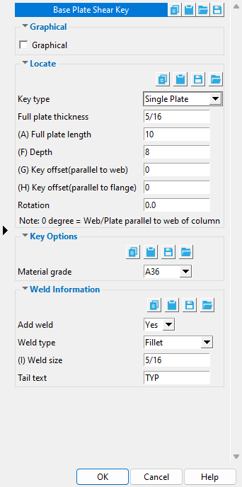
' Single Plate ' gives you options for setting the " Full plate thickness " and " Full plate length " of the single plate.
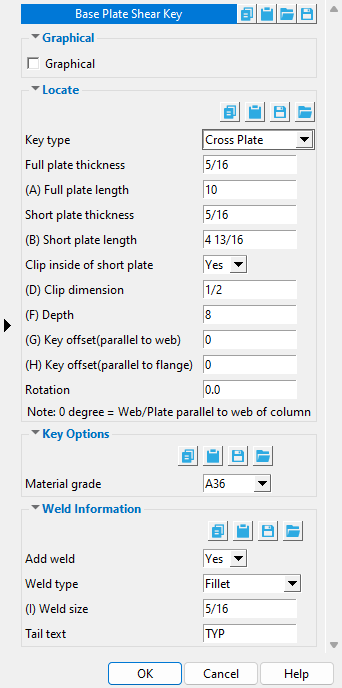
' Cross plate ' constructs a shear key that is composed of three plates, a full plate and two short plates. Options are available for setting the " Full plate thickness " and " Full plate length " and " Short plate length ." For the two short plates, there are options to " Clip inside of short plate " with a specified " Clip dimension. "
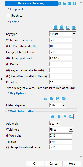
' 3 Plate ' constructs a shear key that is composed of three plates -- a web plate and two flange plates -- that are arranged in an "I" shape. Options are available for setting the " Web plate thickness " and " 3 Plate shape depth " and " Flange plate thickness " and " Flange plate width ."
Section size: a wide flange (W) or Pipe (HSS round or pipe) or HSS/TS (HSS rectangular or tube) section. This applies when ' Rolled Section ' is selected as the " Key type ."
Full plate thickness: The thickness (in the primary dimension " Units " or other units ) of the one plate that the shear key will be built from when ' Single Plate ' is selected as the " Key type ." This is also The " Material thickness " of the rectangular plate material that the single-plate shear key is made of.
Full plate length: The length (in the primary dimension " Units " or other units ) of the one plate that the shear key will be built from when ' Single Plate ' is selected as the " Key type ." This is also the " Order length " of the rectangular plate material that the single-plate shear key is made of.
Full plate thickness: The thickness (in the primary dimension " Units " or other units ) of the longest of the three plates that the shear key will be built from when ' Cross Plate ' is selected as the " Key type ."
Full plate length: The length (in the primary dimension " Units " or other units ) of the longest of the three plates that the shear key will be built from when ' Cross Plate ' is selected as the " Key type ." On the Rectangular Plate Material window, this will be the " Order length " of the plate.
Short plate length: The length (in the primary dimension " Units " or other units ) of each of the two short plates of the three plates that the shear key will be built from when ' Cross Plate ' is selected as the " Key type ." On the Rectangular Plate Material window, this will be the " Order length " of the plate.
Clip inside of short plate: Yes or No . This applies when ' Cross Plate ' is selected as the " Key type ." It allows you to clip the inside, top corner of each of the two short plates.
|
|

' Yes ' clips (at 45 degrees) the inside, top corner of each of the short plates. The inside corners of a short plate are the corners of the plate edge that butts to the full plate. The upper corner is the corner closest to the column base plate. The " Clip dimension " (below) sets the size of the clip cut.
' No ' instructs the Base Plate Shear Key custom component to not clip the corner.
Clip dimension: A distance (in the primary dimension " Units " or other units ). This applies when " Clip inside of short plate " is set to ' Yes '.
A distance of ' 0 ' ( zero ) instructs the Base Plate Shear Key custom component to not clip the corner.
A distance > ' 0 ' ( greater than zero ) applies a rectangular plate " Clip " operation to the inside, upper corner of each of the two short plates in the cross plate shear key. The " Clip length " dimension runs parallel with the length of the short plate. The " Clip depth " dimension runs parallel with the depth of the short plate. Both the " Clip length " and the " Clip depth " distances will match the " Clip dimension ," thus resulting in a 45 degree cut.
Web plate thickness: The thickness (in the primary dimension " Units " or other units ) of the longest of the three plates that the shear key will be built from when ' 3 Plate ' is selected as the " Key type ." This longest plate is referred to as the web plate.
3 Plate shape depth: The distance (in the primary dimension " Units " or other units ) between the outside faces of the flange plates. This applies when ' 3 Plate ' is selected as the " Key type ." The distance can also be measured as the length of the web plate plus the thicknesses of the two flange plates.
Flange plate thickness: The thickness (in the primary dimension " Units " or other units ) of each one of the two shorter plates that the 3-plate shear key will be built from when ' 3 Plate ' is selected as the " Key type ." The two shorter plates are the flange plates.
Flange plate width: The width (in the primary dimension " Units " or other units ) of each one of the two shorter plates that the 3-plate shear key will be built from when ' 3 Plate ' is selected as the " Key type ." The two shorter plates are the flange plates. The flange plate width is a horizontal dimension measured perpendicular to the length of the web plate. On the Rectangular Plate Material window, this will be the " Order length " of the plate.
Depth: The shear key extension beneath the base plate (in the primary dimension " Units " or other units ). This applies regardless of the " Key type ."
| Key type | How " Depth " affects the material. |
| Rolled Section | The " Depth " that is entered here sets the " Order length " of the rolled section material that is used to build the rolled-section shear key. |
| Single Plate | The " Depth " that is entered here sets the " Material width " of each of the rectangular plates that are used to build the single-plate or cross-plate or 3-plate shear key. |
| Cross Plate | |
| 3 Plate |
Key offset ( parallel to web ): The positive (+) or negative (-) distance (in the primary dimension " Units " or other units ) that you want the center of the shear key to be offset from center of the column. The center of a column is its workline . This applies regardless of the " Key type ."
offset = 0 |
offset = 3 |
' 0 ' (zero) keeps the neutral axis of the shear key in alignment with the neutral axis of the column.
A positive (+) distance offsets the shear key in a direction parallel with the web of the shear key. If you are facing the near side of the column and the " Rotation " of the shear key is ' 0 ', the offset direction will be from the left flange of the column (face A) toward the right flange of the column (face C). The example above shows the results of entering ' 3 ' as the " Key offset (parallel to web) ."
A negative (-) distance offset the shear key in a direction opposite to the direction it would be offset if you had entered a positive distance. If you are facing the near side of the column and the " Rotation " of the shear key is ' 0 ', this direction will be from the right flange of the column (face C) toward the left flange of the column (face A).
What is the web of a shear key? The "web" of a rolled-section shear key is the web of the rolled section. The web of a single-plate shear key is the single plate. The web of a cross-plate shear key is the full plate. The web of a 3-plate shear key is the web plate.
Key offset ( parallel to flange ): The positive (+) or negative (-) distance (in the primary dimension " Units " or other units ) that you want the center of the shear key to be offset from center of the column. The center of a column is its workline . This applies regardless of the " Key type ."
offset = 0 |
offset = 3 |
' 0 ' (zero) keeps the neutral axis of the shear key in alignment with the neutral axis of the column.
A positive (+) distance offsets the shear key in a direction parallel with the flange of the shear key. If you are facing the near side of the column and the " Rotation " of the shear key is ' 0 ', the offset direction will be away from you, toward the far side of the column. The example above shows the results of entering ' 3 ' as the " Key offset (parallel to flange) ."
A negative (-) distance offset the shear key in a direction opposite to the direction the shear key would be offset if you had entered a positive distance. If you are facing the near side of the column and the " Rotation " of the shear key is ' 0 ', the offset direction will be toward you, toward the near side of the column.
What is "parallel with the flange" of a shear key? The flanges of a rolled-section shear key are the flanges of the rolled section. Parallel with the flange of a single-plate shear key is parallel with the thickness dimension of the single plate. Parallel with the flange of a cross-plate shear key is parallel with the thickness dimension of the full plate. The flanges of a 3-plate shear key are the flange plates.
Rotation: A number of degrees . This applies regardless of the " Key type ."
| rotation = 0 |
rotation = 90 |
' 0 ' degrees keeps the shear key in alignment with the column. For a rolled-section shear key, this means that the web of the shear key is in alignment with the web of the column. For a single-plate shear key, this means that the single plate is in alignment with the web of the column. For a cross-plate shear key, this means that the full plate is in alignment with the web of the column. For a 3-plate shear key, this means that the web plate is in alignment with the web of the column.
A positive (+) number of degrees rotates the shear key counterclockwise (assuming you are looking down at the shear key from the top of the column).
A negative (+) number of degrees rotates the shear key clockwise (assuming you are looking down at the shear key from the top of the column).
![]() Key Options ----------------------------------------------------------------------
Key Options ----------------------------------------------------------------------
Material grade: A36 or A572 or etc. When the " Key type " is ' Cross Plate ' or ' Single Plate ' or ' 3 Plate ', this is the " Steel grade " of the rectangular plate(s) that each shear key is built from. When the " Key type " is ' Rolled Section ', this is the " Steel grade " of the wide flange, HSS rectangular or HSS round section.
Setup: If the grade of steel you want is not shown on the list box (
), you can use Home > Project Settings > Job > Plate Grades or Wide Flange Grades or Pipe Grades or HSS / TS Grades to add it to the list.
![]() Weld Information ------------------------------------------------------------------
Weld Information ------------------------------------------------------------------
|
|
' Yes ' shop welds the key to the base plate. When the " Key type " is ' Cross Plate ' or ' 3 Plate ', choosing ' Yes ' also welds the plates together. As a result, 3D welds will appear in the model. After the column is auto detailed ( Detail Members ), the welds will be represented on the column detail with weld symbols .
' No ' instructs the Base Plate Shear Key custom component to not add welds.
Weld type: Fillet or Square groove or Bevel groove or V groove or J groove or U groove or Flare bevel groove or Flare V groove . This sets the weld " Type " on the Weld Edit window in Modeling as well as the weld " Type " for the weld symbol on the column detail.
| symbol | name | weld used for... |
|
|
fillet | General welding of material. |
|
|
square groove | Butt joints. |
|
|
bevel groove | General full penetration welding of material. |
|
|
V groove | Butt joints of thicker material. |
|
|
J groove | Special full penetration welding of material. |
|
|
U groove | Butt joints of thicker material. |
|
|
flare bevel groove | For a radiused surface to flat surface. |
|
|
flare V groove | For a radiused surface to radiused surface. |
Weld size: A distance (in the primary dimension " Units " or other units ) that indicates depth of preparation, size or strength of the weld. This sets the " Weld size " on the Weld Edit window in Modeling as well as the " Weld size " for the weld symbol on the column detail.
Tail text: blank or a text string . This sets the " Supplementary tail text " on the Weld Edit window in Modeling as well as the " Supplementary tail text " for the weld symbol on the column detail.
|
TYP is the tail text of this weld symbol. |
If this field is left ' blank ', a tail is not drawn on the weld symbol.
If a ' text string ' is entered, a tail with that character string as the tail text is drawn on the weld symbol.

