Section View
Tool summary :
- Cuts a section view on a member detail, submaterial detail or erection view drawing.
- When a new section view is added to a member detail, it is also added in Modeling and can be viewed in member isolation .
- Similarly, any new section view that you add to a submaterial can also be seen in material isolation's edit views mode .
- Adding a section view to an erection view drawing creates a new straight grid line (and associated erection view) in Modeling.
- See (on this page):
Also see :
Cutting an erection view on a member detail :
| VIDEO
|

|
View > Section View in the Drawing Editor can be used to add views to a detail. The views are also added in Modeling .
|
|
Section View can be used in the Drawing Editor on a member detail that has been Unshortened . It lets you create a new view of a member by locating two points. The resulting view is perpendicular to the two points and looks at the member in the direction of the arrowhead that appears as you move the mouse pointer (  ) to locate the second point. The two points also set the width of the section view and position the section arrows . The following instructions assume that you are using a 3-button mouse, that User and Site Options > General > " Point location target " is set to ' Fancy ', and that you use mouse bindings similar to those shown in these illustrations. Before you begin, you may want to Unshorten . Or you can Unshorten in step 2. Also, you may want to add construction lines so that there are INCL points for locating the boundaries of the section view.

|
1 . Invoke Section View .
|
|
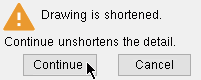
2 . This message appears only if you did not Unshorten already. Press " Continue " to Unshorten , or press " Cancel " if you don't want to go on.
|
|
3 . The status line prompts, " Select view from which to cut new view ." Place the mouse pointer ( ) anywhere in the view you want, then left-click ( Select ).
|
|
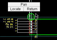
4 . Place the mouse pointer ( ) so the point location target snaps to a point defining one boundary of the section view, then left-click ( Locate ). INCL is the Locate option used in this example.
|
|
5 . The arrowhead that appears as you move the mouse pointer ( ) shows the direction that the view will face. Left-click ( Locate ) when the target is where you want the other boundary of the section view.
|
|
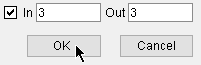
6 . Set the depth checking " In " and " Out " so that the proper perspective is shown in the section view.
|
|
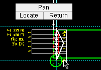
7 . The section view appears, and FRPT becomes the active Locate option. Move the view to where you want it, then left-click ( Locate ).
|
|
8 . The section view is now where you located it and is also in Member Isolation in Modeling (even if you do not Save ). If you auto detail this member again, the view will remain a part of the detail.
|
Note 1: To invoke Section View , choose View > Section View , or use a keyboard shortcut (if one has been set up), or click the icon pictured above (if it has been placed on your ribbon).
Note 2: The direction of the arrowhead that appears in step 5 depends on where you move the point location target with respect to the first point. Since the first point is above the target in this example, the arrowhead points to the right.
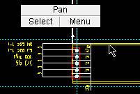
Note 3: Right-click ( Return ) in steps 4 or 5 or 7 cancels the operation.
Note 4: Undo can remove the section view from the detail, but cannot remove it from the model.
Cutting a section view on a submaterial detail :
- See cutting an erection view on a member detail . You cut a section view on a submaterial in the same way as you cut one on a member.
- Unshorten the submaterial detail before using Section View .
- You cannot cut a section view if the submaterial does not have a member associated with it. This can happen, for example, if you try to cut a section view on a material whose quantity has gone to zero. The operation will terminate, and you will get a message such as " Unable to find any member having selected material ." Zero-quantity materials can be hidden on the selection list by pressing " Hide ... " then checking the box for " Zero quantity material " on the Hide Items window.
- Any new section view that you cut can also be seen in material isolation's edit views mode in Modeling -- even if you did an Undo or did not Save , thus preventing it from being shown on the submaterial detail. If you Detail this submaterial again, the view will be incorporated into the detail.
Cutting a section view on an erection view in the Drawing Editor :
| VIDEO
|
|
A section view is cut on an erection view in the Drawing Editor . The routine not only creates the section view on the drawing, it creates a new erection view within Modeling and details that erection view.
|
|
Your current drawing must be an erection view in the Drawing Editor . This procedure creates a new erection view ( and its associated straight grid line ) in Modeling , details that erection view, and adds that erection view as a sheet item to your current erection view. Also, a section cut symbol marks where the section was cut. The width of the custom viewport that will be created on the sheet item that is added to your current erection view will be the points selected in step 2 ; the height of this viewport will be the " Up " and " Down " clipping limits set in step 4. See below for information about the actual erection view that is created using this procedure.

|
1 . Invoke Section View .
|
|
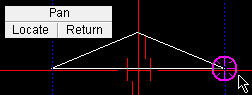
2 . Left-click ( Locate ) two points to set the width of the section cut. The arrowhead points in the " In " direction, whose distance you can set in step 3.
|
|
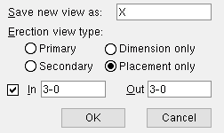
3 . The New Erection View window opens. Note that the new view name that is entered appears on the section cut symbol (in step 6 ).
|
|
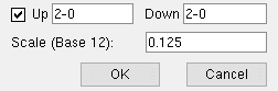
4 . This step sets the " Up " and " Down " clipping limits of the view's viewport; it also sets the view's scale .
|
|
5 . The Detail Erection Views window opens so that you can set the " Member style ," etc. of the members to be shown in the erection view.
|
|
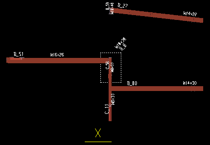
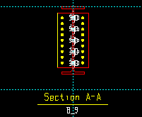
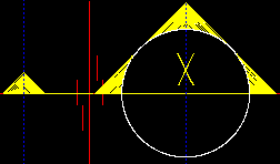
6 . A section cut symbol identifies the points you located to cut the section in step 2 . "X" in this example is the name of the new erection view.
|
|
7 . This is the custom viewport on the sheet item that was created in this example. The width of this viewport is the points located in step 2 . Its height is the Up " and " Down " clipping limits set in step 4 .
|
Note 1: If you don't like the sheet item that is created on your current view, you can delete it from your current erection view (or Undo ). Be aware, however, that you need to File > Delete View... in Modeling to remove the actual erection view and its detail that the sheet item was created from. Delete View will not let you Delete a view that is on another drawing or sheet.
Note 2: If you don't want the lettering ("X" in this example) that is on the section cut symbol , you can edit the symbol (right-click and choose " Edit " or etc.). You can Explode the symbol if you want to adjust how it is drawn.
-------------------------------
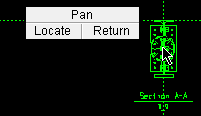
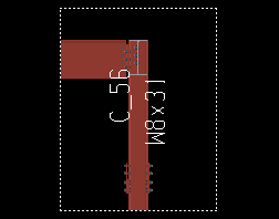
Actual Erection View (X) Created Above
|
|
The viewport shown in this example was added using Viewport Add to indicate the location of the custom viewport shown in step 7 of the above procedure. They are not the same viewports.
|
- After the above procedure, you can open the new erection view that you created.
- The actual view ("X" in the example) created by the above procedure includes all members (in their entirety) with at least one end inside the section cut points located in step 2 . For example, if one end of a member is within the located section points and its other end is 20-0 feet beyond the section points, the view actually created will extend 20-0 feet beyond the section points -- as a result, the entire member is included in the view.
- In the vertical direction, the new view created by the above procedure includes members within the depth check limits of the original view that the new view ("X") was cut from. Since " Depth checking " was off (not checked) in the created-from view, the new view ("X") includes beams at all levels of the building.
- The new view that was created ("X") does have " Depth checking " limits set since the user set " In " and " Out " to ' 3-0 ' in step 3 .
- While the new erection view ("X" in this example) is open , look in the Drawing Data Panel. " On sheet " reports the name of the erection view to which you added the new erection view as a sheet item.
- File > Delete View... in Modeling removes the view in Modeling and its Drawing Editor detail only if that view has not been placed as a sheet item.