 Beam Bearing Plate (Modeling) (new)
Tool summary:
This window opens when you add the component and can be re-opened to edit the component.
A [Beam Bearing Plate] section containing the same options that are shown here can be found on the edit window of the beam that you selected before adding the component. The bill of material and detail of that beam will also show the bearing plate.
Also see:
- Modeling (where custom components can be added)
- Custom components (topic)
- Setup Beam Bearing Plate ( Home > Project Settings > Job > Component Plugin Defaults > )
- Explode Component (makes the component no longer a component)
- Component Selection Tool (to search for custom components of a selected type)
- Model Tree (to find custom components and select them for deletion, editing, etc.)
To add, edit, or delete a Beam Bearing Plate custom component:
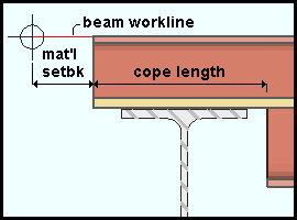
Before you begin, select the supported beam(s) that you want to add the beam bearing plate component to. Edit the beam(s) to remove any system-applied connection and top flange cope operations by ensuring that these two settings are made on the Beam Edit window:
- "Input connection type" = 'Plain end'
- "Top flange operation" = 'None' (To make this entry, you need to lock (
 ) this field.)
To add a Beam Bearing Plate custom component.
To edit a Beam Bearing Plate custom component,you can double-click its bearing plate or one of its bolts (to open the Beam Bearing Plate Edit window) or you can open its beam's edit window and change the settings that are stored in the [Beam Bearing Plate] section of that window. The Component Selection Tool can also be used to edit (and find) custom components. The "Selection filter" must be 'Default' or 'All' or 'Custom Components'' in order for you to use the double-click method of editing.
To select a Beam Bearing Plate custom component,simply click on one of its bolts or on its fill plate when the "Selection filter" is set to 'Default' or 'All' or 'Custom Components'', This selects the entire component. You can also select the appropriate member's Beam Bearing Plate listing in the model tree.
To delete a Beam Bearing Plate custom component, 1) Select the component. 2) Press the Delete key (or choose Edit > Delete).
Another way to delete a Beam Bearing Plate custom component: 1) On the component's Beam Edit window, select "Beam Bearing Plate" in the navigation tree (left panel). 2) Right-click and choose "Delete" on the menu. The [Beam Bearing Plate] section disappears. 3) Press the beam window's "OK" button to make the deletion of the component permanent.
In the Model tree, the custom component is listed under its member as Beam Bearing Plate when "View By" is set to 'Member piecemark' or 'Member number'. The component is listed after its member's connection components (Left End and Right End), and before that member's submaterials, welds and bolts
Beam Bearing Plate settings:
------ Graphical ------
Graphical: ![]() or
or ![]() .
.
- An Beam Bearing Plate component is automatically set
to "
 Graphical" whenever
you make graphical changes to any of its materials. For example, when you Edit Material or perform a material cutting operation on an Material type material. This stops the component from being changed during Process and Create Solids. Click here for more information.
Graphical" whenever
you make graphical changes to any of its materials. For example, when you Edit Material or perform a material cutting operation on an Material type material. This stops the component from being changed during Process and Create Solids. Click here for more information. - Instead of allowing the Beam Bearing Plate to be made " Graphical," you may wish to Explode Component.
------ Beam Settings ------
Beam Ends: Left End or Right End.
'Left' generates the stiffeners on the column at the left end of the beam that was selected when the Beam Bearing Plate custom component was added.
'Right' generates the stiffeners on the column at the right end of the beam that was selected when the Beam Bearing Plate custom component was added.
Tip: If you want to add beam bearing plates to both ends of a supported beam, add the beam bearing component twice -- once on each beam end.
Supporting Member Number: A member number. This list box lists the member number of any supporting beam that crosses beneath the supported beam that was selected to add this component.
'a member number' designates that Beam Bearing Plate connect to the one beam that has been assigned that selected member number. No two members in the model are ever assigned the same member number.
'0' is the only choice on this list box if the beam that was selected when the Beam Bearing Plate component was added does not have a supporting beam that crosses immediately below it. In this case, no cope is made and no bearing plate is added. '0' is applied automatically if you have deleted a supporting beam that was originally connected by this component.
Material Setback: A positive or negative (-) distance (in the primary dimension "Units" or other units) measured parallel with the workline of the beam from the beam's work point to the end of the beam. To make an entry, you need to lock (![]() ) this field. A positive distance shortens the beam by that amount. A negative (-) distance makes the beam longer. If the beam is sloping, the actual sloped minus dimension must be calculated and entered.
) this field. A positive distance shortens the beam by that amount. A negative (-) distance makes the beam longer. If the beam is sloping, the actual sloped minus dimension must be calculated and entered.
If this box is checked (
If the box is not checked (
), no cope is applied to the bottom flange.
Bearing depth: The vertical distance (in the primary dimension "Units" or other units) between the top of the supported beam and the top of the bearing plate. To make an entry, you need to lock (![]() ) this field.
) this field.
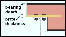
 ), changing the "Plate thickness" changes the bearing depth so that the distance from the top of the supported beam to the top of the supporting beam equals the "Bearing depth" plus the "Plate thickness."
 Cope clearance: The horizontal distance (in the primary dimension "Units" or other units) between the flange of the supporting beam and the cope on the supported beam. This applies when "Cope beam" is checked (![]() ); otherwise, it is disabled (grayed out). To make an entry, you need to lock (
); otherwise, it is disabled (grayed out). To make an entry, you need to lock (![]() ) this field. An entry made here changes the bottom 'Cope length' on the supported beam's edit window.
) this field. An entry made here changes the bottom 'Cope length' on the supported beam's edit window.
Note: If a sufficiently large "Cope length" is entered -- that is, one that would create a greater clearance than the one entered -- the "Cope length" takes precedence.
Cope length: The horizontal distance (in the primary dimension "Units" or other units) between the end of the beam and the cope, minus the "Material setback." This applies when "Cope beam" is checked (![]() ); otherwise, it is disabled (grayed out). To make an entry, you need to lock (
); otherwise, it is disabled (grayed out). To make an entry, you need to lock (![]() ) this field. An entry made here changes the bottom 'Cope length' on the supported beam's edit window.
) this field. An entry made here changes the bottom 'Cope length' on the supported beam's edit window.
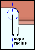
Cope radius: A distance Thedistance (in the primary dimension "Units" or other units) from the center of the cope to any point on the coped corner's circular edge. This applies when "Cope beam" is checked (![]() ); otherwise, it is disabled (grayed out). An entry made here changes the bottom 'Cope radius' on the supported beam's edit window.
); otherwise, it is disabled (grayed out). An entry made here changes the bottom 'Cope radius' on the supported beam's edit window.
------ Plate Settings ------
Surface finish: None or Sandblasted or Red oxide or Yellow zinc or Gray oxide or Blued steel or Galvanized. The "Surface finish" of the rectangular plate that the bearing plate is made of.
Note: This option is available only when you add the component. If you want to change it later, change the "Surface finish" on the Rectangular Plate Window.
| sand blasted | red oxide | yellow zinc |
| gray oxide | blued steel | galvanized |
Steel grade: A36 or A572-42 or A572-42 or A572-52 or etc. The "Steel grade" of the rectangular plate material that the bearing plate is made of.
Setup: If the grade of steel you want is not shown on the list box (
), you can use Home > Project Settings > Job > Plate Grades to add it to the list.
Plate thickness: The thickness (in the primary dimension "Units" or other units) of the bearing plate. This also sets the "Material thickness" of the rectangular plate material that the bearing plate is made of.
Note: When "Bearing depth" is unlocked (
Plate width: The width (in the primary dimension "Units" or other units) of the bearing plate. This also sets the "Material width" of the rectangular plate material that the bearing plate is made of. To make an entry, you need to lock (![]() ) this field.
) this field.
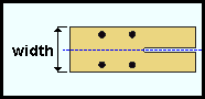
Plate length: The length (in the primary dimension "Units" or other units) of the bearing plate. This also sets the "Order length" of the rectangular plate material that the bearing plate is made of. To make an entry, you need to lock (![]() ) this field. Changing the plate's length also changes the "Plate overlap;" consequently, you can lock the "Plate overlap" or the "Plate length" fields, but not both.
) this field. Changing the plate's length also changes the "Plate overlap;" consequently, you can lock the "Plate overlap" or the "Plate length" fields, but not both.
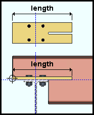
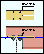
Plate overlap: The distance (in the primary dimension "Units" or other units) by which the bearing plate overlaps the cope. To make an entry, you need to lock (![]() ) this field. Changing the plate's overlap also changes the "Plate overlap;" consequently, you can lock the "Plate overlap" or the "Plate length" fields, but not both.
) this field. Changing the plate's overlap also changes the "Plate overlap;" consequently, you can lock the "Plate overlap" or the "Plate length" fields, but not both.
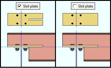
If this box is checked (
If the box is not checked (
------ Hole/Bolt Settings ------
If this box is checked (
If the box is not checked (
Align bolts along beam gages: ![]() or
or ![]() .
.
If this box is checked (
), holes and field bolts are added along one or more gages matching the flange gages of the supported beam that is specified in the local shape file. If you enter a distance into the "Supported..." or "Supporting beam gage" field, any difference in spacing will be equally distributed between the near side and far side gages.
If the box is not checked (
), holes and field bolts are added along gages whose spacing and positions you specify
Hole to plate edge: A distance (in the primary dimension "Units" or other units) from hole furthest from the beam to the plate edge. Applies when "Align bolts along beam gages" is not checked ().
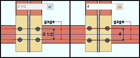
Supported beam gage: The specifies the distance (in the primary dimension "Units" or other units) between flange gages on the supported beam. To make an entry, you need to lock (![]() ) this field. If this field is unlocked (
) this field. If this field is unlocked (![]() ), this is a read-only distance matching the beam's flange gages in the local shape file.
), this is a read-only distance matching the beam's flange gages in the local shape file.
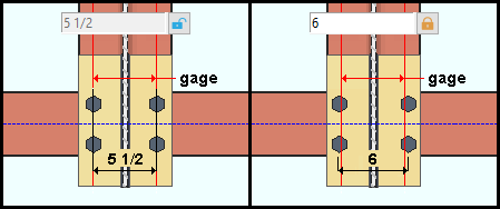
Supporting beam gage:The specifies the distance (in the primary dimension "Units" or other units) between flange gages on the supporting beam. To make an entry, you need to lock (![]() ) this field. If this field is unlocked (
) this field. If this field is unlocked (![]() ), this is a read-only distance matching the beam's flange gages in the local shape file.
), this is a read-only distance matching the beam's flange gages in the local shape file.
Note: If this field is locked (
) and"Align bolts..." is unchecked (
Rows of bolts: 1 or 2 Applies when "Align bolts along beam gages" is not checked ().
'1' provides a single row of two field bolts, one on each side of the web of the supported beam.
'2' provides two rows of field bolts. This setting is not available when the supported beam does not extend beyond the center line of the supporting beam, or when there is no supporting member
Gage side to bolt: NS or FS or Both or None. Specifies which "Supporting beam gage " gets holes and field bolts, if any.
When "Supporting beam gage" is unlocked (![]() ), the bolts are placed along a flange gage of the supporting beam that is specified in the local shape file. Applies when "Align bolts along beam gages" is checked (
), the bolts are placed along a flange gage of the supporting beam that is specified in the local shape file. Applies when "Align bolts along beam gages" is checked (![]() )
)
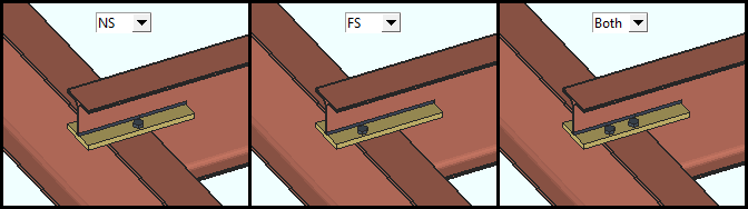
'NS' Field bolts the supported beam to the near side of the flange of the supporting beam. "Near side" refers here to the side of the flange nearest to the supported beam. When the supported beam does not extend beyond the center line of the supporting beam, this is the only setting available.
'FS' Field bolts the supported beam to the far side of the flange of the supporting beam. "Far side" refers here to the side of the flange furthest from the supported beam. This setting only applies when the supported beam extends beyond the center line of the supporting beam.
'Both' . Field bolts the supported beam to both sides of the flange of the supporting beam. This setting only applies when the supported beam extends beyond the center line of the supporting beam.
'None' The supported beam is not field bolted. This is the only setting available when there is no supporting member; that is, when the "Supporting Member Number" is '0.
Hole type: Standard Round or Oversized Round or Cope Hole or Erection Pin Hole or Anchor Bolt Hole or Plug Weld Hole or Grout Hole or Vent/Drain or Short Slot or Long Slot or User slot #1 or User slot #2 . This is the type of hole on the beam bearing plate.

A 'Standard Round' hole is perfectly round and has a "Hole diameter" that is typically 1/16 inch larger than the "Bolt diameter." See Table J3.3 or Table J3.3M (AISC Thirteenth Edition, p. 16.1-105).
An 'Oversized Round' hole will typically input a "Hole diameter" 3/16 inch larger than the "Bolt diameter."
A 'Cope Hole' is for using a punch or drilling machine instead of a cutting machine to cope a piece of material. No bolt will be added to this type of hole.
An 'Erection Pin Hole' is a hole on the end of a column for use by a crane to lift the column into place. No bolt will be added to this type of hole.
An 'Anchor Bolt Hole' is a hole for anchor bolts in a column base plate. No bolt will be added to this type of hole.
A 'Plug Weld Hole' is for adding to a material before the material is plug welded. No bolt will be added to this type of hole.
A 'Grout Hole' hole may be used for pouring grout under a base plate. No bolt will be added to this type of hole.
A 'Short Slot' hole is oblong in shape and has a relatively short "Slot length" (1 5/16 inch for a 1 inch diameter bolt).
A 'Long Slot' hole is oblong in shape, has a diameter 1/16 inch larger than the input bolt diameter, and has a relatively long "Slot length" (2 1/2 inch for a 1 inch diameter bolt).
A 'Vent Drain' hole is a vent hole or drain hole for galvanizing. No bolt will be added to this type of hole.
'User Slot #1' and 'User Slot #2' are slots whose "Slot length" are set, based on the "Bolt diameter," from user-entered length settings maintained at Home > Project Settings > Job > User Slot Lengths.
Hole diameter: A calculated or user-entered distance. On a 'Standard round' hole, the program-calculated value will be larger than the input bolt diameter.
To make an entry, you need to lock (![]() ) this field.
) this field.
Slot length:
A calculated or user-entered ' slot-length. This applies when the "Hole type" is 'Long slot' or 'Short slot' or User Slot #1' or 'User Slot #2'. To make an entry, you need to lock (![]() ) this field. If this field is unlocked (
) this field. If this field is unlocked (![]() )...
)...
- For a 'Long slot' or a 'Short slot', the program-calculated length is the standard slot length based on the "Bolt diameter" and "Hole type" per the connection design method. For an AISC design code, the calculation is done per Table J3.3 or Table J3.3M (AISC Thirteenth Edition, p. 16.1-105).
- For a 'User slot #1' or 'User slot #2', the calculated slot length comes from Home > Project Settings > Job > User Slot Lengths.
| slot length |
|
|
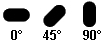
Slot rotation: A positive or negative number from 90 to -90 degrees. This applies when the "Hole type" is 'Long slot' or 'Short slot' or User Slot #1' or 'User Slot #2'. Slot rotations can be modeled to a precision of 0.1 degree.
Bolt type: A325N or A325SC or A325X or etc. Select a bolt type from the list box (![]() ). The bolts that are listed come from Home > Project Settings > Job > Bolts, Washers, and Holes > Bolt Specifications.
). The bolts that are listed come from Home > Project Settings > Job > Bolts, Washers, and Holes > Bolt Specifications.
Bolt diameter: A diameter. Choose a bolt diameter from the list box (![]() ). The diameters that are listed in the list box come from the "Available bolts" list at Home > Project Settings > Job > Bolt Settings.
). The diameters that are listed in the list box come from the "Available bolts" list at Home > Project Settings > Job > Bolt Settings.
| diameter |
|
------ Weld Settings ------
If this box is checked (
If the box is not checked (
Weld type: A Fillet This applies when "Add weld" is set to 'Yes'. It sets the weld "Type" on the Weld Edit window in Modeling as well as the weld "Type" for the weld symbol on the beam detail.
| name | name | weld used for... |
|
|
fillet | General welding of material. |
Weld size: A distance (in the primary dimension "Units" or other units) that indicates depth of preparation, size or strength of the weld. This sets the "Weld size" on the Weld Edit window in Modeling as well as the "Weld size" for the weld symbol on the beam detail.

