Caged Ladder Member
 Misc Steel > "Caged Ladder"
Add (or review) a ladder member with or without a cage. The ladder can optionally be connected to a beam member.
- General Overview
- Step-By-Step
- Tips and Tricks
Caged ladder (general settings)
Sequence: Any sequence name from the Sequence Names list can be entered here.
Defaults: The sequence assigned by default to the first Caged Ladder member that is added after you first start up Modeling is the sequence listed in line 1 of the Sequence Names list. The default sequence for each subsequently added Caged Ladder member during the same session in Modeling becomes the sequence assigned to the last-added or last-edited Caged Ladder member.
To assign a different sequence, you can type in any sequence name that is on the Sequence Names list, or you can click the list box
( and select any sequence name that is on the list.)
Model complete date: **NOT SET** or a month day year.
Surface Finish : None or Sandblasted or Red oxide or Yellow zinc or Gray oxide or Blued steel or Galvanized or Duplex Coating or Undefined 1 or Undefined 2 or Undefined 3 or Red oxide 2 or Any user added surface finish. This affects the colors of 'Solid' members on erection views in the Drawing Editor. This also sets the color when "Output material color" is set to 'Surface finish' for a VRML Export or a DWG/DXF Export. The "Color" (not "Surface finish") sets the color of this material in Modeling.
| sand blasted | red oxide | yellow zinc | user surface finish 1 |
| gray oxide | blued steel | galvanized | user surface finish 2 |
To assign a different surface finish, you can drop-down the current surface finish and select the one you want, or you can press the "file cabinet" browse button
( and double-click any surface finish that is on the list.)
Graphical: ![]() or
or  .
.
If the box is checked
( , then changes made on the custom member's edit window will not be applied, thus preserving all graphical changes that were made to the custom member's or component's materials, bolts or welds. This means that when you press "OK" on the edit window, or when you Process a custom member or a custom component, no new materials will be generated.If the box is not checked
( , it indicates the member has not had a modification made to it outside of the member edit window. If the box is being unchecked from a checked state, and the custom member was formerly made graphical due to at least one of its materials, bolts or welds being altered or deleted, then after "OK" is pressed all of the member's materials, bolts, and welds will be deleted. New materials, bolts, and welds will be generated per the settings on the window. Any graphical changes that you made to materials, bolts, and welds will be lost.)
Warning: Any graphical changes that you make to materials will be preserved only so long as the custom member is set to
" . For this reason, you should make changes on a custom member's edit window before you begin to graphically alter the custom-member material. Otherwise, any graphical changes that you make will be lost.
Add BOTTOM VIEW: ![]() or . The default state is unchecked )
or . The default state is unchecked )
When checked
( , a BOTTOM view is added to the detailing View list of the Caged Ladder member. This is the same as using Member Isolation and adding a Preset BOTTOM view.When unchecked
( from a previously checked( state, the BOTTOM view is removed from the detailing View list of the Caged Ladder member.
![]() Copy, Paste, Save, Load buttons:
Copy, Paste, Save, Load buttons:
- The position of these "form" buttons on the window tells you what settings they apply to. Click here for more information.
- You can
 Copy the settings on this window, then
  Paste those settings to a different edit window of the same type.
- You can
 Save the settings on this window to a file stored in a global folder that is used by your current version of SDS2. Give the file a name that will help other users identify its purpose. You can
  Load a saved file to replace the settings on this window (except Piecemark) with the settings that are stored in the file you select.
- When editing multiple windows at the same time, Paste and Load replace mixed entries to a single field with a single entry. Copy and Save ignore fields with mixed entries, treating them as if they have no entry or do not exist.
Properties opens the Edit Properties window, on which you can make entries to custom properties. If your current Job was set to use a legacy flavor when it was created, the window that opens is named Custom Properties , not Edit Properties.
Tip: The Edit Properties window can also be used to read
Log entries or review or type
Tip: The Member Properties command is an alternative to this button. It opens the Edit Properties window directly, without your first having to open a member edit window.
Status opens the Member Status Review window, which can give you additional information about the member, and which you can use to enter status information or designate a member as an existing member.
Note: This button shows
if one or more Repeat check boxes on the Member Status Review window do not match the checked-unchecked state of same-named fields in User and Site Options > Site > Member status items to copy/repeat. On the Status Review window, the fields that do not match User and Site Options are plotted in red .
OK (or the Enter key) closes the edit window and saves any changes you have made on the window to the member file.
Solids on OK: If the appropriate choice is made to User and Site Options > Modeling > Automatically process after modeling operation, then this member will automatically be regenerated (Create Solids will take place) after your press OK. Otherwise, you will have to manually Process and Create Solids in order for changes you made on this window to be fully updated in the 3D model.
Change all: If you Edit Member (one member only) and make a change that potentially triggers the Do you want to change all ... dialog and the 3D model contains more than one member of the same type that has the same piecemark as the member you changed, a yes-no dialog opens. On it is the question, Do you want to change all (members with this piecemark). Press the Yes button to change all the members; press the No button to change only this member.
Cancel (or the Esc key or the ![]() button) closes the edit window without saving any changes that you have made. Cancel does not undo a Detail Member operation.
button) closes the edit window without saving any changes that you have made. Cancel does not undo a Detail Member operation.
Note: If you opened this window while adding a member, Cancel brings you back to the work point location step of adding a member.
Tip: Any time you use Edit Member just to review a member (and you do not want to set the defaults for to-be-added members), the best way to close this window is to Cancel.
Reset undoes any changes made since you opened this window.
Exception: Reset does not undo changes made using the Add View, Delete View, Detail Member, and View detail buttons.
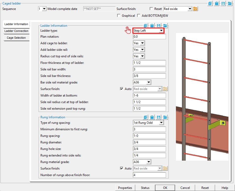
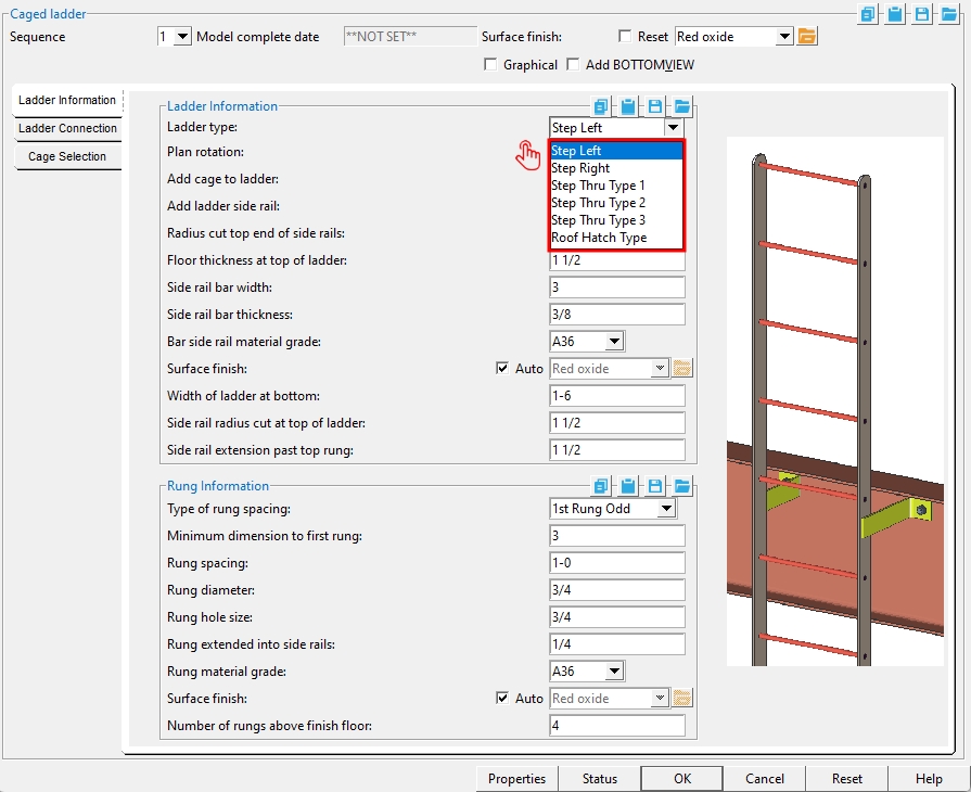
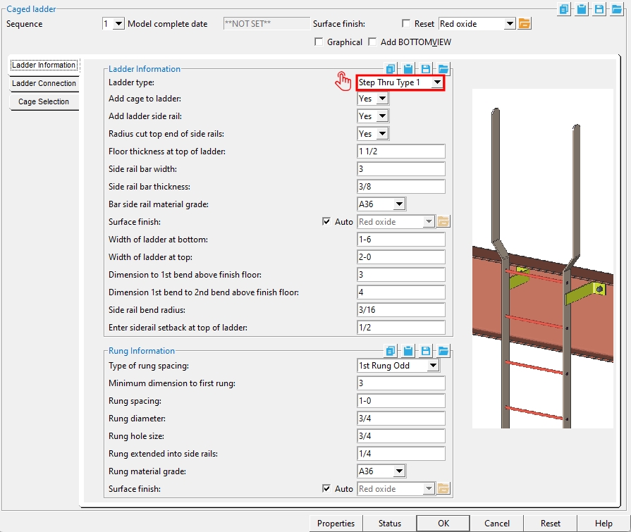
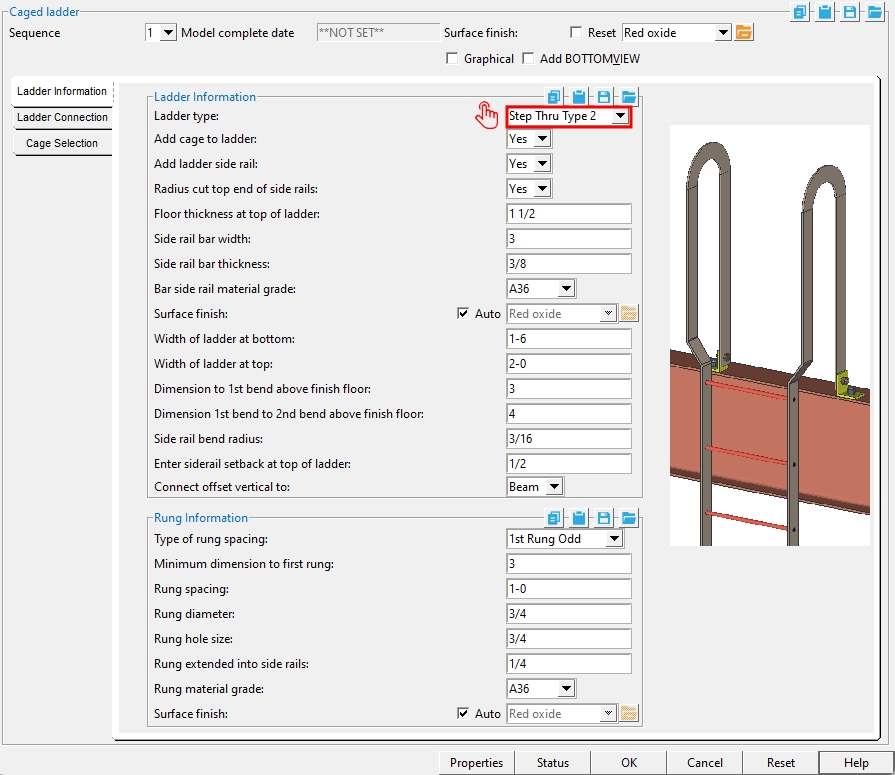
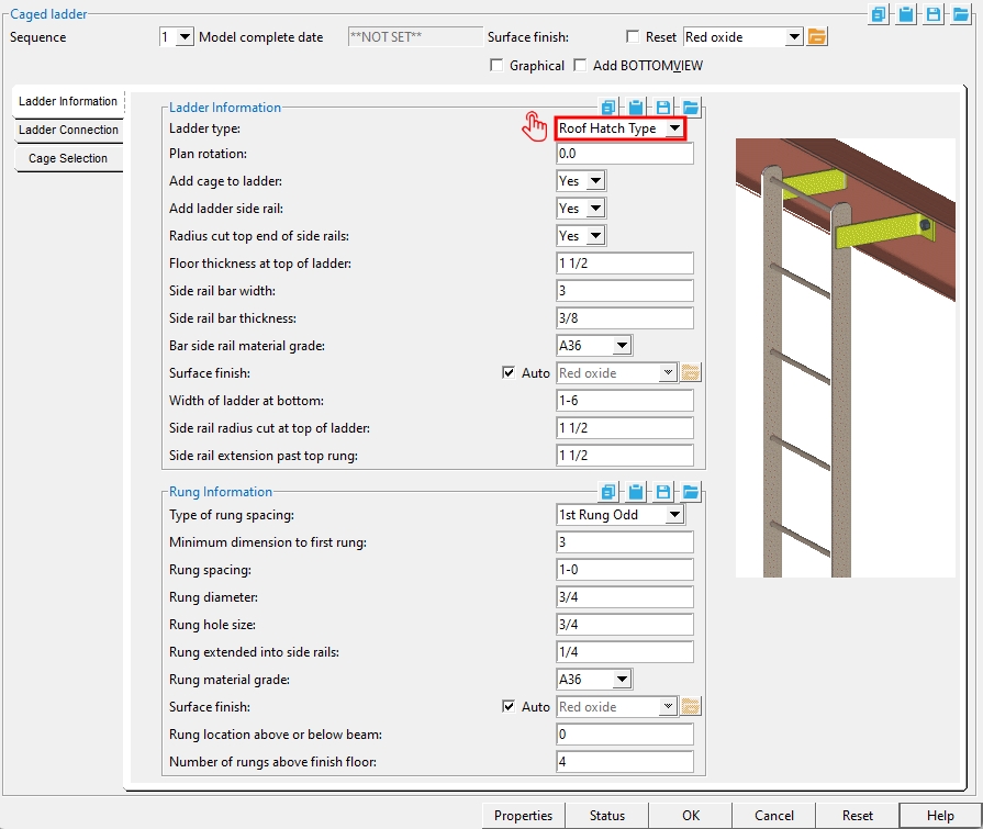
Ladder Information > Ladder Information
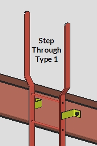
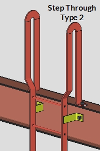
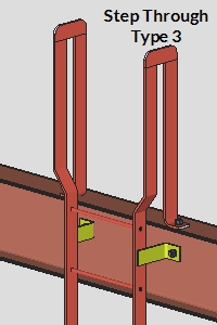
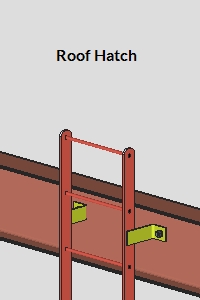
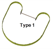
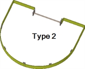
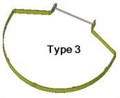
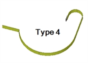
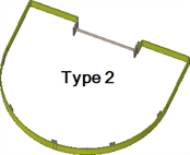
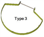
Ladder type: Step Left or Step Right or Step Thru Type 1 or Step Thru Type 2 or Step Thru Type 3 or Roof Hatch Type. You need to have added the ladder to a beam in order to select 'Step Thru Type 1' 'Step Thru Type 2' or 'Step Thru Type 3'.
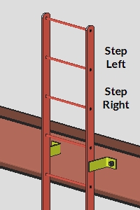
|
|
|
|
|
Plan rotation: A number of degrees. This applies when you have added a ladder without selecting a beam.
Add cage to ladder: Yes or No.
'Yes' enables settings under the "Cage Selection" tab.
'No' disables (grays out) the "Cage Selection" tab.
Add ladder side rail: Yes or No.
|
Note: To edit a caged ladder, you can double-click one of its side rails. If your caged ladder does not have side rails, you can still edit it using the Model Tree or Edit Member.
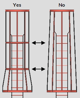
Radius cut top end of side rails: Yes or No.
|
'Yes' cuts the corners at the top of the side rails based on the "Side rail radius cut at top of ladder".
'No' keeps the top corners of the side rails square.
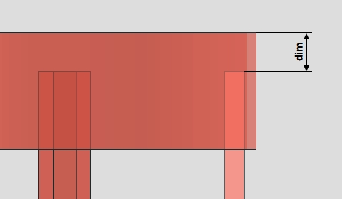
Floor thickness at top of ladder: The distance from the beam's top flange to the finished floor surface.
Side rail bar width: The distance that is the "Material width" of the bent plate layout material that makes the side rails.
|
Side rail bar thickness: The distance that is the "Material thickness" of the ladder's bent plate layout material that makes the side rails.
|
Bar side rail material grade: A36 or A572 or etc. This is "Steel grade" of the bent plate layout material that makes the side rails. If the steel grade you want is not on the list box ![]() )
)
Surface Finish :None or Sandblasted or Red oxide or Yellow zinc or Gray oxide or Blued steel or Galvanized or Duplex Coating or Undefined 1 or Undefined 2 or Undefined 3 or Red oxide 2 or Any user added surface finish. This affects the colors of 'Solid' members on erection views in the Drawing Editor. This also sets the color when "Output material color" is set to 'Surface finish' for a VRML Export or a DWG/DXF Export. The "Color" (not"Surface finish") sets the color of this material in Modeling.
| sand blasted | red oxide | yellow zinc | user surface finish 1 |
| gray oxide | blued steel | galvanized | user surface finish 2 |
To assign a different surface finish, you can drop-down the current surface finish and select the one you want, or you can press the "file cabinet" browse button
( and double-click any surface finish that is on the list.
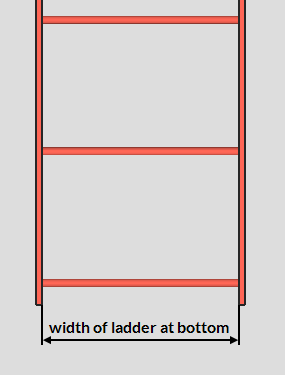
Width of ladder at bottom: The distance between the interior faces of the side rails at the bottom of the ladder.
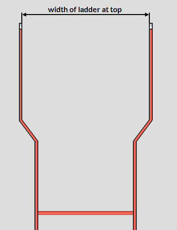
Width of ladder at top: The distance between the interior faces of the side rails at the top of the ladder for a 'Step Thru Type 1' or 'Step Thru Type 2' or 'Step Thru Type 3' ladder.
Side rail radius cut at top of ladder: The cut radius that is applied to the top corners of the side rails. This applies when "Radius cut top end of side rails" is set to 'Yes'.
A cut radius of 0 keeps the top corners of the side rails square (no cuts).
A small cut radius, such as one between 1/6 and 1/3 the width of the side rails, rounds the corners of the side rails while keeping the tops of the side rails flat.
A cut radius of half the side-rail width rounds the tops of the side rails. Larger radii do the same.
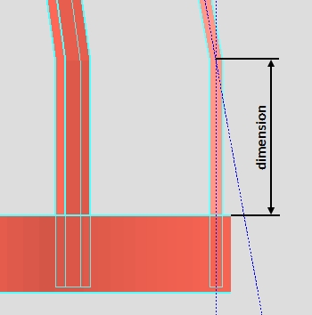
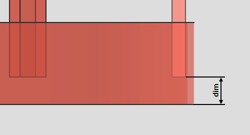
Side rail extension past top rung: The distance from the top of the top rung to the top of the ladder.
|
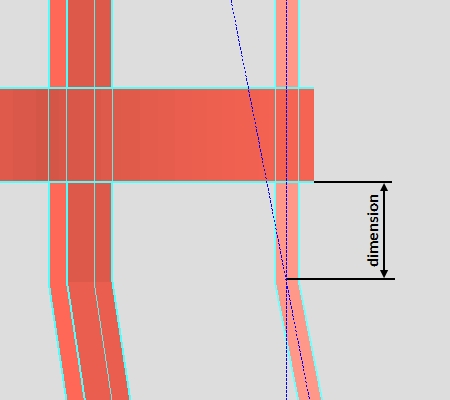
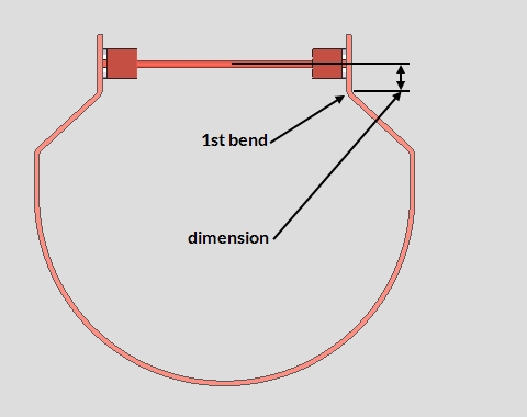
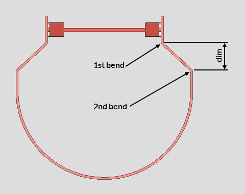
Dimension to 1st bend above finish floor: The distance from the top of the finished floor to the first bend of a 'Step Thru Type 1' or 'Step Thru Type 2' or 'Step Thru Type 3' ladder.
Dimension 1st bend to 2nd bend above finish floor: The distance from the top of the first bend to the second bend on a 'Step Thru Type 1' or 'Step Thru Type 2' or 'Step Thru Type 3' ladder.
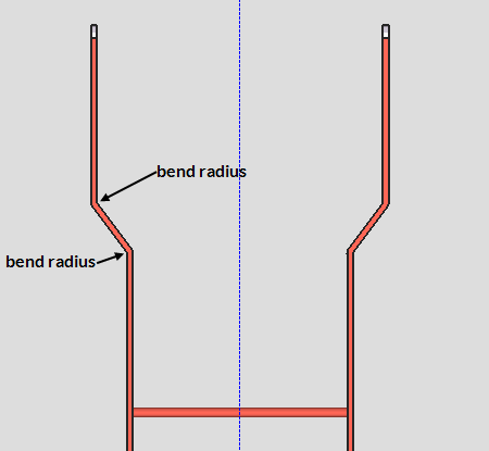
Side rail bend radius: A number of degrees. This applies to 'Step Thru Type 1' and 'Step Thru Type 2' and 'Step Thru Type 3'.
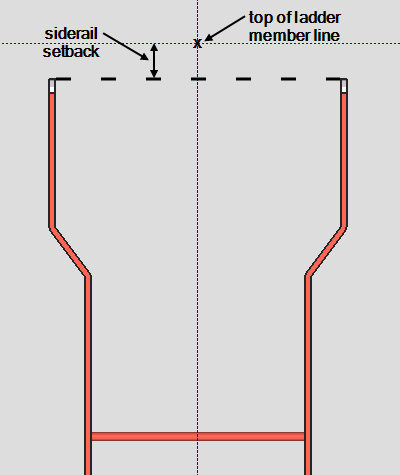
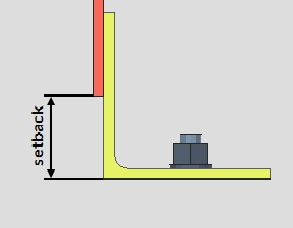
Enter siderail setback at top of ladder: The distance from the top of the ladder's member line to the top of the siderails. This applies to 'Step Thru Type 1' and 'Step Thru Type 2' and 'Step Thru Type 3'.
Connect offset vertical to: Beam or Floor. This applies to 'Step Thru Type 2' and 'Step Thru Type 3'.
| Beam |
|
Floor |
'Beam' results in the "Top Offset Connection" being bolted (or welded) to the beam.
'Floor' results in the connection being moved to the "Floor thickness at top of ladder" above the beam. In the example above, there is no longer any surface to bolt the clip angle to, and therefore no bolt is generated.
Ladder Information > Rung Information
Type of rung spacing: First Rung Odd or All Rungs Equal.
'First Rung Odd' uses the "Minimum dimension to first rung" to determine the first rung's position.
'All Rungs Equal' distributes the rungs evenly using the "Rung spacing". The first rung is placed the "Rung spacing" distance from the bottom of the ladder. The bottom of the ladder is at the bottom of the ladder's work line.
Minimum dimension to first rung: The distance from the bottom work point to the top of the bottom rung. This applies when the "Type of rung spacing" is set to 'First Rung Odd'.
Rung spacing: The distance from the top of one rung to the next.
|
Rung diameter: The diameter of the round bar material to be used for ladder rungs.
|
Rung hole size: The diameter of the holes in the side rails that the rungs are inserted into.
Rung extended into side rails: The distance that the rungs are extended into the rung holes.
Rung material grade: A36 or A572 or etc. This is "Steel grade" of the round bar rungs. If the steel grade you want is not on the list box ![]() )
)
Rung location above or below beam: Under Construction
Number of rungs above finish floor: The number of rungs that you want above the top of the finished floor. This applies when the "Ladder type" is 'Step Left' or 'Step Right' or 'Roof Hatch Type'.
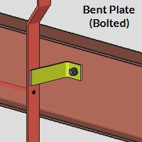
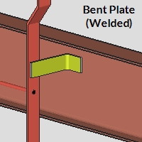
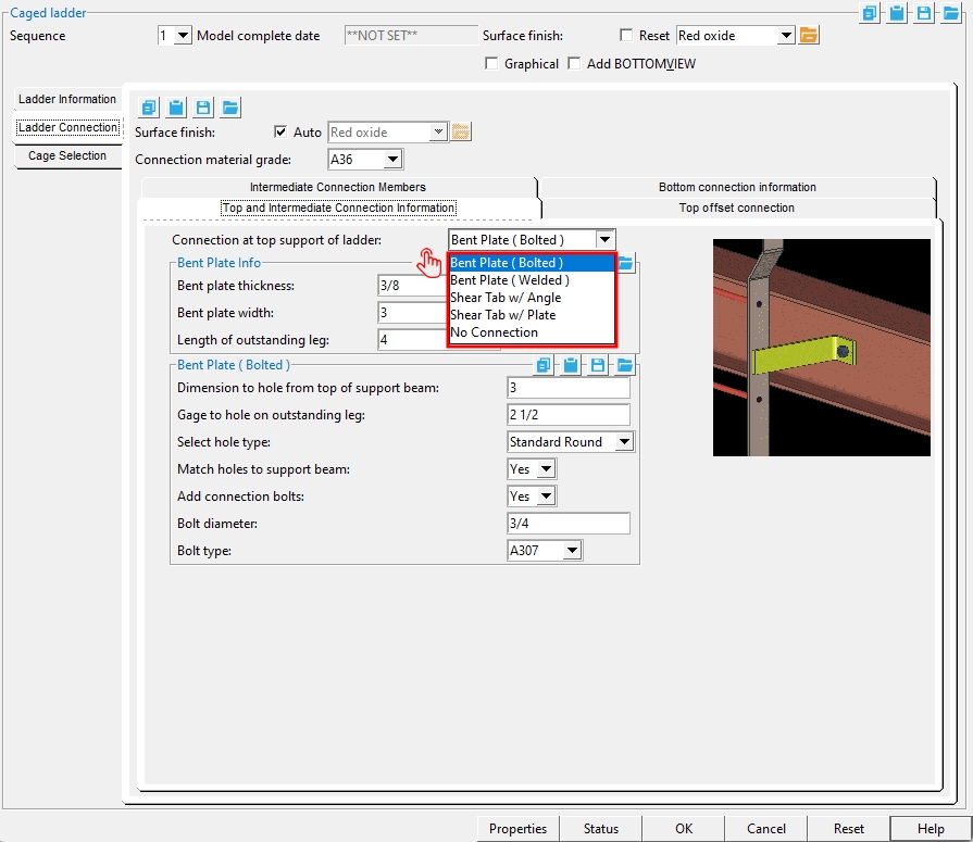
Ladder Connection > Top and Intermediate Connection Information > Bent Plate (Bolted) and Bent Plate (Welded)
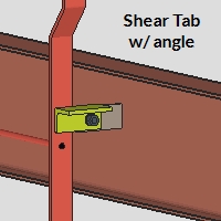
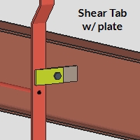
Connection at top support of ladder: Bent Plate (Bolted) or Bent Plate (Welded) or Shear Tab w/ Angle or Shear Tab w/ Plate or No Connection. This is the connection type for connecting each side rail of the ladder to the web of the support beam.
|
|
|
|
Bent plate thickness: The value here sets the "Material thickness" of the bent plate material.
Bent plate width: The value entered here sets the "Material length" of the bent plate material.
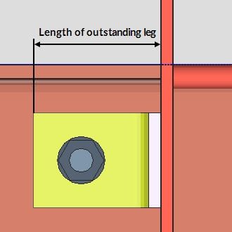
Length of outstanding leg: The distance measured from the outside face of bent plate to the toe of the outstanding leg (OSL). The value entered here sets the "Length leg 2" of the bent plate material. The OSL connects to the supporting beam member.
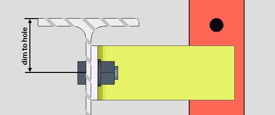
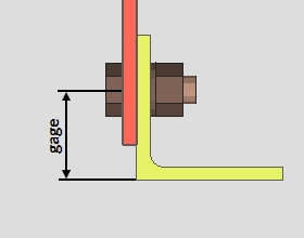
Dimension to hole from top of support beam: The distance measured from the top of supporting beam member to the center of the hole located in the bent plate's outstanding leg.
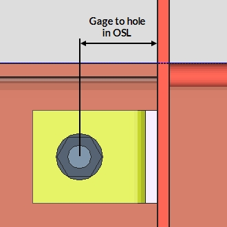
Gage to hole on outstanding leg: The distance measured from the outside face of bent plate to the to the center of the hole located in the bent plate's outstanding leg (OSL).
Match holes to support beam: Yes or No.
Yes: The hole in the bent plate's outstanding leg is matched to the supporting beam's web.
No: The hole in the bent plate's outstanding leg is not matched to the supporting beam's web.
Add connection bolts: Yes or No.
Yes: Bolts are added to the bent plate connection.
No: Bolts are not added to the bent plate connection.
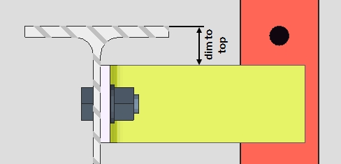
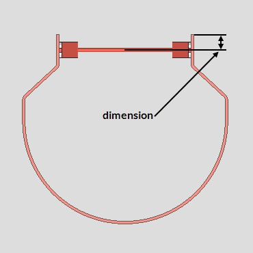
Dimension to top of plate from top of support beam (vertical): The distance measured from the top of supporting beam member to the top of the bent plate.
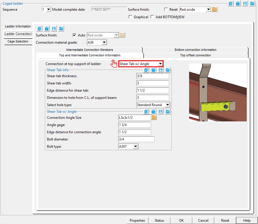
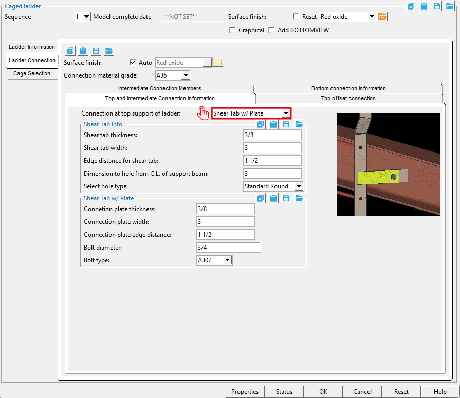
Ladder Connection > Top and Intermediate Connection Information > Shear Tab w/ Angle and Shear Tab w/ Plate
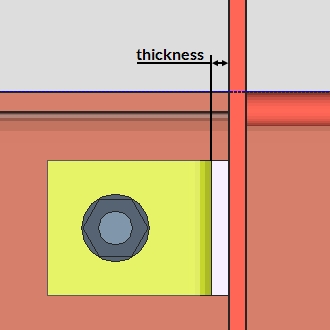
Shear tab thickness: The value entered here sets the "Material thickness" of the shear tab's rectangular plate material.
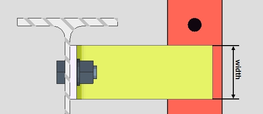
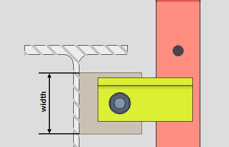
Shear tab width: The distance measured vertically from the top edge to the bottom edge of the shear tab. The value entered here sets the "Work point distance" of the shear tab's rectangular plate material.
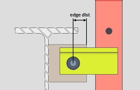
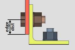
Edge distance for shear tab: The distance measured horizontally from the center of the hole to the free-edge of the shear tab.
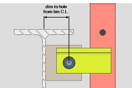
Dimension to hole from C.L. of support beam: The distance measured horizontally from the center of the supporting beam's web to the center of the hole. This applies to all connection materials.
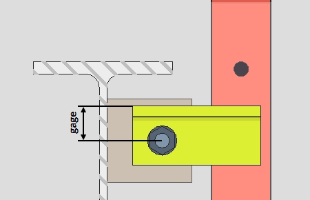
Angle gage: The distance measured from the heel of the angle to the center of the hole in the angle leg.
Edge distance for connection angle: The distance measured horizontally from the center of hole to the free-end of the angle.
Connection plate thickness: The value entered here sets the "Material thickness" of the connection plate's flat bar material.
Connection plate width: The distance measured vertically from the top edge to the bottom edge of the connection plate. The value entered here sets the "Material width" of the connection plate's flat bar material.
Connection plate edge distance: The distance measured horizontally from the center of hole to the free-end of the connection plate.
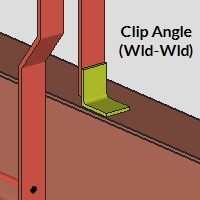
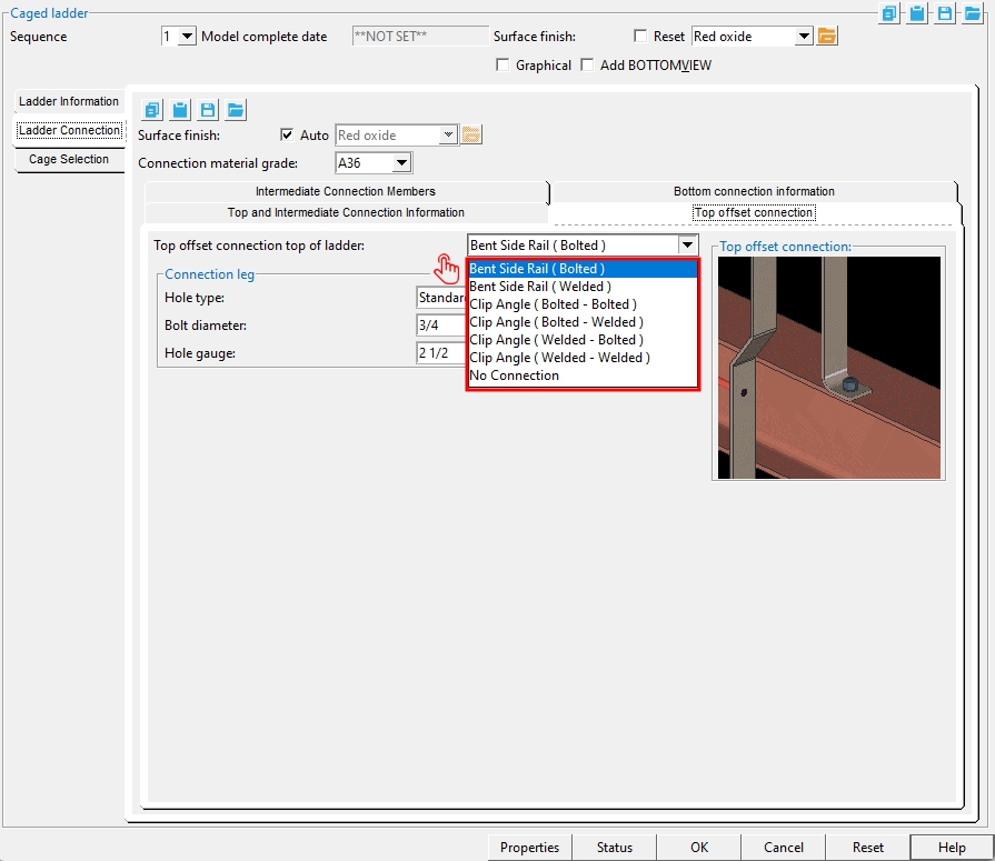
Ladder Connection > Top offset connection
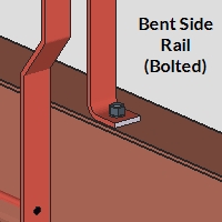
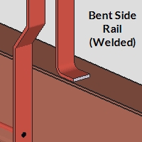
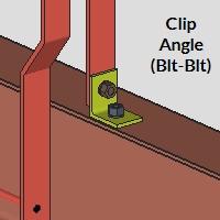
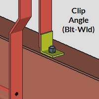
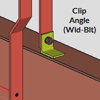
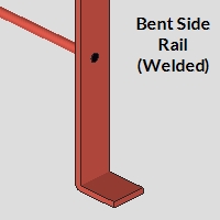
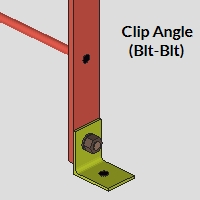
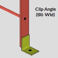
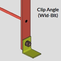
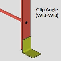
Top offset connection at top of ladder: Bent Side Rail (Bolted) or Bent Side Rail (Welded) or Clip Angle (Bolted - Bolted) or Clip Angle (Bolted - Welded) or Clip Angle (Welded - Bolted) or Clip Angle (Welded - Welded) or No Connection. This applies when the "Ladder type" is 'Step Thru Type 2' or 'Step Thru Type 3'.
|
|
|
|
|
|
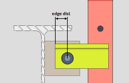
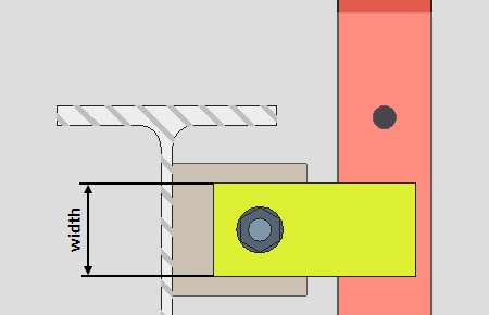
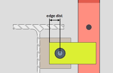
Hole gauge: Definition varies by connection type. See the examples below.
Bent Side Rail (Bolted): The distance measured horizontally from the inside face of rail to the center of the hole in the rail's bent leg.
_holegauge.jpg)
_holegauge.jpg)
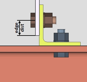
Connection to leg: The distance measured horizontally from the inside face of rail to the center of the hole in the clip angle's horizontal leg.
Leg to ladder: The distance measured vertically from the heel of the clip angle to the hole in the clip angle's vertical leg.
Clip Angle (Bolted - Welded): The distance measured horizontally from the inside face of rail to the center of the hole in the clip angle's horizontal leg.
_holegauge.jpg)
Clip Angle (Welded - Bolted): The distance measured vertically from the heel of the clip angle to the hole in the clip angle's vertical leg.
_holegauge.jpg)
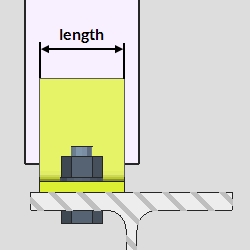
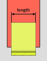
Connection angle length: The distance measured horizontally from end-to-end of the connection angle. The value entered here sets the "Work point distance" of the rolled section material.
Leg direction: Horizontal or Vertical. This is the toe direction of the long leg of the "Connection angle size".
'Horizontal' sets the clip angle's long leg horizontally as the connection leg to the supporting beam.
'Vertical' sets the clip angle's long leg vertically as the leg to the ladder's rail.
Hole edge distance: The distance measured vertically from the edge of the ladder's rail to the center of the hole. The edge of the ladder's rail material moves up or down when this value is changed.
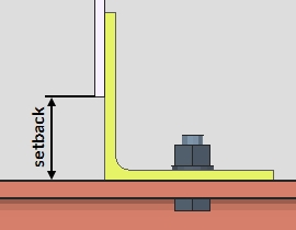
Setback dimension to end of bar: The distance measured vertically from top of supporting beam to the edge of the ladder's rail material. When the "Connection at bottom of supports of ladder" is set to 'No Connection', this is the distance from the bottom work point of the ladder to the edge of the rail material.
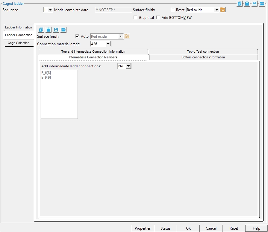
Ladder Connection > Intermediate Connection Members
Add intermediate ladder connection: Yes or No. This applies only if you selected a beam in step 2.
'Yes' lets you select beams from the list of beams that are in approximate alignment and at lower elevations than the beam that you selected when you added this caged ladder. The beam(s) you select will use the "Connection at top support of ladder" and other related settings under the "Top and Intermediate Connection Info" tab.
'No' results in connections being applied only to the beam that you selected in step 2.
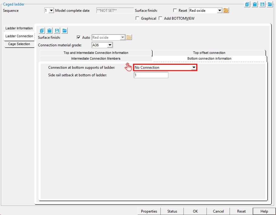
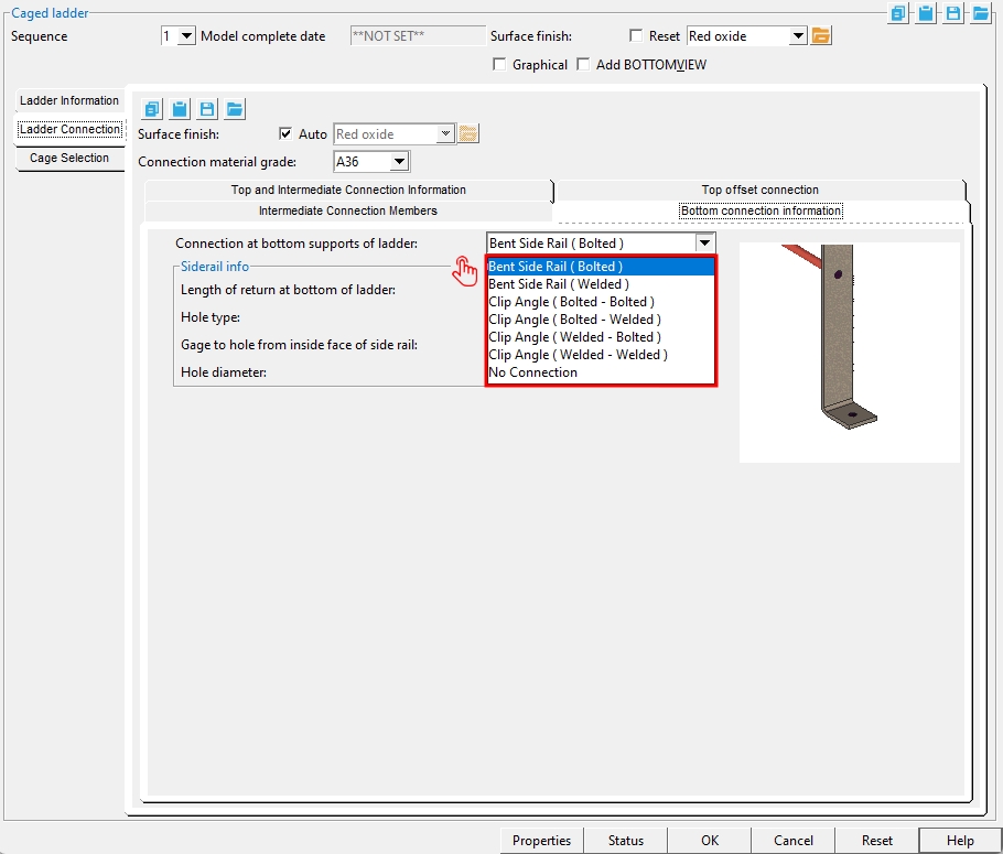
Ladder Connection > Bottom connection information
Connection at bottom supports of ladder: Bent Side Rail (Bolted) or Bent Side Rail (Welded) or Clip Angle (Bolted - Bolted) or (Clip Angle (Bolted - Welded) or Clip Angle (Welded - Bolted) or Clip Angle (Welded - Welded) or No Connection.

|
|
|
|
|
|
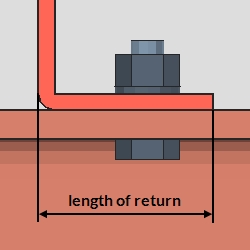
Length of return at bottom of ladder: The distance measured horizontally from the inside face of ladder rail to the toe of the bent leg at the bottom of the rail.
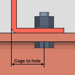
Gage to hole from inside face of side rail: The distance measured horizontally from the inside face of rail to the center of the hole in the rail's bent leg or clip angle.
Hole diameter: The value entered here sets the "Hole diameter" for the bent rail leg or clip angle connection.
Clip angle size: Type in any angle section size that is in the local shape file or press the "file cabinet" browse button )
Clip angle length: The distance measured horizontally from end-to-end of the clip angle. The value entered here sets the "Work point distance" of the rolled section material.
Long leg toe direction: Vertical or Horizontal. This is the toe direction of the long leg of the "Connection angle size".
'Horizontal' sets the clip angle's long leg horizontally as the connection leg.
'Vertical' sets the clip angle's long leg vertically as the leg to the ladder's rail.
Clip angle gage for hole to side rail (vertical): The distance measured vertically from the heel of the clip angle to the hole in the clip angle's vertical leg.
Hole type in clip angle: Standard round or Short slot or Long slot.
Side rail hole edge distance: The distance measured vertically from the edge of the ladder's rail to the center of the hole. The edge of the ladder's rail material moves up or down when this value is changed.
Side rail setback at bottom of ladder: The distance measured vertically from heel of angle to the edge of the ladder's rail material.
Surface Finish :None or Sandblasted or Red oxide or Yellow zinc or Gray oxide or Blued steel or Galvanized or Duplex Coating or Undefined 1 or Undefined 2 or Undefined 3 or Red oxide 2 or Any user added surface finish. This affects the colors of 'Solid' members on erection views in the Drawing Editor. This also sets the color when "Output material color" is set to 'Surface finish' for a VRML Export or a DWG/DXF Export. The "Color" (not"Surface finish") sets the color of this material in Modeling.
| sand blasted | red oxide | yellow zinc | user surface finish 1 |
| gray oxide | blued steel | galvanized | user surface finish 2 |
To assign a different surface finish, you can drop-down the current surface finish and select the one you want, or you can press the "file cabinet" browse button
( and double-click any surface finish that is on the list.
Connection material grade: A36 or etc. This sets the "Steel grade" for the rectangular plate, bent plate, channel, angle, or flat bar material that is used as connection material.
Select hole type: Standard Round or Oversized Round or Short Slot or Long Slot.
Hole type: Standard Round or Short Slot or Long Slot.
Slot length: The length of a Short Slot or Long Slot. This setting is hidden until Select hole type or Hole type are set to Short Slot or Long Slot.
Bolt diameter: The diameter of the shank of the bolt.
![]()
Bolt type: A307 or A325N or A325SC, etc. The bolt types shown in this list box ![]() )
)
Connection angle size: Type in any angle section size that is in the local shape file. Where available, you can also press the "file cabinet" browse button )
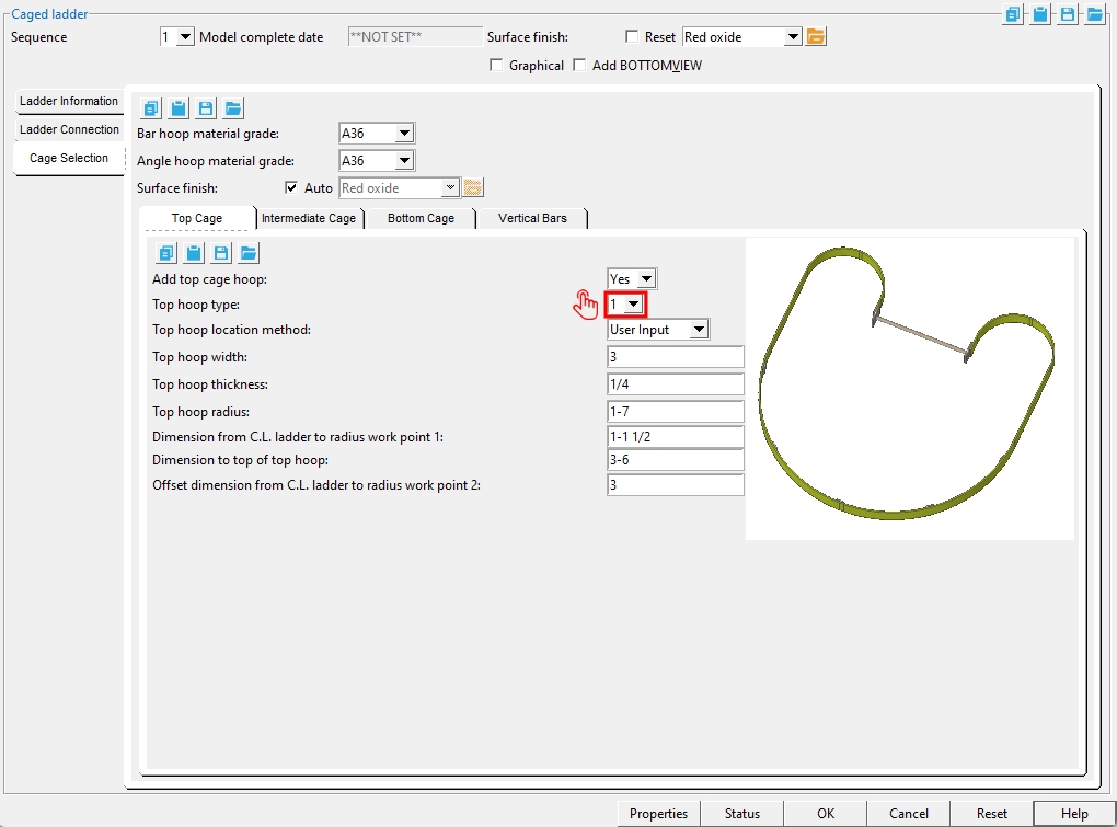
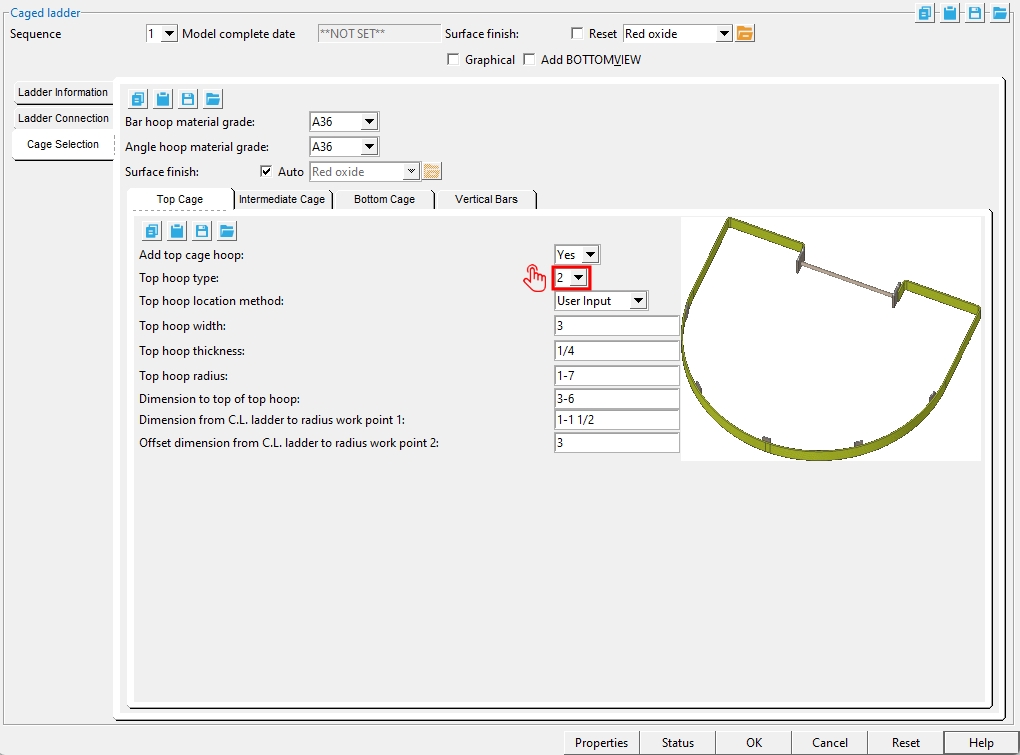
Cage Selection > Top Cage
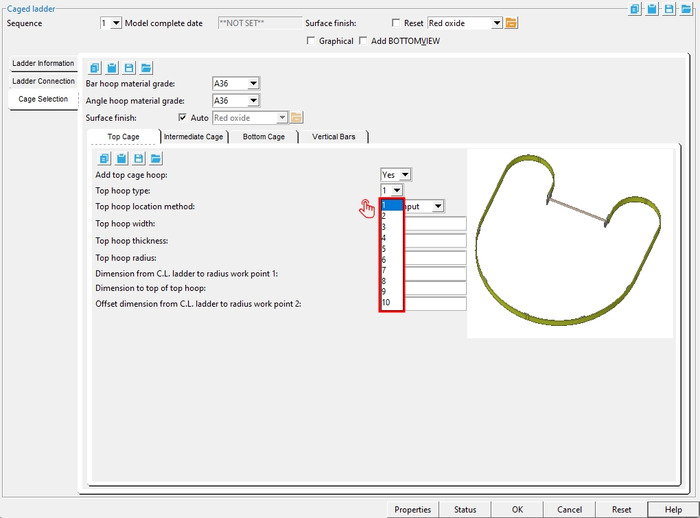
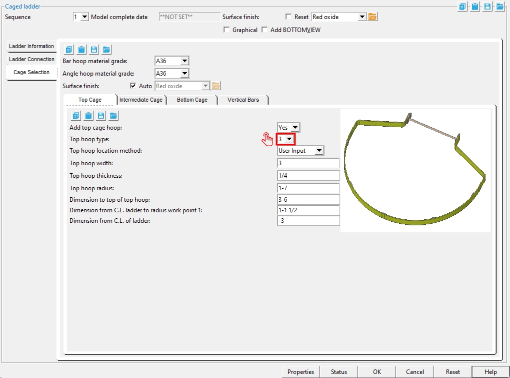
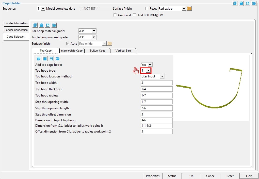
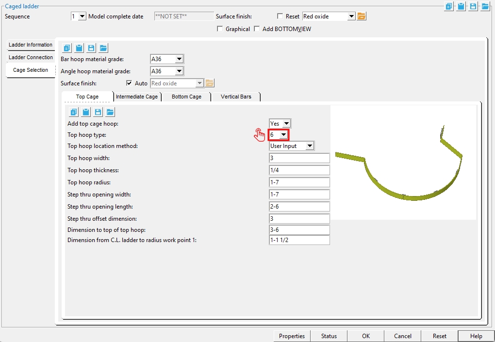
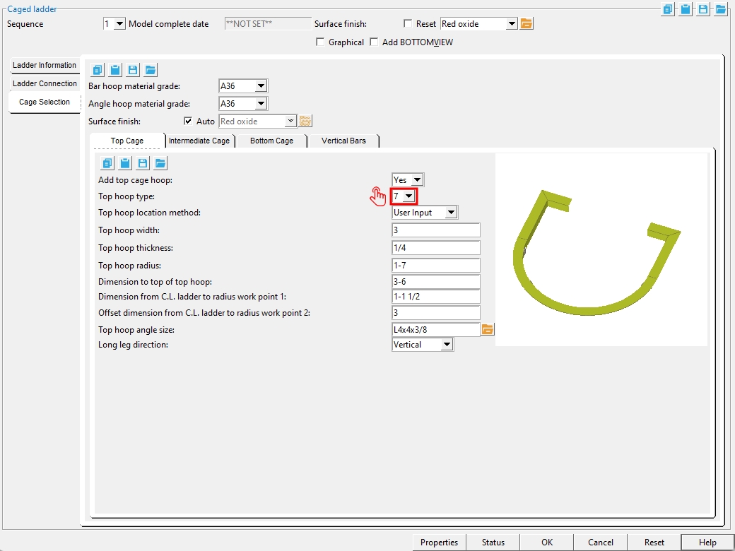
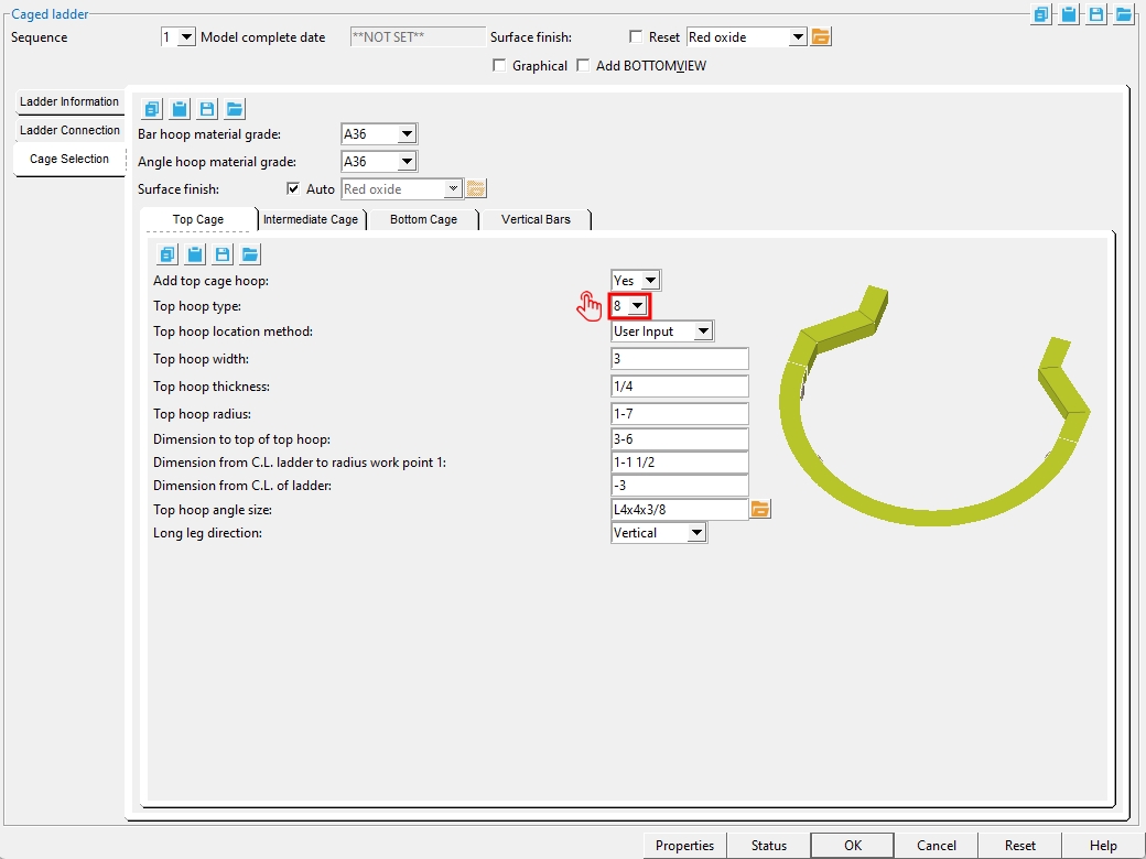
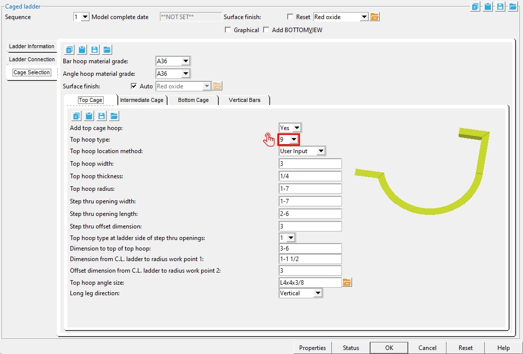
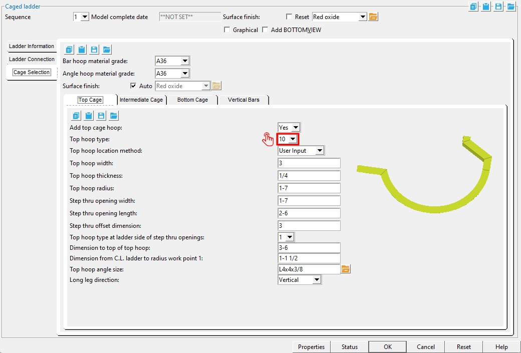
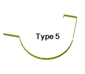
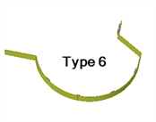
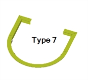
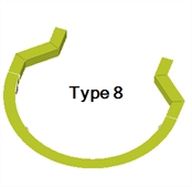
Top hoop type: The options available here depend on which Ladder type is selected.
Step Thru or Roof Hatch ladder types:
Top hoop types with bent plate layout: 1, 2, 3
Top hoop types with angle layout: 7, 8
Step Left or Step Right ladder types:
Top hoop types with bent plate layout: 4, 5, 6
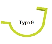
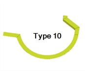
Top hoop types with angle layout: 9, 10
|
|
|
|
|
|
|
|
|
|
Top hoop location method: User Select or User Input.
'User Select' positions the top hoop based on the point that you locate when you press "OK" to close this window. At that time, the status line will prompt, "Locate top of top hoop". For a perfectly vertical ladder, you can left-click (Locate) when the target
( is at the elevation (Z coordinate on the X, Y, Z display) where you want the hoop. For a ladder that was input at an angle, you should locate a point along the ladder's work line.)
'User Input' positions the top hoop per to the "Dimension to top of top hoop".
Top hoop width: The distance that is the "Material width" of the bent plate layout material used to form a "Top hoop type" of 1 through 6.
Top hoop thickness: The distance that is the "Material thickness" of the bent plate layout material used to form a "Top hoop type" of 1 through 6.
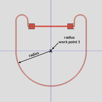
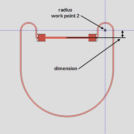
Top hoop radius: The radius of the top hoop is measured from the "Dimension from C.L. ladder to radius work point 1".
Dimension to top of top hoop: The distance measured from the finished floor to the top of the top hoop. The finished floor elevation is the elevation of the top flange of the beam that was located in step 2 plus the "Floor thickness at top of ladder". This dimension is parallel with the work line of the ladder and is vertical if the ladder is vertical. The dimension sets the top hoop location when 'User Input' is selected as the "Top hoop location method".
Dimension parallel from C.L. ladder to radius work point 2: Under Construction
Step thru opening width: The distance measured from the center of the ladder to the nearest face of material that makes the step thru opening in the top hoop of the cage.

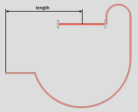
Step thru opening length: The distance measured from the center of the ladder to the end of material that makes the step thru opening in the top hoop of the cage.
Step thru offset dimension: The distance measured from the center of ladder to the nearest face of the step thru material attached to the ladder rail. A positive distance moves the material away from the front of the ladder. A negative distance moves the material toward the front of the ladder. 0 (zero) aligns the material with the center of the ladder.
Top hoop angle size: Type in any angle section size that is in the local shape file or press the "file cabinet" browse button )
Long leg direction: Vertical or Horizontal. This applies when the "Top hoop angle size" has unequal leg sizes.
'Vertical' makes the toe of the long leg of the angle as the vertically oriented inner-part of the hoop.
'Horizontal' makes the toe of the long leg of the angle as the horizontally oriented top-part of the hoop.
Top hoop type at ladder side of step thru opening: 1 (90° bend) or 2 (straight).
Cage Selection > Intermediate Cage
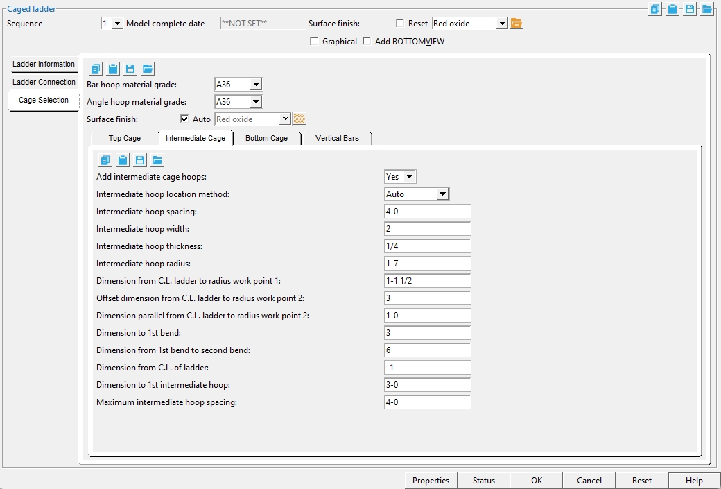
Add intermediate cage hoops: Yes or No.
Intermediate location method: Auto or User Select.
Auto: This location method uses the settings Dimension to 1st intermediate hoop and Maximum intermediate hoop spacing to locate the intermediate hoops. All measurements are taken from the center of the hoop's width. The default hoop type used for intermediate hoops is the "Bottom hoop type".
User Select: After you press "OK" to close this window, you will be prompted to locate the bottom of each intermediate hoop and to input its settings. When prompted to enter settings for each hoop, you can set the hoop type as well.
Intermediate hoop spacing: Under Construction
Intermediate hoop width: The distance that is the "Material width" of the bent plate layout material used to form an intermediate hoop.
Intermediate hoop thickness: The distance that is the "Material thickness" of the bent plate layout material used to form an intermediate hoop.
Intermediate hoop radius: The radius of the intermediate hoop is measured from the "Dimension from C.L. ladder to radius work point 1".
Dimension parallel from C.L. ladder to radius work point 2: Under Construction
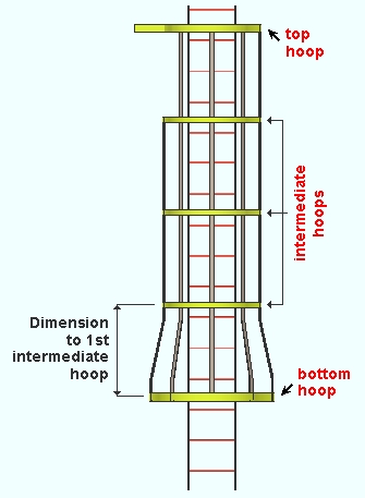
Dimension to 1st intermediate hoop: The distance measured vertically from the center of the bottom hoop's width to the center of the intermediate hoop's width.
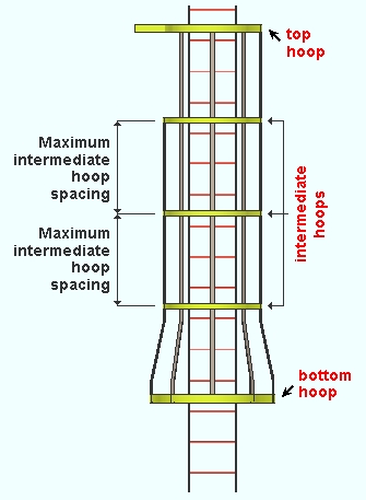
Maximum intermediate hoop spacing: The maximum distance measured vertically between the center of each intermediate hoop's width. This setting is applied when "Intermediate hoop location method" is set to Auto.
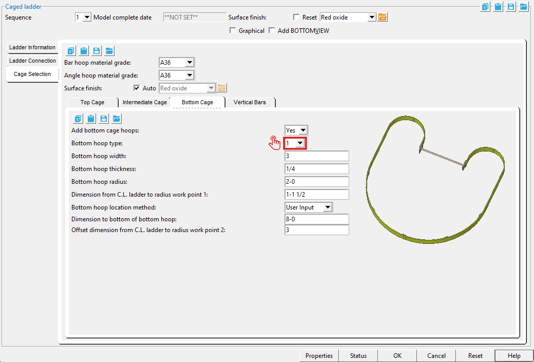
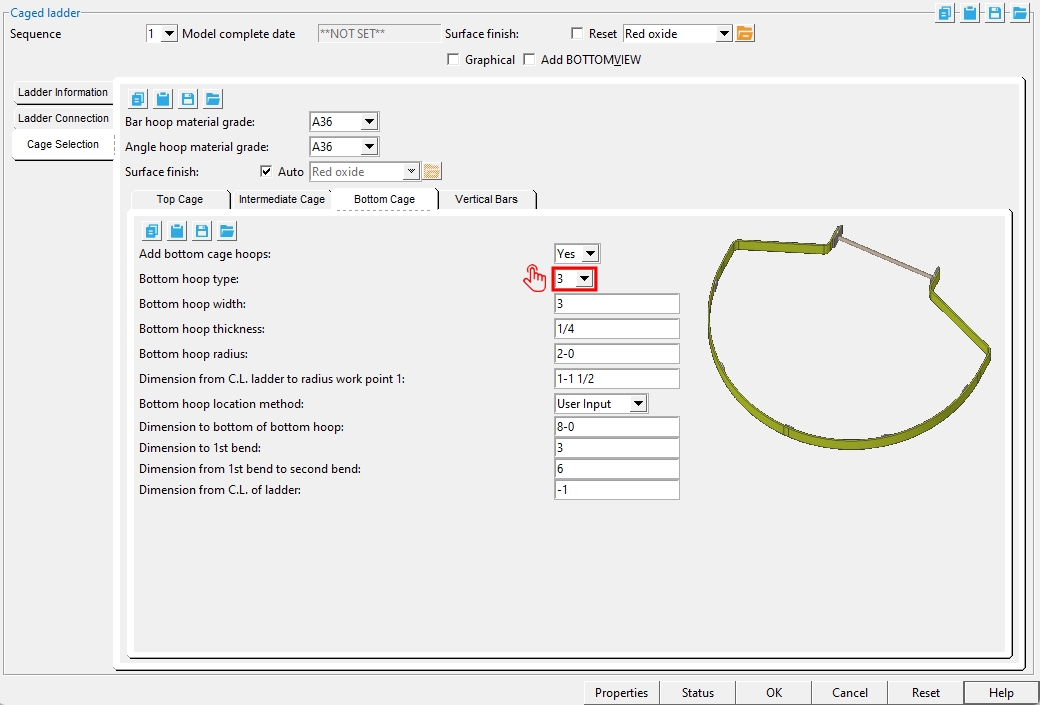
Cage Selection > Bottom Cage
Add bottom cage hoops: Yes or No. When Yes is selected, a bottom hoop is added to the cage. When No is selected, all cage components except for the top hoop are removed.
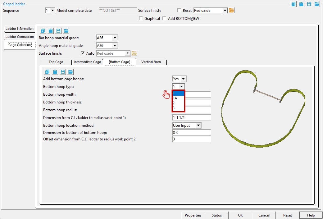
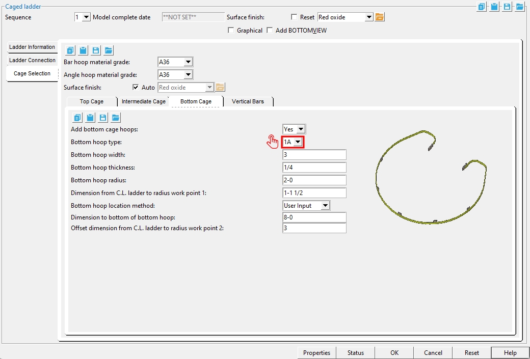
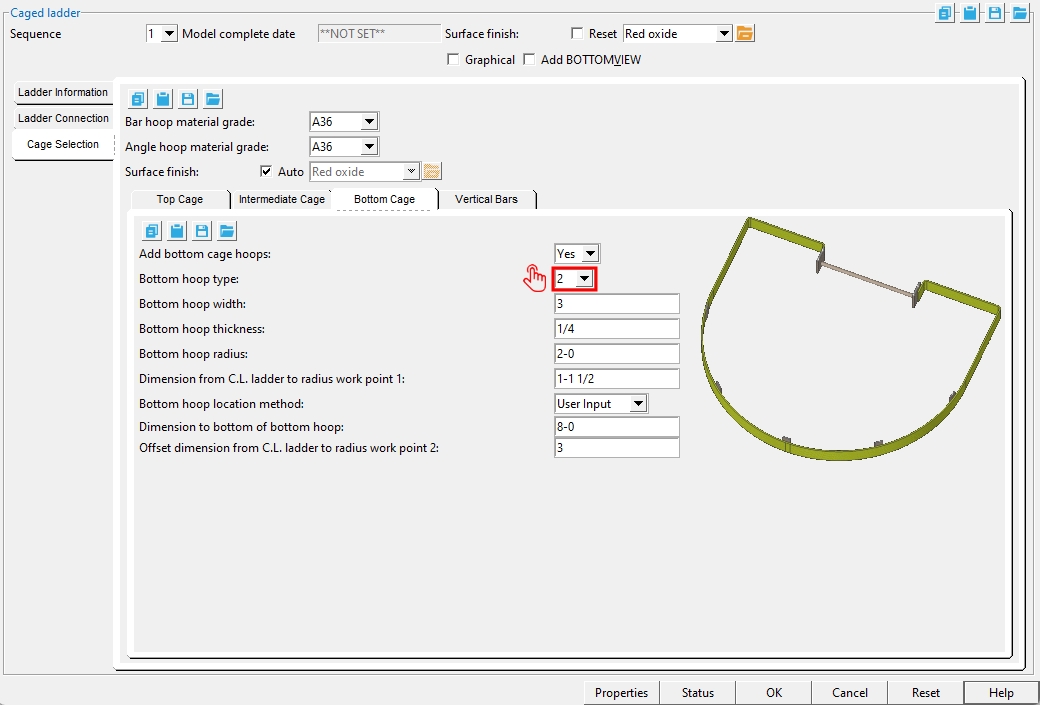
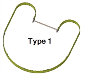
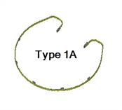
Bottom hoop type: Bent plate layout options 1, 1A, 2, or 3.
|
|
|
|
Bottom hoop width: The distance that is the "Material width" of the bent plate layout material used to form a bottom hoop.
Bottom hoop thickness: The distance that is the "Material thickness" of the bent plate layout material used to form a bottom hoop.
Bottom hoop radius: The radius of the bottom hoop is measured from the "Dimension from C.L. ladder to radius work point 1".
Dimension to bottom of bottom hoop: The distance from the bottom of the ladder's work line to the bottom of the bottom hoop.
Bottom hoop location method: User Select or User Input.
'User Select' positions the bottom hoop based on the point that you locate after you press "OK" to close this window. At that time, the status line will prompt, "Locate bottom of bottom hoop". For a perfectly vertical ladder, you can left-click (Locate) when the target
( is at the elevation (Z coordinate on the X, Y, Z display) where you want the bottom of the hoop. For a ladder that was input at an angle, you will probably want to locate your point along the ladder's work line.'User Input' positions the top hoop per the "Dimension to bottom of bottom hoop".
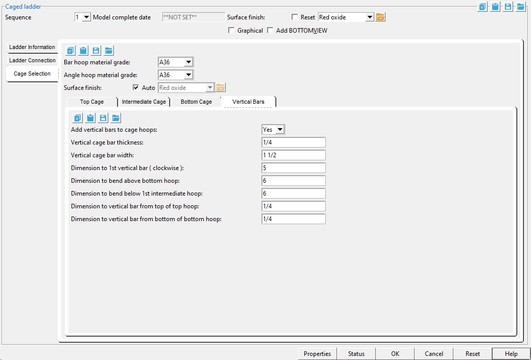
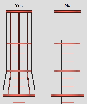
Cage Selection > Vertical Bars
Add vertical bars to cage hoops: Yes or No.
Vertical cage bar thickness: The distance that is the "Material thickness" of the bent plate layout material used to form a vertical bar.
Vertical cage bar width: The distance that is the "Material width" of the bent plate layout material used to form a vertical bar.
Dimension to 1st vertical bar (clockwise): The distance from the center line of the ladder to the center of the nearest vertical bar that is in the clockwise direction.
Dimension to bend above bottom hoop: The distance measured from the top of the bottom hoop to the first bend above it in the vertical bar. The measurement is referenced from the center of the bend in the bent plate layout material used to form the vertical bar.
Dimension to bend below 1st intermediate hoop: The distance measured from the bottom of the 1st intermediate hoop (located above the bottom hoop) to the first bend below it in the vertical bar. The measurement is referenced from the center of the bend in the bent plate layout material used to form the vertical bar.
Dimension to vertical bar from top of top hoop: The distance measured from the top of the top hoop to the top of the vertical bar.
Dimension to vertical bar from bottom of bottom hoop: The distance measured from the bottom of the bottom hoop to the bottom of the vertical bar.
Bar hoop material grade: This sets the "Steel grade" of bent plate layout material "Top hoop type" options 1-6 and all "Bottom hoop type" options.
Angle hoop material grade: This sets the "Steel grade" of angle material (rolled section material) "Top hoop type" options 7-10.
Surface Finish :None or Sandblasted or Red oxide or Yellow zinc or Gray oxide or Blued steel or Galvanized or Duplex Coating or Undefined 1 or Undefined 2 or Undefined 3 or Red oxide 2 or Any user added surface finish. This affects the colors of 'Solid' members on erection views in the Drawing Editor. This also sets the color when "Output material color" is set to 'Surface finish' for a VRML Export or a DWG/DXF Export. The "Color" (not"Surface finish") sets the color of this material in Modeling.
| sand blasted | red oxide | yellow zinc | user surface finish 1 |
| gray oxide | blued steel | galvanized | user surface finish 2 |
To assign a different surface finish, you can drop-down the current surface finish and select the one you want, or you can press the "file cabinet" browse button
( and double-click any surface finish that is on the list.
Dimension from C.L. ladder to radius work point 1:

Offset dimension from C.L. ladder to radius work point 2:
Dimension from C.L. of ladder:
Dimension from 1st bend to second bend:
1 . Click the Caged Ladder icon, which is pictured above. The icon can be found on the Members page > Steel section.
Alternative: Invoke Caged Ladder using the Find Tool by searching the command name and clicking the icon, which is pictured above.
Learn more about alternative methods for launching commands.
2 . The status line prompts, "Choose beam to connect to". Left-click (Select) the beam that is at the highest elevation along the span of the ladder. You can choose to connect to other beams below the highest one later on using the "Intermediate Connection Members" tab.
Alternative: Press the Esc key (or right-click and choose "Cancel") to decline to select a beam.
3 . Locate two points to establish the ladder's workline. A ladder's side rails run parallel with the work line. Its rungs run perpendicular to the work line. The ladder is centered around its work line.
3a: The status line prompts, "Locate bottom of ladder". Move your mouse pointer
( to place the point location target)
( where you want the bottom of the ladder, then left-click (Locate).3b: The status line prompts, "Locate top of ladder". Move your mouse pointer
( to place the point location target( where you want the top of the ladder, then left-click (Locate).
4. The Caged Ladder window opens. When are you are done changing or reviewing the settings in this window, press "OK" to close the Caged Ladder window.
Alternative: Press "Cancel" to close the Caged Ladder window and end the Add Caged Ladder operation. This stops the Caged Ladder member from being added to the model.
5. The operation repeats step 2. Repeat steps 2-4 to add another caged ladder member, or press the Esc key twice to end the operation.


.jpg)
.jpg)
.jpg)
.jpg)
.jpg)
.jpg)
.jpg)
.jpg)
.jpg)
.jpg)
.jpg)
.jpg)
.jpg)
.jpg)