Dimension Settings
- General Overview
- Tips and Tricks
- Related Tools
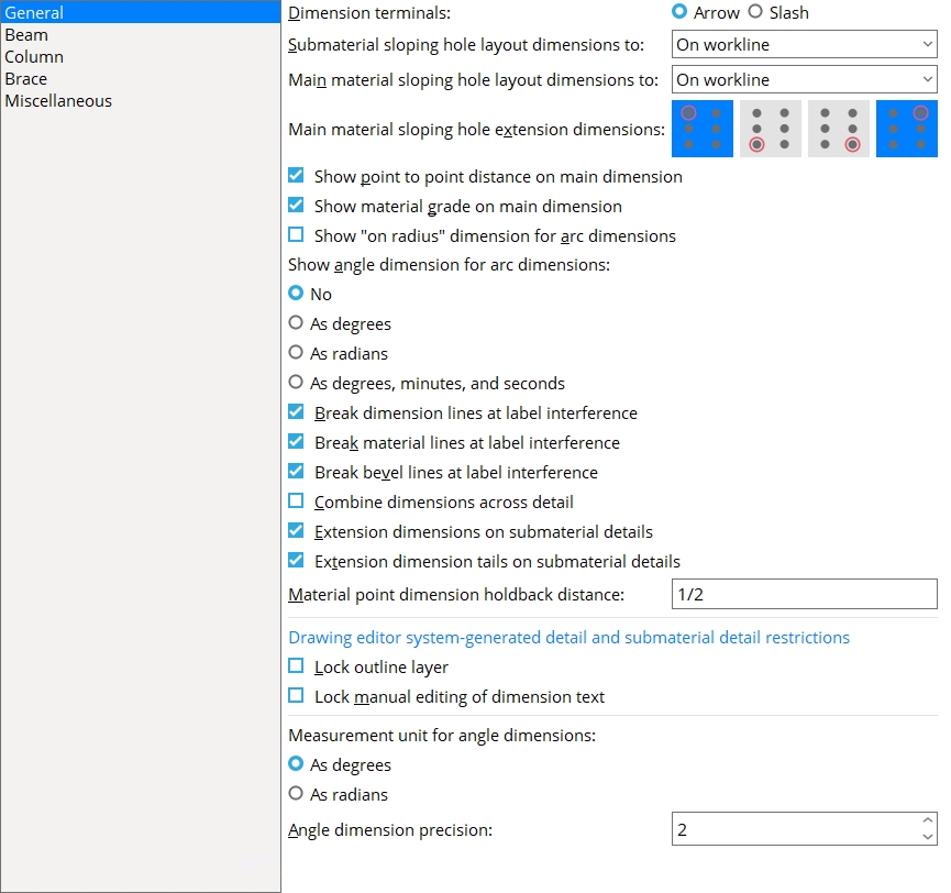
General
Dimension terminals: Arrow or Slash. The selection made here applies to all drawings that currently exist in your current Job as well as to yet-to-be-created drawings.
|
Note: If you change this setting, you do not have to re-detail. Your change is applied to currently generated drawings.
Submaterial sloping hole layout dimensions to: On workline or Farthest hole or Nearest hole or None. This sets the dimensioning reference point for the sloping hole group of a submaterial.
|
On workline refers to the member line of the framing member, not the member in the detail.
Farthest hole is the hole in the submaterial that is farthest from the workline of the member depicted in the detail.
Nearest hole is the hole that is closest to the member's workline.
None turns off dimensioning of this type.
Main material sloping hole layout dimensions to: On workline or Farthest hole or Nearest hole or None.
|
On workline refers to the work line of the framing member, not the member in the detail.
Farthest hole is the hole in the main material that is farthest from the work line of the member.
Nearest hole is the hole that is closest to the member's workline.
None turns off dimensioning of this type.
Tip: You can still select various Main material sloping hole extension dimensions if you like.
Main material sloping hole extension dimensions: Top, left hole and/or Bottom, left hole and/or Bottom, right hole and/or Top, right hole.
|


Note 1: These buttons control the dimension from the workline of the member to the hole as well as the position of the extension dimensions. When selected, the buttons turn blue. Any combination of the buttons may be selected.
Note 2: These options may be used when Main material sloping hole layout dimensions to is set to None or Farthest hole or etc.
Note 3: If one or more of these buttons are selected, Detail Members draws extension dimensions even if Show extension dimensions is not checked.
Show point to point distance on main dimension: ![]() or
or ![]() .
.
|
|||
| Point to point distance is the distance between the two work points of the member. It is equal to the overall dimension plus the minus dimension. |
If this box is checked (
), the point to point distance will be shown in parenthesis on the main dimension line on subsequently detailed members.
If the box is not checked (
), the point to point distance will not be shown.
Show material grade on main dimension: ![]() or
or ![]() .
.
|
If this box is checked (
If the box is not checked (
Show "on radius" dimension for arc dimensions: ![]() or
or ![]() . This applies when you Detail Members and when you Dimension Add Arc in the Drawing Editor.
. This applies when you Detail Members and when you Dimension Add Arc in the Drawing Editor.
|
If this box is checked (
If the box is not checked (
Show angle dimension for arc dimensions: No or As degrees or As radians or As degrees, minutes and seconds. This applies to all arc dimensions on subsequently auto detailed members and submaterials. It also applies when you Dimension Add Arc in the Drawing Editor.
No 
as Degrees
as Radians as Degr, Min, Sec No sets angle dimensions to not be displayed by default. In the Drawing Editor, you can override this setting on individual arc dimensions by checking the box for Angle in the Edit Arc Dimension window.
As degrees sets angle dimensions to be measured in degrees.
As radians sets angle dimensions to be measured in degrees.
As degrees, minutes, and seconds sets angle dimensions to be measured in degrees.
Note 1: If you change the angle unit setting from, for example, as Degrees to as Radians, currently generated drawings that display the arc dimension in degrees will not be changed until you do something that triggers the old measurement to be recalculated. For example, you could edit the dimension, turn off the display of angle dimensions, then turn their display back on.
Note 2: For arc dimensions on subsequently auto detailed members and submaterials, the settings As degrees and As radians and As degrees, minutes and seconds automatically check the box for
Break dimension lines at label interference: ![]() or
or ![]() .
.
|
If this box is checked (
To override this choice on individual drawings: The settings Breakable dimension leg(s) (Edit Dimension window) and Breaks lines (Label Edit window) and Breaks lines (Edit Dimension window) can be reset on details to override the breaking of lines.
If the box is not checked (
Tip: If you allow overlapping, you'll probably want to print labels and dimension labels with a wide pen. Home > Project Settings > Fabricator > Detailing > Line Weights lets you set up the line thickness per drawing pen.
Note: If you change this setting, you do not have to re-detail. Your change is applied to currently generated drawings.
Break material lines at label interference: ![]() or
or ![]() . The selection made here applies (when you press OK) to all drawings that currently exist in your current Job as well as to yet-to-be-created drawings.
. The selection made here applies (when you press OK) to all drawings that currently exist in your current Job as well as to yet-to-be-created drawings.
|
If this box is checked (
To override this choice on individual drawings: Breakable (Polygon Sides Edit window) and Breakable (Line Edit window) and Breaks lines (Label Edit window) and Breaks lines (Edit Dimension window) can be reset in the Drawing Editor to override the choice made here.
If the box is not checked (
Tip: If you allow overlapping, you'll probably want to print labels and dimension labels with a wide pen. Home > Project Settings > Fabricator > Detailing > Line Weights lets you set up the line thickness per drawing pen.
Note: If you change this setting, you do not have to re-detail. Your change is applied to currently generated drawings.
Break bevel lines at label interference:
![]() or
or ![]() . The selection made here applies (when you press OK) to all drawings that currently exist in your current Job as well as to yet-to-be-created drawings.
. The selection made here applies (when you press OK) to all drawings that currently exist in your current Job as well as to yet-to-be-created drawings.
|

If this box is checked (
To override this choice on individual drawings: Breakable (Bevel Symbol window) and Breaks lines (Label Edit window) and Breaks lines (Edit Dimension window) can be reset on details to override the choice made here.
If the box is not checked (
Tip: If you allow overlapping, you'll probably want to print labels and dimension labels with a wide pen. Home > Project Settings > Fabricator > Detailing > Line Weights lets you set up the line thickness per drawing pen.
Note: If you change this setting, you do not have to re-detail. Your change is applied to currently generated drawings.
Combine dimensions across detail: ![]() or
or ![]() .
.
|
If this box is checked (
If the box is not checked (
Extension dimensions on submaterial details: ![]() or
or ![]() .
.
|
If the box is checked (
( on the main view and, where appropriate, extension dimensions are drawn on the detail.)
Exception: When the submaterial detail of an angle does not show web near side as the main view, or if the detail shows material other than L, W, T, C, HSS round or HSS rectangular, Detail Submaterial does not draw an origin symbol.
If the box is not checked (
Extension dimension tails on submaterial details: ![]() or
or ![]() . This applies when you Detail Submaterial and the box is checked for Extension dimensions on submaterial details.
. This applies when you Detail Submaterial and the box is checked for Extension dimensions on submaterial details.
|
If this box is checked (
If the box is not checked (
Material point dimension holdback distance: Any distance from 0 to 2 inches (0 to 51 mm metric) that you want dimension legs set back from the material. The selection made here applies to all drawings that currently exist in your current Job as well as to yet-to-be-created drawings.
|
Note: If you change this setting, you do not have to re-detail. Your change is applied to currently generated drawings.
Drawing editor system-generated detail and submaterial detail restrictions
Lock outline layer:
![]() or
or ![]() . This applies to all automatically detailed member details and submaterial details in your current Job. Automatic detailing is not required to have this option applied.
. This applies to all automatically detailed member details and submaterial details in your current Job. Automatic detailing is not required to have this option applied.
|
If the outline layer is locked, users are unable to alter it. This ensures that materials on the detail exactly represent their appearance in the 3D model. |
If this box is checked (
If the box is not checked (
Warning: CNC downloads get their information from the 3D model, not from details. Do not make changes to details with the expectation that your changes will be reflected in CNC downloads.
Lock manual editing of dimension text: This applies to all dimensions on all automatically detailed member details and submaterial details in your current Job. Automatic detailing is not required to have this option applied. This does not apply to user-created member details, which can be created using the New Drawing command, Save As, or Save Reuse.
|
When the Label text is locked, other settings on the Edit Dimension window remain editable. |
If this box is checked (
If the box is not checked (
Measurement unit for angle dimensions: ![]() As degrees or
As degrees or ![]() As radians. An angle dimension includes Label text that is based on the arc between the two lines that the angle dimension is drawn between. Display measurement unit for angle dimensions sets whether the value for the Label text is calculated and expressed in degrees or radians.
As radians. An angle dimension includes Label text that is based on the arc between the two lines that the angle dimension is drawn between. Display measurement unit for angle dimensions sets whether the value for the Label text is calculated and expressed in degrees or radians.
|
as Degrees causes the Label text for newly added angle dimensions to be a number of degrees. The text will include the degree symbol (°).
Setup override: The Measurement units option on the Edit Angle Dimensions window is always set to the choice made here (Degrees or Radians) when an angle dimension is first added. After the angle dimension is added, the Measurement units can be changed.
Angle dimension precision:0 or 1 or 2 or 3 or 4. The number of places after the decimal point to which a calculated angle dimension will be rounded.
|
| Same Angle, Different Precisions | ||
| Precision | Degrees | Radians |
| 0 | 36 | 1 |
| 1 | 36.0 | 0.6 |
| 2 | 36.01 | 0.63 |
| 3 | 36.014 | 0.629 |
| 4 | 36.0140 | 0.6286 |
0 results in the angle dimension being expressed as a whole number. You might want to enter 0 as the precision if your Display measurement unit for angle dimensions is as Degrees.
1 results it the angle dimension being expressed with 1 place after the decimal point (e.g., 36.0 degrees or 0.6 radians).
2 results it the angle dimension being expressed with 1 place after the decimal point (e.g., 36.01 degrees or 0.63 radians). This is the default since it allows sufficient precision for switching between degrees and radians.
Tip: Since 2π radians = 360°, you will probably want more places after the decimal point when the Display measurement unit for angle dimensions is as Radians as opposed to when it is set to as Degrees.
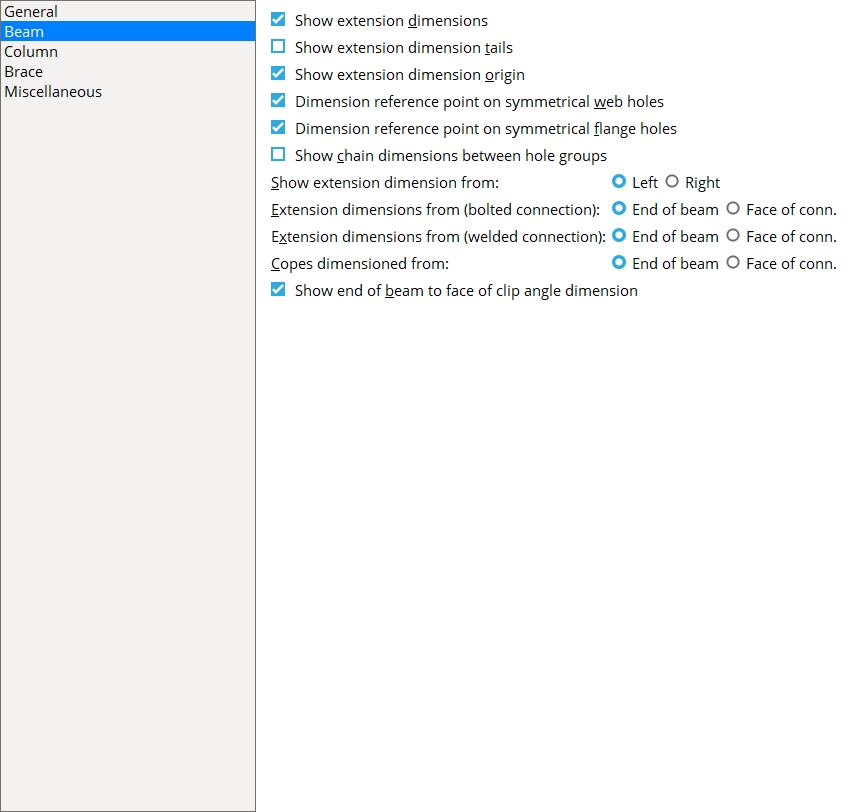
Beam
Show extension dimensions: ![]() or
or ![]() . Extension dimensions are also known as running dimensions.
. Extension dimensions are also known as running dimensions.
|
If this box is checked (
If the box is not checked (
Show extension dimension tails: ![]() or
or ![]() .
.
|
If this box is checked (
If the box is not checked (
Exception: In the case where omitting the tail would prevent the extension dimension from being drawn, the extension dimension will be drawn with a tail.
Effect on user-added dimensions: The default for Show tails, which applies to user-added dimensions, corresponds to the choice made here (checked or not checked) IF the drawing is a beam.
Show extension dimension origin: ![]() or
or ![]() .
.
|
If this box is checked (
( to designate the point of origin from which extension dimensions are measured.If the box is not checked (
Dimension reference point on symmetrical web holes: ![]() or
or ![]() .
.
|
If this box is checked (
If the box is not checked (
Tip: To find a hole group's dimensioning reference point in Modeling or change its placement, use Set Hole Reference Point.
Dimension reference point on symmetrical flange holes: ![]() or
or ![]() .
.
|
If this box is checked (
If the box is not checked (
Tip: To find a hole group's dimensioning reference point in Modeling or change its placement, use Set Hole Reference Point.
Show chain dimensions between hole groups: ![]() or
or ![]() .
.
|
If this box is checked (
If the box is not checked (
Show extension dimension from: Left or Right.
If Left is selected and Extension dimensions are designated to be drawn on beam details, then extension dimensions will be from the left end of the beam.
If Right is selected, dimensioning will be from the right end of the beam.
|
Extension dimensions from (bolted connection): End of beam or Face of conn. Extension dimensions for beams with bolted connections will be calculated from the position specified here.
|
||||
|
For both examples, the box is checked for |
Extension dimensions from (welded connection): End of beam or Face of conn. Extension dimensions for beams with welded connections will be calculated from the position specified here.
|
||||
|
For both examples, the box is checked for |
Copes dimensioned from: End of beam or Face of conn.
|
End of beam sets copes to be dimensioned from the end of the beam.
Face of conn sets copes to be dimensioned from the face of the connection (clip angle, end plate, etc.).
Show end of beam to face of clip angle dimension: ![]() or
or ![]() .
.
|
If this box is checked (
If the box is not checked (
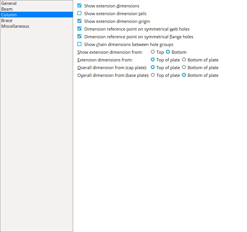
Column
Show extension dimensions: ![]() or
or ![]() . Extension dimensions are also known as running dimensions.
. Extension dimensions are also known as running dimensions.
|
If this box is checked (
If the box is not checked (
Show extension dimension tails: ![]() or
or ![]() .
.
|
If this box is checked (
If the box is not checked (
Exception: In the case where omitting the tail would prevent the extension dimension from being drawn, the extension dimension will be drawn with a tail.
Effect on user-added dimensions: The default for Show tails,which applies to user-added dimensions, corresponds to the choice made here (checked or not checked) IF the drawing is a column.
Show extension dimension origin: ![]() or
or ![]() .
.
|
If this box is checked (
( to designate the point of origin from which extension dimensions for columns are measured.If the box is not checked (
Dimension reference point on symmetrical web holes: ![]() or
or ![]() .
.
|
If this box is checked (
If the box is not checked (
Tip: To find a hole group's reference point in Modeling or change its placement, use the Set Hole Reference Point command.
Dimension reference point on symmetrical flange holes: ![]() or
or ![]() .
.
|
If this box is checked (
If the box is not checked (
Tip: To find a hole group's reference point in Modeling or change its placement, use the Set Hole Reference Point command.
Show chain dimensions between hole groups: ![]() or
or ![]() .
.
If the box is checked (
|
Show extension dimensions from: Top or Bottom.
|
If Top is selected, the point of origin for extension dimensions newly generated during auto detailing will be from the top of the column.
If Bottom is selected, the point of origin will be from the bottom of the column.
Extension dimensions from: Top of plate or Bottom of plate.
|
Top of plate instructs auto detailing to calculate the extension dimension from the top of the cap plate if extension dimensions are designated to be taken from the top of the column. If extension dimensions are taken from the bottom of the column, they will be measured from the top of the base plate.
Bottom of plate instructs auto detailing to calculate the extension dimension from the bottom of the base plate when extension dimensions are designated to be taken from the bottom of the column and If extension dimensions are taken from the top of the column, they will be measured from the bottom of the cap plate.
Overall dimensions from (cap plate): Top of plate or Bottom of plate.
|
Top of plate sets the overall dimension of the column to be calculated from the top of the cap plate for automatically detailed member details of columns.
Bottom of plate sets the overall dimension of the column to be calculated from the bottom of the cap plate.
Overall dimensions from (base plate): Top of plate or Bottom of plate.
|
Top of plate sets the overall dimension to be calculated from the top of the base plate.
Bottom of plate sets the overall dimension of the column to be calculated from the bottom of the base plate for automatically detailed member details of columns.
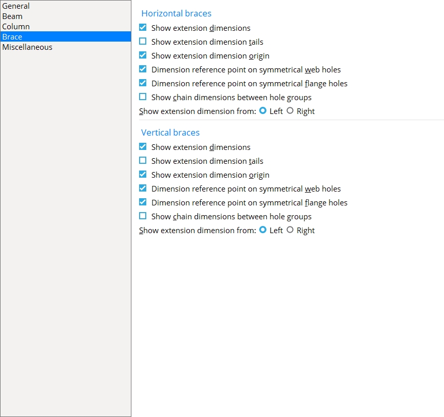
Brace
Horizontal braces
Show extension dimensions: Extension dimensions are also known as running dimensions.
|
If this box is checked (
If the box is not checked (
Show extension dimension tails: ![]() or
or ![]() .
.
|
If this box is checked (
If the box is not checked (
Exception: In the case where omitting the tail would prevent the extension dimension from being drawn, the extension dimension will be drawn with a tail.
Effect on user-added dimensions: The default for Show tails,which applies to user-added dimensions, matches the choice made here (checked or not checked) if the drawing is a horizontal brace.
Show extension dimension origin: ![]() or
or ![]() .
.
|
If this box is checked (
( to show the point of origin for extension dimensions on horizontal braces.If the box is not checked (
Dimension reference point on symmetrical web holes: ![]() or
or ![]() .
.
|
If this box is checked (
If the box is not checked (
Tip: To find a hole group's reference point in Modeling or change its placement, use Set Hole Reference Point.
Dimension reference point on symmetrical flange holes: ![]() or
or ![]() .
.
|
If this box is checked (
If the box is not checked (
Tip: To find a hole group's reference point in Modeling or change its placement, use Set Hole Reference Point.
Show chain dimensions between hole groups: ![]() or
or ![]() .
.
|
If this box is checked (
If the box is not checked (
Show extension dimensions from: Left or Right.
If Left is selected, then the point of origin for an extension dimension on a horizontal brace detail newly generated during automatic detailing will be from the left end of the brace.
If Right is selected, then the point of origin for an extension dimension on a horizontal brace detail newly generated during automatic detailing will be from the right end of the brace.
| Extension dimensions from left: |
|
| Extension dimensions from right: |
|
Vertical braces
Show extension dimensions: ![]() or
or ![]() . Extension dimensions are also known as running dimensions.
. Extension dimensions are also known as running dimensions.
|
If this box is checked (
If the box is not checked (
Show extension dimension tails: ![]() or
or ![]() .
.
|
If this box is checked (
If the box is not checked (
Exception: In the case where omitting the tail would prevent the extension dimension from being drawn, the extension dimension will be drawn with a tail.
Effect on user-added dimensions: The default for Show tails,which applies to user-added dimensions, matches the choice made here (checked or not checked) if the drawing is a vertical brace.
Show extension dimension origin: ![]() or
or ![]() .
.
|
If this box is checked (
( to show the point of origin for extension dimensions on vertical braces.If the box is not checked (
Dimension reference point on symmetrical web holes: ![]() or
or ![]() .
.
|
If this box is checked (
If the box is not checked (
Tip: To find a hole group's reference point in Modeling or change its placement, use Set Hole Reference Point.
Dimension reference point on symmetrical flange holes: ![]() or
or ![]() .
.
|
If this box is checked (
If the box is not checked (
Tip: To find a hole group's reference point in Modeling or change its placement, use Set Hole Reference Point.
Show chain dimensions between hole groups: ![]() or
or ![]() .
.
|
If this box is checked (
If the box is not checked (
Show extension dimensions from: Left or Right.
If Left is selected, then the point of origin for an extension dimension on a vertical brace detail newly generated during automatic detailing will be from the left end of the brace.
If Right is selected, then the point of origin for an extension dimension on a vertical brace detail newly generated during automatic detailing will be from the right end of the brace.
| Extension dimensions from left: |
|
|
| Extension dimensions from right: |
|
|
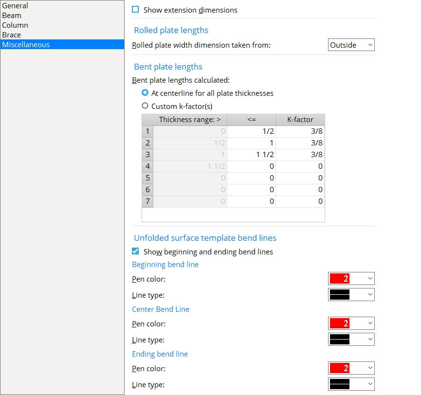
Miscellaneous
Show extension dimension: ![]() or
or ![]() .
.
|
If this box is checked (
If the box is not checked (
Rolled plate lengths
Rolled plate width dimension taken from: Outside or Center or Inside. This affects the Unrolled width of a rolled plate and is used in the material Description on the General Information window and in the Description in the member bill of material. The Unrolled width of the plate is also included in the plate section callout on the plate's submaterial detail.
| Outside | Center | Inside |
|
|
|
Outside causes the Unrolled width of the rolled plate to be measured along the outside arc of the roll.
Center causes the Unrolled width of the rolled plate to be measured along the neutral axis of the rolled plate.
Inside causes the Unrolled width of the rolled plate to be measured along the inside arc of the roll.
Bent plate lengths
Bent plate lengths calculated: ![]() At centerline for all plate thickness or
At centerline for all plate thickness or ![]() Custom k-factor(s).. The choice made here affects the Description on the General Information window in Modeling and the Description in the member bill of material. Lengths of bent plates in CNC download files are also based on the choices made here.
Custom k-factor(s).. The choice made here affects the Description on the General Information window in Modeling and the Description in the member bill of material. Lengths of bent plates in CNC download files are also based on the choices made here.
|
A K factor is a ratio that quantifies how the thickness of a bent plate material is distributed around its neutral axis. Note: If you were to choose Custom K factors and to enter 0.5 for all K factor entries on the table, the results you would get would be the same as if you were to choose At centerline for all plate thicknesses. This is because a K factor of 0.5 indicates that the neutral axis is at the exact center of the thickness.
Unfolded surface template bend lines
Show beginning and ending bend lines: or .
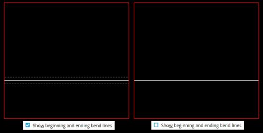
If this box is checked (
If the box is not checked only the center bend line is shown on the unfolded surface template.
Beginning bend line
Pen Color : The color of the line added where the plates bend begins.

Line Type : The dash pattern of the line added where the plates bend begins.

Center bend line:
Pen Color : The color of the line added where the plates bend begins.
Line Type : The dash pattern of the line added where the plates bend begins.
Ending bend line:
Pen Color : The color of the line added where the plates bend begins.
Line Type : The dash pattern of the line added where the plates bend begins.


|
|
OK (or the Enter key) closes this screen and applies the settings.
Cancel (or the Esc key) closes this screen without saving any changes.
Reset undoes all changes made to this screen since you first opened it. The screen remains open.