Drawing Presentation
- General Overview
- Tips and Tricks
- Related Tools
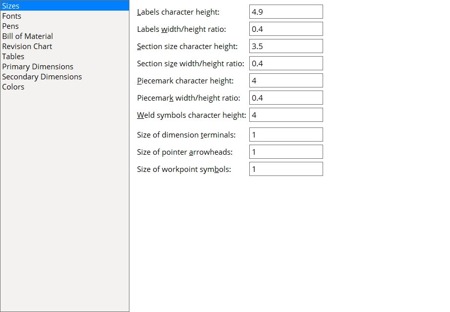
Sizes
These settings apply during the detailing of members and/or submaterials and/or erection views. Make entries here before automatic detailing.
Labels character height: The height (millimeters) of the characters that make up labels and to text in hole symbols. This value is independent of the Drawing scale of a drawing. Assuming that the sheet a drawing is placed on has a scale of 1:1 and you do not re-scale the labels and the printer does not adjust the scale, this will be the actual height of characters on the plotted sheet.
|
Effect on auto detailing: The character height entered here applies to labels on details whose piecemarks you select when you Detail Members or Detail Submaterial. A character height of 3.5 millimeters is ideal in most cases.
Font dependencies: The entry made here applies to whatever font is selected as the Label font, regardless of whether that font is a TrueType font or the SDS2 font.
Labels width/height ratio: The width-to-height ratio to be applied to labels and to text in hole symbols. All characters in the following example have the same character height, but each line has a different character width/height ratio.
|
Tip: The entry made here applies to whatever font is selected as the Label font, regardless of whether that font is a TrueType font or the SDS2 font. Set this to 0.6 for a TrueType font. For the SDS2 font, 0.4 is a good choice.
Effect on auto detailing: The ratio entered here applies to details whose piecemarks you select when you Detail Members or Detail Submaterial. An entry of .5 designates characters 1/2 as wide as they are tall.
Section size character height: The character height (millimeters) of section sizes on a 2D erection view. Assuming that the sheet a drawing is placed on has a scale of 1:1 and you do not re-scale the labels and the printer does not adjust the scale, this will be the actual height of characters on the plotted sheet. This also affects the relative size of section sizes with respect to members in Modeling.
|
Tip: You can change the section size character height on a 2D erection view using Erection View Cleanup.
Effect on Detail Erection Views: The character height entered here applies to section size lettering on 2D erection views when you Detail Erection Views. The height is independent of the Drawing scale of the erection view. This means that if you change the Drawing scale, the section sizes remain the same size (when plotted) even though the scale of the members changes. Similarly, if you increase the Display scale of a view (in Modeling), the section sizes in that view will appear to grow smaller, but when you redetail that view and print it, the section sizes will be exactly the height you have specified here.
Font dependencies: This applies to whatever font is selected as the Member labels font, regardless of whether that font is a TrueType font or the SDS2 font.
Section size width/height ratio: The width-to-height ratio to be applied to section sizes on a 2D erection view. An entry of .5 designates characters 1/2 as wide as they are tall. This also affects the relative size of section sizes with respect to members in Modeling.
|
Tip 1: The ratio entered here applies to whatever font is selected as the Member labels font, regardless of whether that font is a TrueType font or the SDS2 font. Set this to 0.6 for a TrueType font. For the SDS2 font, 0.4 is a good choice.
Tip 2: You can change the section size character width/height ratio on a 2D erection drawing using Erection View Cleanup.
Effect on Detail Erection Views: The ratio entered here applies to section size lettering on erection view drawings when you Detail Erection Views. The width you enter here is independent of the Drawing scale of the erection view drawing. If you change the scale of a drawing without choosing to rescale the labels, then print it, the section sizes on the actual printed erection view will be the height entered to Section size character height and the width you have entered here.
Piecemark character height: The height (millimeters) of piecemarks on a 2D erection view. Assuming that the sheet a drawing is placed on has a scale of 1:1 and you do not re-scale the labels and the printer does not adjust the scale, this will be the actual height of characters on the plotted sheet. This also affects the relative size of piecemarks with respect to members in Modeling.
|
Tip: You can change the piecemark character height on a 2D erection drawing using Erection View Cleanup.
Effect on Detail Erection Views: The character height entered here applies to piecemark lettering on 2D erection views when you Detail Erection Views. The height is independent of the Drawing scale of the erection view. This means that if you change the Drawing scale, the piecemarks remain the same size (when plotted) even though the scale of the members changes. Similarly, if you increase the Display scale of a view (in Modeling), the piecemarks in that view will appear to grow smaller. When you redetail and plot that view, the piecemarks will be exactly the height you have specified here.
Font dependencies: This Sizes screen option applies to whatever font is selected as the Member labels font, regardless of whether that font is a TrueType font or the SDS2 font.
Piecemark width/height ratio: The width-to-height ratio to be applied to piecemarks on a 2D erection view. An entry of .5 designates characters 1/2 as wide as they are tall. This also affects the relative size of piecemarks with respect to members in Modeling.
|
Tip 1: The ratio entered here applies to whatever font is selected as the Member labels font, regardless of whether that font is a TrueType font or the SDS2 font. For a TrueType font, set this to 0.6. For the SDS2 font, 0.4 is a good choice.
Tip 2: You can change the piecemark width/height ratio on a 2D erection drawing using Erection View Cleanup.
Effect on Detail Erection Views: The ratio entered here applies to piecemarks on erection view drawings when you Detail Erection Views. The width is independent of the Drawing scale of the erection view drawing. If you change the scale of a drawing without choosing to rescale the labels, and then print it, the piecemarks on the actual printed erection view will be the height entered to Piecemark character height and the width you have entered here.
Weld symbols character height: The weld symbol character height (millimeters).
Effect: The character height entered here applies to weld symbols that are automatically generated when you Detail Members. It also sets the default Character height on the Weld Input window when you first Weld Add in the Drawing Editor.
Font dependencies: This applies to whatever font is selected as the Symbols font, regardless of whether that font is a TrueType font or the SDS2 font.
Size of dimension terminals: A number less than 1 or 1 or a number greater than 1. This sets the size for all dimension terminals in drawings of members, submaterials, and erection views that are subsequently generated during auto detailing. This option also sets the default size of terminals on dimensions that are subsequently added to drawings of any type. For old drawings, newly added dimensions use the terminal size that is already established for dimensions in those drawings.
| A green label indicates each dimension's terminal size. | |||||
|
Dimension terminals in set to Arrow. | ||||
|
Dimension terminals in set to Slash. | ||||
A number less than 1 reduces the size of dimension terminals relative to a terminal size of 1. For example, a size .5 terminal is 1/2 the size of a size 1 terminal. A size .75 terminal is 3/4 the size of a size 1 terminal.
1 is the standard size of dimension terminals. Dimension terminals can be scaled on individual dimensions or groups of dimensions using Size of dimension terminals on the Edit Dimension window.
A number greater than 1 increases the size of dimension terminals relative to what their size 1 size would be. For example, a size 1.5 terminal is 1 1/2 times the size of a size 1 terminal. A size 2 terminal is 2 times the size of a size 1 terminal.
To override the size entered here: You can alter dimension terminal sizes on individual dimensions using the Size of dimension terminals option on the Edit Dimension window.
Size of pointer arrowheads: A number less than 1 or 1 or a number greater than 1. This sets the size for all pointer arrowheads in drawings of members, submaterials, and erection views that are subsequently generated during auto detailing. This option also sets the default size of arrowheads on pointers that are subsequently added (using operations such as Pointer Add) to drawings with no pointers already in them. To keep pointer heads consistently sized on old drawings, newly added pointers use the scale that is already established for pointers in those drawings.
|
A number less than 1 reduces the size of pointer arrowheads relative to an arrowhead size of 1. For example, a size .5 arrowhead is 1/2 the size of a size 1 arrowhead. A size .75 arrowhead is 3/4 the size of a size 1 arrowhead.
1 is the standard size of an arrowhead. Arrowheads can be scaled on individual pointers or groups of pointers using Size of arrowhead on the Pointer Edit window.
A number greater than 1 increases the size of pointer arrowheads relative to what their size 1 size would be. For example, a size 1.5 arrowhead is 1 1/2 times the size of a size 1 arrowhead. A size 2 arrowhead is 2 times the size of a size 1 arrowhead.
To override the size entered here: You can alter individual pointer arrowheads using the Size of arrowhead option on the Pointer Edit window.
Size of workpoint symbols: A number less than 1 or 1 or a number greater than 1. This sets the size for all workpoint symbols in drawings of members that are subsequently generated during auto detailing. It also sets the size of workpoints that are subsequently added using operations such as Workpoint Add.
|
A number less than 1 reduces the size of workpoint symbols relative to a symbol size of 1. For example, a size .5 symbol is 1/2 the size of a size 1 symbol. A size .75 symbol is 3/4 the size of a size 1 symbol.
1 is the standard size of workpoint symbol. Workpoint symbols can be scaled using Symbol size on the Workpoint Edit window.
A number greater than 1 increases the size of workpoint symbols relative to what their size 1 size would be. For example, a size 1.5 symbol is 1 1/2 times the size of a size 1 symbol. A size 2 symbol is 2 times the size of a size 1 symbol.
To override the size entered here: You can alter individual workpoint symbols using the Symbol size option on the Workpoint Edit window.
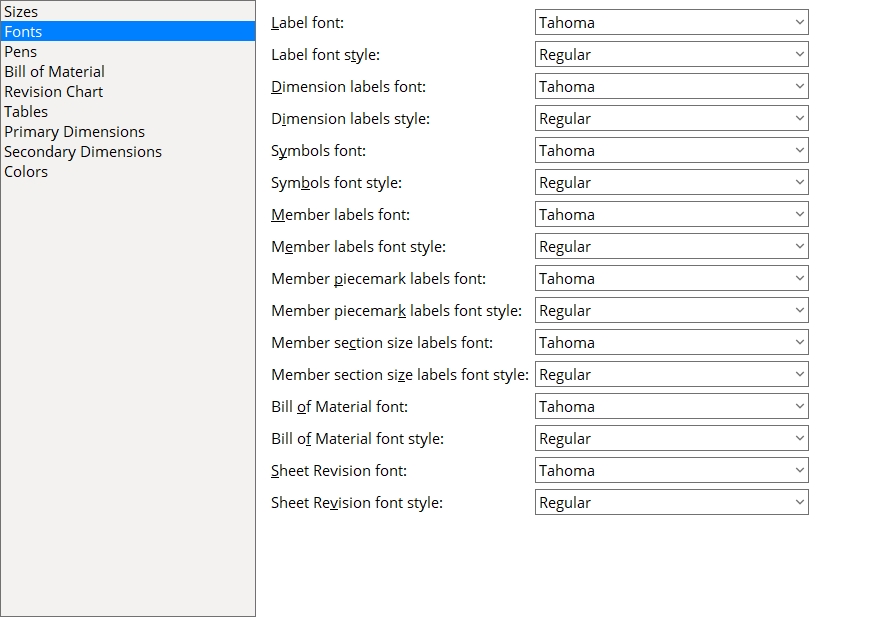
Fonts
Label font: Any font that is listed can be selected. The choice made here applies to labels that are generated during auto detailing with or without templates. It also sets the default font for the first label that is added to a drawing in a Drawing Editor session using Label Add. Labels subsequently added in that same session will use the font applied to the last-added or last-edited label. Be sure to also choose the Label font style that you want.
|
The color green identifies labels in this example. Labels should not be confused with the text that is a part of bevel symbols, dimensions, or weld symbols. |
Label font style: The style (Bold or Bold Italic or Italic or Regular) of the selected Label font. Different fonts have different styles available to them.
Available font styles are listed alphabetically in the font style list box, and the first style that is listed for a particular font is the style that is selected by default. Instead of using the default you may prefer to choose Regular, which is generally the most popular style for a particular font. Regular is the only choice that is available for the SDS2 font. To adjust the stroke thickness for the SDS2 font change the Detailing label pen color.
Also see: The Edit Label window has Font and Font style options which you can use to apply different fonts to individual incidences of labels.
Dimension labels font: Any font that is listed can be selected. This applies to dimension labels that are generated during auto detailing. It also sets the default font for dimensions added using tools such as Dimension Add. Be sure to also choose the Dimension labels font style that you want.
|
The color green identifies dimension labels in this example. |
Dimension labels style: The style (Bold or Bold Italic or Italic or Regular) of the selected Dimension label font.
Available font styles are listed alphabetically in the font style list box, and the first style that is listed for a particular font is the style that is selected by default. Instead of using the default you may prefer to choose Regular, which is generally the most popular style for a particular font. Regular is the only choice that is available for the SDS2 font. To adjust the stroke thickness for the SDS2 font change the Dimension pen color on the Pens screen.
Also see: The Dimension Edit and Edit Arc Dimension windows have options for applying a Font and Font style to the primary dimension label. Similar options are available on these windows for the secondary dimension label.
Symbols font: Any font that is listed can be selected. This applies to the text used for bevel symbols and weld symbols. Be sure to also choose the Symbols font style that you want.
|
|||||
|
Symbols font style: The style (Bold or Bold Italic or Italic or Regular) of the selected Symbols font.
Available font styles are listed alphabetically in the font style list box, and the first style that is listed for a particular font is the style that is selected by default. Instead of using the default you may prefer to choose Regular, which is generally the most popular style for a particular font. Regular is the only choice that is available for the SDS2 font. To adjust the stroke thickness for the SDS2 font, change the Weld pen color and Bevel pen color on the Pens screen.
Also see: The Bevel Symbol and Weld Input windows have Label font and Label font style options which you can use to apply different fonts to individual incidences of labels.
Member labels font: Any font that is listed can be selected. Member labels include camber annotations, elevations and ABM page-lines. Be sure to also choose the Member label font style that you want.
|
The member labels in this example are elevations. They are shown in the color green. |
Member labels font style: The style (Bold or Bold Italic or Italic or Regular) of the selected Member labels font. Different fonts may have different styles available to them.
Available font styles are listed alphabetically in the font style list box, and the first style that is listed for a particular font is the style that is selected by default. Instead of using the default you may prefer to choose Regular, which is generally the most popular style for a particular font. Regular is the only choice that is available for the SDS2 font.
Member piecemark labels font: Any font that is listed can be selected. Member piecemark labels can include member numbers as well as member piecemarks. Be sure to also choose the Member piecemark labels font style that you want.
|
The member piecemark labels in this example are shown in the color green. Member numbers are shown with the piecemarks when the option to show |
Member piecemark labels font style: The style (Bold or Bold Italic or Italic or Regular) of the selected Member piecemark labels font. Different fonts may have different styles available to them.
Available font styles are listed alphabetically in the font style list box, and the first style that is listed for a particular font is the style that is selected by default. Instead of using the default you may prefer to choose Regular, which is generally the most popular style for a particular font. Regular is the only choice that is available for the SDS2 font. To adjust the stroke thickness for piecemark labels in the SDS2 font, change the Piecemark pen color on the Pens screen.
Member section size labels font: Any font that is listed can be selected. Member section size labels are section sizes. Be sure to also choose the Member section size label font style that you want.
|
The member section size labels in this example are shown in the color green. |
Member section size labels font style: The style (Bold or Bold Italic or Italic or Regular) of the selected Member section size labels font. Different fonts may have different styles available to them.
Available font styles are listed alphabetically in the font style list box, and the first style that is listed for a particular font is the style that is selected by default. Instead of using the default you may prefer to choose Regular, which is generally the most popular style for a particular font. Regular is the only choice that is available for the SDS2 font. To adjust the stroke thickness for section size labels in the SDS2 font, change the Section size pen color on the Pens screen.
Bill of material font: Any font that is listed can be selected as the font for bill data text. Bill data is compiled into a bill of material when you Sheet Item Add to a sheet with a bill. It can also be compiled via operations such as Detail Sheet Autoload. The font that is selected here is the default Bill font.
|
|||
| The Bill of material font applies to the information compiled into the bill when you Sheet Item Add (ONE B_14 BEAM...). In this example, the color of the bill data is white. |
Be sure to also choose the Bill of material font style that you want.
Editing a bill: In the Drawing Editor, you can double-click a placed bill of material and change its Bill font.
Also see: Title font sets the font for the title (e.g., BILL OF MATERIAL) for subsequently placed bills of material. The Header font sets the font used for headers (e.g., LINE #, QTY TOTAL, etc.).
Bill of material font style: The style (Bold or Bold Italic or Italic or Regular) of the selected Bill of material font. Different fonts may have different styles available to them.
Available font styles are listed alphabetically in the font style list box, and the first style that is listed for a particular font is the style that is selected by default. Instead of using the default you may prefer to choose Regular, which is generally the most popular style for a particular font. Regular is the only choice that is available for the SDS2 font. To adjust the stroke thickness for the SDS2 font, change the Bill label pen color.
Changing the bill font style on an individual bill of material: This sets the default Bill font style that is applied to a bill of material. Once a bill has been placed, you can double-click that bill of material and change its Bill font style.
Sheet revision font: Any font that is listed can be selected. The font that is selected applies to the revision line text, not to the column title text. This sets the default Font that will be applied to new revision charts subsequently placed onto a sheet or sheet outline using Place Revision Chart.
|
|||
| The green-colored text in the revision chart shown above is plotted in the Sheet revision font that is selected here. |
Revision line text may be entered to a revision chart using the Sheet Revision Chart Editor.
Be sure to also choose the Sheet revision font style that you want. The Character height and Character width/height ratio options on the Revision Chart screen set the font size.
Overriding the choice made here: The Font can be changed on the edit window for an individual revision chart.
Sheet revision font style: The style (Bold or Bold Italic or Italic or Regular) of the selected Sheet revision font. Different fonts may have different styles available to them. Regular is the only choice that is available for the SDS2 font.
Available styles are listed alphabetically in the font style list box, and the first style that is listed for a particular font is the style that is selected by default. Instead of using the default you may prefer to choose Regular, which is generally the most popular style for a particular font. Regular is the only choice that is available for the SDS2 font. To adjust the stroke thickness for the SDS2 font, change the Bill label pen color on the Pens screen.
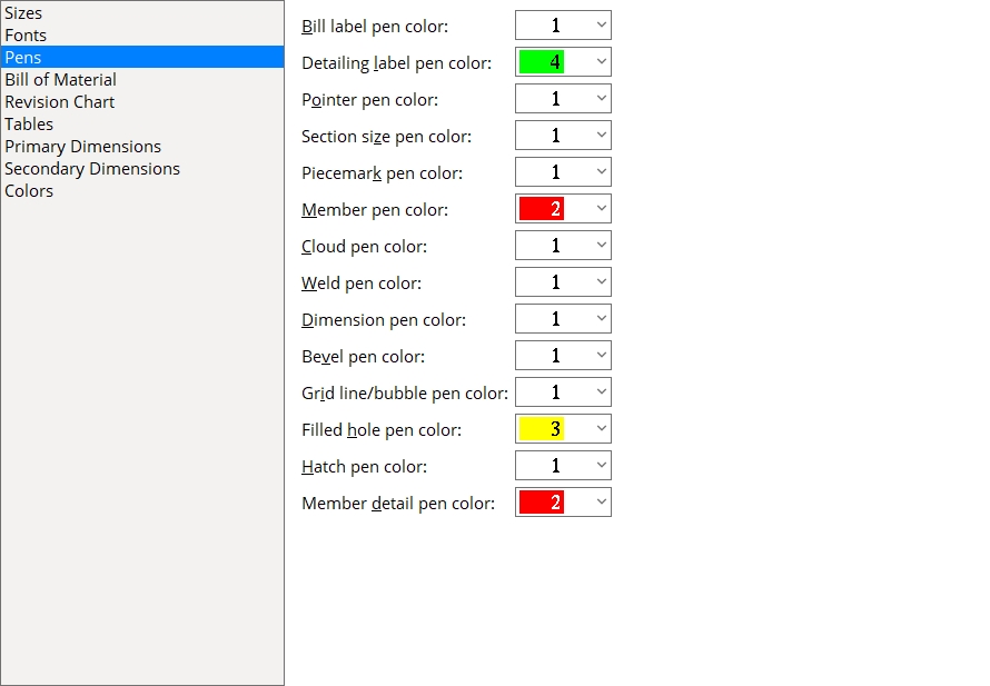
Pens
Note: Line Weights defaults set printers to print detail sheets using black lines of various widths. For example, pen 1 (white), by default, prints a narrow black line. The pens that you select on this screen are applied to drawing objects during automatic detailing.
Bill label pen color: 1 or 2 or 3 or 4 or 5 or 6 or 7. Make the selection you want here before Plotting. Any change you make here will be applied to existing sheets and sheet outlines as well as to sheets that you create in the future. This applies to entries made to a revision chart as well as to a bill of material.
|
| The Bill label pen color applied to the bill of material shown above is 1 (white). This text will appear in a bill when you Sheet Item Add or Detail Sheet Autoload. It will also appear in a revision chart. |
For a TrueType font, this setting affects the display color of that font while you are in the Drawing Editor, but does not in any way affect the plotted appearance of the font.
For the SDS2 font, the pen sets the plotted stroke weight (thickness) of the text that is plotted on line 1 and in other lines in an automatically detailed bill of material. It will also affect the stroke weight of text in a revision chart. This effect will not be seen in the Drawing Editor, but will be evident on the printed drawing.
Also see: The Bill of material font sets the font that is used for information that is compiled into a bill of material.
Detailing label pen color: 1 or 2 or 3 or 4 or 5 or 6 or 7. Make the choice you want here before you Detail Members or Detail Submaterial. Your choice affects the on-screen display color of detailing labels and, if you are using theSDS2 font, it affects the printed thickness (though not the displayed thickness) of that font.
|
For a TrueType font, this option affects the display color of that font while you are in the Drawing Editor, but does not in any way affect the plotted appearance of the font.
For the SDS2 font, the pen sets the plotted stroke weight (thickness) of the text used for labels. You will not see this effect in the Drawing Editor, but you will see it on the printed drawing. If you allow overlapping of dimension lines and labels, you'll probably want to print labels and dimension labels with a thick pen. Line thicknesses for each of the seven drawing pens may be set up using Home > Project Settings > Fabricator > Detailing > Line Weights.
Also see: The Label font sets the font to be used for detailing labels.
Pointer pen color: 1 or 2 or 3 or 4 or 5 or 6 or 7 (see note).
|
Effect on auto detailing: The drawing pen for plotting that is selected here sets the on-screen display color of pointers generated automatically when you Detail Members or Detail Submaterial.
Effect on printing: The selection made here also sets the default line thickness and default color of printed or printed pointers since this sets the default pen number, and it is the pen number of an object that sets its printed thickness and color. To change the line thickness and line color that a particular drawing pen will apply to objects during printing and printing, see Line Weights. Also see the note at the beginning of this section.
Section size pen color: 1 or 2 or 3 or 4 or 5 or 6 or 7 (see note). The choice made here sets the on-screen display color of section sizes in Modeling and on section size labels generated automatically when you Detail Erection Views. If you are using the SDS2 font, this also affects the printed thickness (though not the displayed thickness) of that font.
|
For a TrueType font, this option affects the display color of that font while you are in the Drawing Editor, but does not in any way affect the plotted appearance of the font.
For the SDS2 font, the pen sets the stroke weight (thickness) of the section size text when it is plotted. The stroke weight of the font is not shown in the Drawing Editor, but will only become evident when the drawing is plotted or printed.
Note: In Modeling, section sizes are displayed in the SDS2 font. In the Drawing Editor, the font used for section sizes on erection views is the Member labels font that was selected on this screen at the time that Detail Erection Views was done.
Piecemark pen color: 1 or 2 or 3 or 4 or 5 or 6 or 7 (see note). The choice made here sets the on-screen display color of section sizes in Modeling and on section size labels generated automatically when you Detail Erection Views. If you are using the SDS2 font, this also affects the printed thickness (though not the displayed thickness) of that font.
|
For a TrueType font, this option affects the display color of that font while you are in the Drawing Editor, but does not in any way affect the plotted appearance of the font.
For the SDS2 font, the selected drawing pen sets the stroke weight (thickness) of the piecemark text when it is plotted. The stroke weight of the font as it is shown in the Drawing Editor is always the same, regardless of which drawing pen that is selected.
Note: In Modeling, piecemarks are displayed in the SDS2 font. In the Drawing Editor, the font used for piecemarks on erection views is the Member labels font that was selected on this screen at the time that Detail Erection Views was done.
Member pen color: 1 or 2 or 3 or 4 or 5 or 6 or 7 (see note).
|
Effect on modeling and detailing: The drawing pen that is selected here sets the on-screen display color of members in stick form in Modeling and on erection view drawings that are generated automatically when you Detail Erection Views for the first time, or when you re-detail them and check the box for Reset member line pens.
Effect on printing: When those same erection views drawings have been placed on sheets and printed, the drawing pen number applied to members sets the plotted line thickness and line color of those members. To change the line thickness and line color that a particular drawing pen will apply during printing and printing, see Line Weights. Also see the note at the beginning of this section.
Cloud pen color: 1 or 2 or 3 or 4 or 5 or 6 or 7 (see note).
|
Effect on detailing: The selection made here sets the on-screen display color of clouds generated automatically when you Detail Members or Detail Submaterial. Detailing with templates can, potentially, override the selection made here.
Effect on printing: When a sheet is plotted, the drawing pen that is assigned to objects such as clouds on that sheet sets the printed stroke thickness and color of those objects. To change the stroke thickness and color that a particular drawing pen will apply during printing and printing, see Line Weights. Also see the note at the beginning of this section.
Weld pen color: 1 or 2 or 3 or 4 or 5 or 6 or 7 (see note).
|
A weld symbol that is drawn with pen 1 (white). |
Effect on detailing: The selection made here sets the Pen color that is applied to a weld symbol the first time you Detail Members or any time you subsequently detail and select None for Preserve existing drawing annotations.
Effect on printing, line thickness: During printing, the weld symbol's pen number sets the plotted line thickness of the weld symbol. To change the line thickness that will be applied to graphic objects drawn with a particular drawing pen during printing and printing, see Line Weights. Also see the note at the beginning of this section.
Effect on printing, text: If you are using theSDS2 font, weld symbol's pen number also affects the printed stroke thickness (though not the Drawing Editor's displayed thickness) of that font. For a TrueType font, the pen number does not affect the text's thickness. The font applied to weld symbol tail text during Detail Members is the Symbols font.
User-added weld symbols: For weld symbols drawn using Weld Add or Weld Combo, this is the pen number that is used during a Drawing Editor session until you change weld symbols to a different Pen color,after which time Weld Add or Weld Combo operations will apply that different color.
Dimension pen color: 1 or 2 or 3 or 4 or 5 or 6 or 7 (see note). This applies to dimensions and arc dimensions and angle dimensions.
Effect on detailing: The selection made here sets the Pen color that is applied to dimension lines and legs the first time you Detail Members or any time you subsequently detail and select None for Preserve existing drawing annotations. This also sets the color that is applied to dimension lines and legs on submaterial each time that drawing undergoes Detail Submaterial. On erection drawings, dimensions may be automatically detailed when the box is checked for Annotate erection views and/or when the box is checked for Dimension anchor bolt layout.
Effect on printing: During printing of a dimension shown on a drawing, the pen number applied to that dimension sets the line thickness of that dimension's lines and legs. To change the line color and line thickness that a drawing pen applies to an object during printing, see Line Weights. Also see the note at the beginning of this section.
User-added dimensions: For dimension lines and legs drawn using Add Dimension or Dimension Add Horizontal or Dimension Add Vertical or Dimension Add Arc or Add Extension Dimension, this is the pen number that is used during a Drawing Editor session.
Bevel pen color: 1 or 2 or 3 or 4 or 5 or 6 or 7 (see note).
|
A bevel symbol that is drawn with pen 1 (white). |
Effect on detailing: This sets the Pen color that is applied to a bevel symbol the first time you Detail Members or any time you subsequently detail and select None for Preserve existing drawing annotations.The Bevel pen color also sets the color that is applied to a bevel symbol on a submaterial each time that drawing undergoes Detail Submaterial.
Effect on printing, bevel lines: During printing, the pen number of a bevel symbol sets the plotted line thickness of that bevel symbol. To change the line color and line thickness that the drawing pen applies to a bevel symbol (or other object) during printing, see Line Weights. Also see the note at the beginning of this section.
Effect on printing, bevel text: If you are using the SDS2 font, the pen number also affects the printed thickness of that font (not the displayed thickness in Drawing Editor). For a TrueType font, the selected pen number does not affect the text's thickness. The font applied to bevel symbol text during Detail Members is the Symbols font
User-added bevel symbols: For bevel symbols drawn using Add Bevel Symbol, this is the pen number that is used during a Drawing Editor session until you change one or more bevel symbols to a different Pen color, after which time Add Bevel Symbol operations will apply that different color.
Grid line/bubble pen color: 1 or 2 or 3 or 4 or 5 or 6 or 7. This option sets the default display color for each new grid line that is added in Modeling.
|
|
|
| In Modeling, the choice made here sets the default display color of the grid line and grid bubble (if there is one), but not the color of the text that is the grid line's name. |
For straight grid lines, the choice made here only affects the display color of the grid line. Straight grid lines appear in Modeling only. Straight grid lines cannot be made to appear on erection view drawings. They can be dimensioned on erection view drawings, but do not actually appear as objects on those drawings.
For curved grid lines, the choice made here may also affect the Drawing Editor pen number that is applied to the grid line when an erection view drawing shows the curved grid line. A curved grid line that appears in a Modeling erection view may be generated on that view's drawing if
Annotate erection views is checked when that erection view is detailed. The pen number that is applied to a curved grid line will directly affect the plotted line thickness of that curved grid line when it is plotted. Line Weights sets the thickness of lines drawn for each of the seven pen numbers that can be applied to graphic objects (lines, arcs, etc.) in the Drawing Editor.
Also see: In Modeling, the Grid line pen color lets you change the display color for individual grid lines (straight or curved). Grid lines can be added in Modeling using Add Grid Line or Add Curved Grid, 3 Points or Add Curved Grid, Radius. In the Drawing Editor, curved grid lines on erection view drawings are arcs. You can change the Pen color of these arcs on the Arc Edit window.
Filled hole pen color: 1 or 2 or 3 or 4 or 5 or 6 or 7 (see note). This sets the display color for flat holes in the Drawing Editor. Line Weights defaults set all pen numbers to black. This option does not set the pen number for plotting holes -- it sets their Drawing Editor display color only. Pen 0 is the Line Weights pen for plotting filled holes.
|
Only holes that are shown as flat (in the same plane as the surface they are on) are filled with the Filled hole pen color. |
User-added holes: Holes that are added manually in the Drawing Editor using Hole Add will be filled with this color if they are flat. A user-added flat hole is placed by locating the same point twice. Side views of holes, which are added by locating two different points are not filled.
Holes on erection views that were detailed with the Steel member style set to Wire or Stick + wire are filled with the Filled hole pen color that is selected here.
For member details, Detail Members fills holes that are shown as flat using the Filled hole pen color.
For submaterial details, Detail Submaterial fills holes that are flat using the Filled hole pen color.
Hatch pen color: 1 or 2 or 3 or 4 or 5 or 6 or 7 (see note). This sets the pen (color) that, by default, is selected as the Hatch pen color for the first hatch that is added during a Drawing Editor session. Hatches subsequently added during that same session will, by default, be assigned the Hatch pen color of the last-added hatch.
The choice made to Hatch pen color (in the Drawing Editor) sets the thickness of the lines that make up the hatch pattern. It also sets the hatch's on-screen display color. The actual color of the hatch pattern, when printed, is defined in Line Weights. By default, all drawing pens are defined to be the color black.
|
Same hatch pattern, six different pen numbers. The pen width (mm) for each pen number is written in parentheses. The pen widths are assigned to pen numbers in Line Weights. |
Member detail pen color: 1 or 2 or 3 or 4 or 5 or 6 or 7 (see note).
|
The Member detail pen color applies to submaterial details as well as member details. A submaterial detail is shown in this example. |
Effect on detailing: This sets the default Pen color for polygon sides when you Detail Members or Detail Submaterial.
Effect on printing: During printing of a submaterial or member detail, the pen number sets the line thickness of material polygons that are represented on the drawing. To change the line color and line thickness that a drawing pen applies to an object during printing, see Line Weights. Also see the note at the beginning of this section.
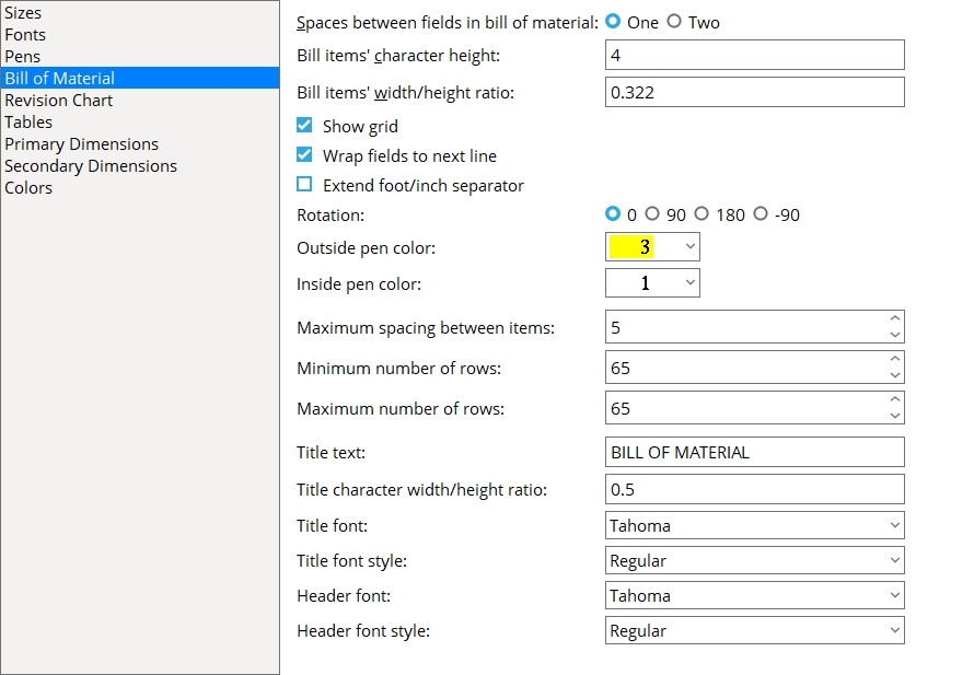
Bill of Material
Make entries to options on this screen before using Place Bill on a sheet outline. Note that two options on the Fonts screen -- Bill of material font and Bill of material font style -- also affect subsequently placed bills of material. For other related setup options, see setup considerations for bill tools.
Spaces between fields in bill of material: One or Two. This affects the space between vertical lines in the bill of material. The choice you make here will be applied to each new bill of material that you create using Place Bill.
If One is selected, then one space will separate columns in a bill of material that has been plotted.
If Two is selected, then two spaces will separate columns on the plotted bill of material.
Bill items' character height: The character height (millimeters) of headers and data listed in the bill of material.
Effect on new bills of material: The character height entered here is applied to the headers of the bill that is created when you use Place Bill to add a new bill of material. This same character height is applied to bill data that is compiled into the bill when you Sheet Item Add. Characters in the bill will be this height when it is plotted. This applies to whatever font is selected as the Bill of material font,regardless of whether that font is a TrueType font or the SDS2 font.
Editing a bill: You can override this setup choice on an individual bill of material by entering a different Character height on the edit window that opens when you double-click that bill.
Bill items' width/height ratio: The width-to-height ratio to be applied to items listed in the bill of material. An entry of .333 designates characters 1/3 as wide as they are tall and is the normal default for letters on a plotted bill of material. This character width is applied to both the headers and the bill data.
|
Effect on new bills of material: The ratio entered here is applied to the headers of the bill that is created when you use Place Bill to add a new bill of material. This same width/height ratio is applied to bill data that is compiled into the bill when you Sheet Item Add. This applies to whatever font is selected as the Bill of material font, regardless of whether that font is a TrueType font or the SDS2 font.
Editing a bill: You can override this setup choice on an individual bill of material by entering a different Bill character width/height ratio on the edit window that opens when you double-click that bill.
Show grid: ![]() or
or ![]() . This applies when you use Place Bill to add a new bill of material.
. This applies when you use Place Bill to add a new bill of material.
|
If this box is checked (
If the box is not checked (
), the bill's interior lines, header text and title text will not be shown.
Editing a bill: After a bill of material has been placed, you can double-click that bill to open that bill's edit window and change the choice made for Show grid.
Wrap fields to next line: ![]() or
or ![]() . This applies when, in the Bill Editor, more characters have been entered to a cell than that cell has room for. The text wrapping will become evident when you use Place Bill to add a new bill of material or when you use Sheet Item Add to add bill data to a bill of material.
. This applies when, in the Bill Editor, more characters have been entered to a cell than that cell has room for. The text wrapping will become evident when you use Place Bill to add a new bill of material or when you use Sheet Item Add to add bill data to a bill of material.
|
|||||
| In this example, too much text (shown in green) was added to the Remarks column for a particular piece of material. |
If this box is checked (
If the box is not checked (
Editing a bill: On a bill of material that has been placed, you can double-click that bill to open the bill's edit window and change the choice made for Wrap to next line.
Extend foot/inch separator: ![]() or
or ![]() . This applies when a Length column is included in the bill of material and the primary dimension Units is set to Imperial (feet-in frac). This sets the default choice made for Extend foot/inch separator that will be applied when you Place Bill.
. This applies when a Length column is included in the bill of material and the primary dimension Units is set to Imperial (feet-in frac). This sets the default choice made for Extend foot/inch separator that will be applied when you Place Bill.
|
|||||
| To see the difference, look at the second row of the Length column. |
If this box is checked (
If the box is not checked (
Editing a bill: On a bill of material that has been placed, you can double-click that bill to open the bill's edit window and change the choice made for Extend foot/inch separator.
Rotation: 0º or 90º or 180º or -90º. Rotation is counterclockwise around what, for a 0 degree rotation, would be the upper, right corner of the bill. This sets the default Rotation that will be applied when you Place Bill.
|
Editing a bill: The Rotation of an individual bill of material can be changed on the edit window for that bill.
Outside pen color: 1 or 2 or 3 or 4 or 5 or 6 or 7. This sets the default Outside pen color that will be applied when you Place Bill to add a new bill of material.
|
|
| The selected button sets the drawing pen and on-screen display color of the bill of material's perimeter. Line Weights sets the thickness of lines that are printed using a particular drawing pen. |
|
The outside pen color sets the display color and plotted line thickness of the bill's perimeter. In this example, the color is yellow (pen 3). |
Editing a bill: You can enter a different Outside pen color on the edit window that opens when you double-click that bill.
Inside pen color: 1 or 2 or 3 or 4 or 5 or 6 or 7. This sets the default Inside pen color that will be applied when you Place Bill to add a new bill of material.
|
|
| The selected button sets the drawing pen and on-screen display color of the bill of material's interior grid of lines. Line Weights sets the printing thickness of printed lines for each of the seven drawing pens. |
|
|
The inside pen color sets the display color and the plotted line thickness for the bill's inner grid. In this example, the color is white (pen 1). |
Editing a bill: The Inside pen color of an individual bill of material can be changed on that bill's Bill of Material Layout window. Just double-click the bill.
Maximum spacing between items: A number of blank rows. This applies when bill data for more than one member is included in a bill of material. If there isn't enough room to apply the maximum number of blank rows, the number of blank rows may be reduced to as few as one row. The number entered here sets the default Maximum spacing between items that will be applied to new bills of material subsequently placed using Place Bill.
|
s = spacing. In this example, the spacing is two rows. The two rows separate the bill data for member B_11 from the bill data for member B_12. |
Editing a bill: The Maximum spacing between items can be changed on the edit window for an individual bill of material.
Minimum number of rows: The number of rows that will be shown when the bill of material has no bill data compiled into it. When you Sheet Item Add and thus increase the amount of bill data compiled into the bill, the number of lines will increase beyond this minimum if doing so is required to accommodate the added data and if the Maximum number of rows is set to a larger number than the minimum.
|
In this example, the headers take up 2 rows, the bill data takes up 5 rows, and the Minimum number of rows is 10. This leaves 3 blank rows. |
Editing a bill: Once that bill is placed using Place Bill, it's Minimum number of rows can be changed on the window that opens when you double-click that bill of material.
Maximum number of rows: The number of rows that a bill of material is allowed to dynamically expand to in order to accommodate new bill data that is added when you Sheet Item Add. This sets the default Maximum number of rows that will be applied to new bills of material subsequently placed using Place Bill.
|
In this example, the bill data spills out past the bottom edge of the bill. To fix this problem, you could double-click the bill of material then increase the Maximum number of rows on that bill of material's edit window. |
Title text: The characters in the bill of material's title. Up to 61 characters may be entered. This sets the default Title text that will be applied to new bills of material subsequently placed using Place Bill.
|
The Title text in this example is LISTADO DE MATERIALES.Keep your title short. If you enter too many characters, your title will run outside the bounds of the bill. |
Editing a bill: You can change a placed bill's Title text on the edit window that opens when you double-click that bill of material.
Title character width/height ratio: The width/height of the characters that make up the title text in the bill of material. This sets the default Title character width/height ratio that will be applied to new bills of material subsequently placed using Place Bill.
|
Font dependencies: This applies to whatever font is selected as the Title font, regardless of whether that font is a TrueType font or the SDS2 font. For a TrueType font, a ratio of 0.6 renders that font at its native width. A ratio larger than 0.6 stretches the font. A ratio less than 0.6 compacts the font. For the SDS2 font, 0.4 is the default choice.
Editing a bill: For a bill of material that has already been placed, you can change its Title character width/height ratio on the edit window that opens when you double-click that bill of material.
Title font: Any font that is listed can be selected. The font that is selected applies to the title text, not to the header text or bill data text. This sets the default Title font that will be applied to new bills of material subsequently placed using Place Bill.
|
The Title font applies to the bill title (BILL OF MATERIAL). |
Be sure to also choose the Title font style that you want.
Editing a bill: The Title font can be changed on the edit window for an individual bill of material.
Title font style: The style (Bold or Bold Italic or Italic or Regular) of the selected Title font. Different fonts may have different styles available to them. This sets the default Title font style that will be applied to new bills of material subsequently placed using Place Bill.
Available font styles are listed alphabetically in the font style list box, and the first style that is listed when you change to a different Title font is automatically selected as the style for that font. Instead of using the automatically selected font style you may prefer to choose Regular, which is generally the most popular style for a particular font. Regular is the only choice that is available for the SDS2 font.
Editing a bill: You can change a placed bill's Title font style on the edit window that opens when you double-click that bill of material.
Header font: Any font that is listed can be selected. The font that is selected applies to bill of material headers, not to the bill title or bill data text. This sets the default Header font that will be applied to new bills of material subsequently placed using Place Bill.
|
Headers in this example of a bill of material are displayed in the color red (LINE #, PC MARK, Description, etc.) |
Be sure to also choose the Header font style that you want.
Bill of material headers are named in Home > Project Settings > Fabricator > Sheets and Reports > Bill of Material Layout when users make entries to the Header line 1 and Header line 2 columns on that setup screen. The Header font is applied to headers when a bill of material is created in the Drawing Editor using Place Bill. Typically, bills of material are placed on sheet outlines.
Editing a bill: The Header font can be changed on the edit window for an individual bill of material.
Header font style: The style (Bold or Bold Italic or Italic or Regular) of the selected Header font. Different fonts may have different styles available to them. This sets the default Header font style that will be applied to new bills of material subsequently placed using Place Bill.
Editing a bill: The Header font style can be changed on the edit window for an individual bill of material.
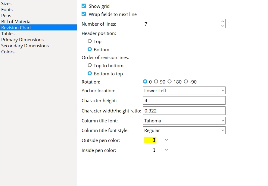
Revision Chart
Additional setup options related to revision charts can be found in Home > Project Settings > Fabricator > Sheets and Reports > Sheet Revisions. Also see Sheet revision font on the Fonts screen.
Show grid: ![]() or
or ![]() . This affects the appearance of a revision chart that is placed onto a sheet or sheet outline using Place Revision Chart in the Drawing Editor.
. This affects the appearance of a revision chart that is placed onto a sheet or sheet outline using Place Revision Chart in the Drawing Editor.
|
If this box is checked (
If the box is not checked (
After a revision chart has been placed, you can use Show grid in the Drawing Editor to override the setup choice made here.
Wrap fields to next line: ![]() or
or ![]() . This sets the default choice made in the Drawing Editor to Wrap fields to next line when you Place Revision Chart a revision chart onto a sheet or sheet outline. The choice made in the Drawing Editor to Wrap fields to next line applies when a revision chart has more characters entered to a cell than that cell has room for.
. This sets the default choice made in the Drawing Editor to Wrap fields to next line when you Place Revision Chart a revision chart onto a sheet or sheet outline. The choice made in the Drawing Editor to Wrap fields to next line applies when a revision chart has more characters entered to a cell than that cell has room for.
|
|||||
| In both of these examples, the revision 2 Description is too long to fit in a single cell. |
If this box is checked (
If the box is not checked (
Note: Entries to a revision chart can be made in the Sheet Revision Chart Editor or automatically during auto detailing.
Number of lines: The number of lines (rows) that will be shown when the revision chart is first placed onto a sheet or sheet outline using Place Revision Chart in the Drawing Editor.
|
The number of lines in this revision chart is 6. |
Overriding the choice made here: If the number of lines entered to the Sheet Revision Chart Editor is greater than the available number of lines in the revisions chart, new lines will automatically be added to the revision chart so that it can accommodate the new information. Also, you can change the Number of lines on the edit window for an individual revision chart.
Header position:
![]() Top or
Top or ![]() Bottom. This sets the default choice made in the Drawing Editor to Header post ion when you Place Revision Chart a revision chart onto a sheet or sheet outline.
Bottom. This sets the default choice made in the Drawing Editor to Header post ion when you Place Revision Chart a revision chart onto a sheet or sheet outline.
|
For this example, Header position is set to Top. Order of revision lines is set to Bottom to top. |
|
For this example, Header position is set to Bottom. Order of revision lines is set to Bottom to top. |
Top when selected for an individual Drawing Editor revision chart places the Header Line for that chart in cells at the top of the revision chart.
What is top? When the revision chart's Rotation is set to 0, the top of a revision chart is the actual top of the revision chart.
Order of revision lines: ![]() Top to bottom or
Top to bottom or ![]() Bottom to top. This sets the default choice made in the Drawing Editor to Order of revision lines when you use Place Revision Chart on a sheet or sheet outline.
Bottom to top. This sets the default choice made in the Drawing Editor to Order of revision lines when you use Place Revision Chart on a sheet or sheet outline.
|
For this example, Order of revision lines is set to Top to bottom. Header position is set to Top. |
|
|
For this example, Order of revision lines is set to Bottom to top. Header position is set to Top. |
What is top? When the revision chart's Rotation is set to 0, the top of a revision chart is the actual top of the revision chart.
Rotation: 0º or 90º or 180º or -90º. Rotation is counterclockwise around the Anchor location of the revision chart. This affects the appearance of a revision chart that is placed onto a sheet or sheet outline using Place Revision Chart in the Drawing Editor.
|
||||||||||||
After a revision chart has been placed, Rotation can be changed on the edit window for an individual revision chart.
Anchor location: Upper left or Upper right or Lower left or Lower right. This sets the location of the insertion point used for Place Revision Chart in the Drawing Editor.
|
| How an insertion point used for Place Revision Chart relates to the revision chart's anchor location. |
Upper left sets the insertion point that is used for Place Revision Chart at the revision chart's upper, left corner.
Upper right sets the insertion point that is used for Place Revision Chart at the revision chart's upper, right corner.
Lower left sets the insertion point that is used for Place Revision Chart at the revision chart's lower, left corner.
Lower right sets the insertion point that is used for Place Revision Chart at the revision chart's lower, right corner.
After a revision chart has been placed, the Anchor location of that already placed revision chart can be changed.
Character height: The character height (millimeters) of all text in any revision chart that is subsequently placed onto a sheet or sheet outline using Place Revision Chart in the Drawing Editor. This applies to both the revision line text (Sheet revision font) and the column title text (Column title font).
|
Line 2 is revision line text. Line 1 is the column title text. |
Font dependencies: This applies to whatever fonts are selected as the Column title font and the Sheet revision font, regardless of whether those fonts are TrueType fonts or the SDS2 font.
After a revision chart has been placed, the Character height can be changed on the edit window for an individual revision chart.
Character width/height ratio: The width/height of the characters that make up the text in revision charts that are subsequently placed using Place Revision Chart in the Drawing Editor. This applies to both the revision line text (Sheet revision font) and the column title text (Column title font).
|
|
Line 2 is revision line text. Line 1 is the column title text. |
Font dependencies: This applies to whatever fonts are selected as the Column title font and the Sheet revision font, regardless of whether those fonts are TrueType fonts or the SDS2 font. For a TrueType font, a ratio of 0.6 renders that font at its native width. A ratio larger than 0.6 stretches the font. A ratio less than 0.6 compacts the font. For the SDS2 font, use the ratio that you think looks best -- 0.4 is the default.
After a revision chart has been placed, the Character width/height ratio can be changed on the edit window for an individual revision chart.
Column title font: Any font that is listed can be selected. The font that is selected applies to the column title text, not to revision line text. This sets the default Column title font that will be applied to new revision charts subsequently placed using Place Revision Chart.
|
Line 1 is the column title text, to which the Column title font applies. |
Be sure to also choose the Column title font style that you want.
After a revision chart has been placed, the Column title font can be changed on the edit window for an individual revision chart.
Column title font style: The style (Bold or Bold Italic or Italic or Regular) of the selected Column title font. Different fonts may have different styles available to them. This sets the default Column title font style that will be applied to new revision charts subsequently placed using Place Revision Chart in the Drawing Editor.
|
|
Line 1 is the column title text, to which the Column title font style applies. |
Available font styles are listed alphabetically in the font style list box, and the first style that is listed when you change to a different Column title font is automatically selected as the style for that font. Instead of using the automatically selected font style you may prefer to choose Regular, which is generally the most popular style for a particular font. Regular is the only choice that is available for the SDS2 font. To adjust the stroke thickness of the SDS2 font, you can change the Bill label pen color on the Pens screen.
After a revision chart has been placed, the Column title font style can be changed on the edit window that opens when you double-click that revision chart.
Outside pen color: 1 or 2 or 3 or 4 or 5 or 6 or 7. This sets the Outside pen color that will be applied whenPlace Revision Chart is used to add a new revision chart.
|
|
| The selected button sets the drawing pen and on-screen display color of the revision chart's perimeter. Line Weights sets the thickness of lines that are printed using a particular drawing pen. |
|
The Outside pen color sets the color and line thickness of the revision chart's perimeter. In this example, the color is yellow (pen 3). |
After a revision chart has been placed, the Outside pen color can be changed on the edit window that opens when you double-click that revision chart.
Inside pen color: 1 or 2 or 3 or 4 or 5 or 6 or 7. This sets the Inside pen color that will be applied when Place Revision Chart is used to add a new revision chart.
|
|
| The selected button sets the drawing pen and on-screen display color of the revision chart's perimeter. Line Weights sets the thickness of lines that are printed using a particular drawing pen. |
|
|
The Inside pen color sets the color and the line thickness for the revision chart's inner grid. In this example, the color is white (pen 1). |
After a revision chart has been placed, the Inside pen color can be changed on the edit window that opens when you double-click that revision chart.
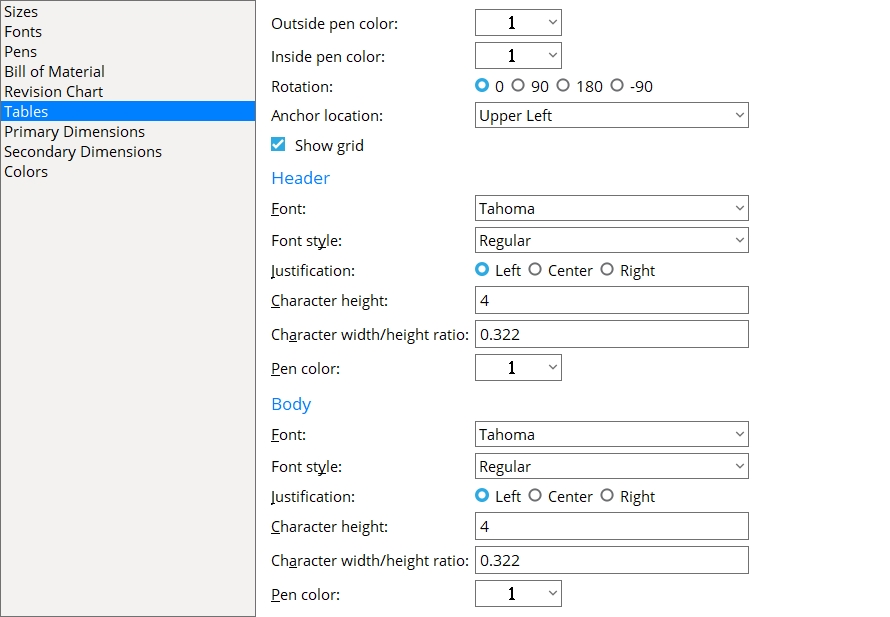
Tables
Outside pen color: 1 or 2 or 3 or 4 or 5 or 6 or 7. When a new table is placed in the Drawing Editor using Table Add, this sets the default pen that is selected for Outside pen color on the Table Edit window.
|
|
| The selected pen sets the on-screen display color of the table's perimeter. Line Weights sets the thickness of lines drawn with that pen. |
|
The Outside pen color sets the color and line thickness of the table's perimeter. In this example, the color is yellow (pen number 3). |
Inside pen color: 1 or 2 or 3 or 4 or 5 or 6 or 7. When a new table is placed in the Drawing Editor using Table Add, this sets the default pen that is selected for Inside pen color on the Table Edit window.
|
|
| The selected pen sets the on-screen display color of the table's interior grid of lines. Line Weights sets the thickness of lines drawn with that pen. |
|
|
The Inside pen color sets the color and line thickness of the table's inner grid. In this example, the color is white (pen number 1). |
Rotation: 0º or 90º or 180º or -90º. When a new table is placed in the Drawing Editor using Table Add, this sets the default choice that is made to Rotation on the Table Edit window.
|
Rotation is counterclockwise around the Anchor location. For the above examples, the Anchor location is set to Upper left.
Anchor location: Upper left or Upper right or Lower left or Lower right. When a new table is placed in the Drawing Editor using Table Add, this sets the default choice that is made to Anchor location on the Table Edit window. The Anchor location sets the insertion point for the table. Since the Table Edit window opens before a table is located during an Table Add operation, the default choice made here can be changed in the Drawing Editor prior to adding the table.
|
|
Upper left is the upper, left corner of the table when the Rotation is set to 0º.
Upper right is the upper, right corner of the table when the Rotation is set to 0º.
Lower left is the lower, left corner of the table when the Rotation is set to 0º.
Lower right is the lower, right corner of the table when the Rotation is set to 0º.
Show grid: ![]() or
or ![]() . When a new table is placed in the Drawing Editor using Table Add, this sets the default choice that is made to Show grid on the Table Edit window.
. When a new table is placed in the Drawing Editor using Table Add, this sets the default choice that is made to Show grid on the Table Edit window.
|
If this box is checked (
If the box is not checked (
Header
Font: Any font that is listed can be selected for the header text. When a new table is placed in the Drawing Editor using Table Add, this sets the default choice that is made to the header Font on the Table Edit window.
|
For a TrueType font, such as any of those shown here, set the header-text Character width/height ratio to 0.6 to have the font rendered at its native width. |
Be sure to also choose the header-text Font style that you want. The header-text Character height sets the font size. If you select the SDS2 font, be aware that the header-text Pen color affects the thickness of the font when it is plotted.
Font style: The style (Bold or Bold Italic or Italic or Regular) of the selected header-text Font. When a new table is placed in the Drawing Editor using Table Add, this sets the default choice that is made to the header Font style on the Table Edit window.
Available font styles are listed alphabetically in the font style list box, and the first style that is listed for a particular font is the style that is selected by default. You may, instead of using the default, prefer to choose Regular, which is generally the most popular style for a particular font. Regular is the only choice that is available for the SDS2 font. To adjust the stroke thickness of the SDS2 font, you can change the header-text Pen color.
Justification: Left or Center or Right. When a new table is placed in the Drawing Editor using Table Add, this sets the default choice that is made to the header Justification on the Table Edit window.
|

Left left-justifies the header text in each of the header cells.
Center centers the header text in each of the header cells.
Right right-justifies the header text in each of the header cells.
Character height: The height (millimeters) of letters/numbers that make up the header text. When a new table is placed in the Drawing Editor using Table Add, this sets the default choice that is made to the header Character height on the Table Edit window.
|
Font dependencies: This applies to whatever font is selected as the header-text Font, regardless of whether that font is a TrueType font or the SDS2 font.
Character width/height ratio: The width/height of the characters that make up the label. When a new table is placed in the Drawing Editor using Table Add, this sets the default choice that is made to the header Character width/height ratio on the Table Edit window.
|
Tip: Set this to 0.6 for a TrueType font. For the SDS2 font, 0.4 is a good choice.
Pen color: 1 or 2 or 3 or 4 or 5 or 6 or 7. When a new table is placed in the Drawing Editor using Table Add, this sets the default choice that is made to the header Pen color on the Table Edit window.
|
|
For a TrueType header-text font, the Pen color affects the display color of the header text while you are in the Drawing Editor, but does not affect the plotted appearance of the Font so long as all pens in Line Weights are set to print in black. By default, all pens in Line Weights are set to print in black.
For the SDS2 Font, the pen color sets the stroke weight (thickness) of the label characters. Line Weights assigns a particular thickness to each Pen color.
Body
Font: Any font that is listed can be selected When a new table is placed in the Drawing Editor using Table Add, this sets the default choice that is made to the body-text Font on the Table Edit window.
|
For a TrueType font, such as any of those shown here, set the body-text Character width/height ratio to 0.6 to have the font rendered at its native width. |
Be sure to also choose the body-text Font style that you want. The body-text Character height sets the font size. If you select the SDS2 font, be aware that the body-text Pen color affects the thickness of the font when it is plotted.
Font style: The style (Bold or Bold Italic or Italic or Regular) of the selected body-text Font. When a new table is placed in the Drawing Editor using Table Add, this sets the default choice that is made to the body-text Font style on the Table Edit window.
Available font styles are listed alphabetically in the font style list box, and the first style that is listed for a particular font is the style that is selected by default. You may, instead of using the default, prefer to choose Regular, which is generally the most popular style for a particular font. Regular is the only choice that is available for the SDS2 font. To adjust the stroke thickness of the SDS2 font, you can change the body-text Pen color.
Justification: Left or Center or Right. When a new table is placed in the Drawing Editor using Table Add, this sets the default choice that is made to the body-text Justification on the Table Edit window.
|
Left left-justifies the text in each of the body cells.
Center centers the text in each of the body cells.
Right right-justifies the text in each of the body cells.
Character height: The height (millimeters) of letters/numbers that make up the body text. When a new table is placed in the Drawing Editor using Table Add, this sets the default choice that is made to the body-text Character height on the Table Edit window.
|
Font dependencies: This applies to whatever font is selected as the body-text Font, regardless of whether that font is a TrueType font or the SDS2 font.
Character width/height ratio: The width/height of the characters that make up the body text. When a new table is placed in the Drawing Editor using Table Add, this sets the default choice that is made to the body-text Character width-height ratio on the Table Edit window.
|
Tip: Set this to 0.6 for a TrueType font. For the SDS2 font, 0.4 is a good choice.
Pen color: 1 or 2 or 3 or 4 or 5 or 6 or 7. When a new table is placed in the Drawing Editor using Table Add, this sets the default choice that is made to the body-text Pen color on the Table Edit window.
|
|
For a TrueType body-text font, the Pen color affects the display color of the body text while you are in the Drawing Editor, but does not affect the plotted appearance of the Font so long as all pens in Line Weights are set to print in black. By default, all pens in Line Weights are set to print in black.
For the SDS2 Font, the pen color sets the stroke weight (thickness) of the label characters. Line Weights assigns a particular thickness to each Pen color.
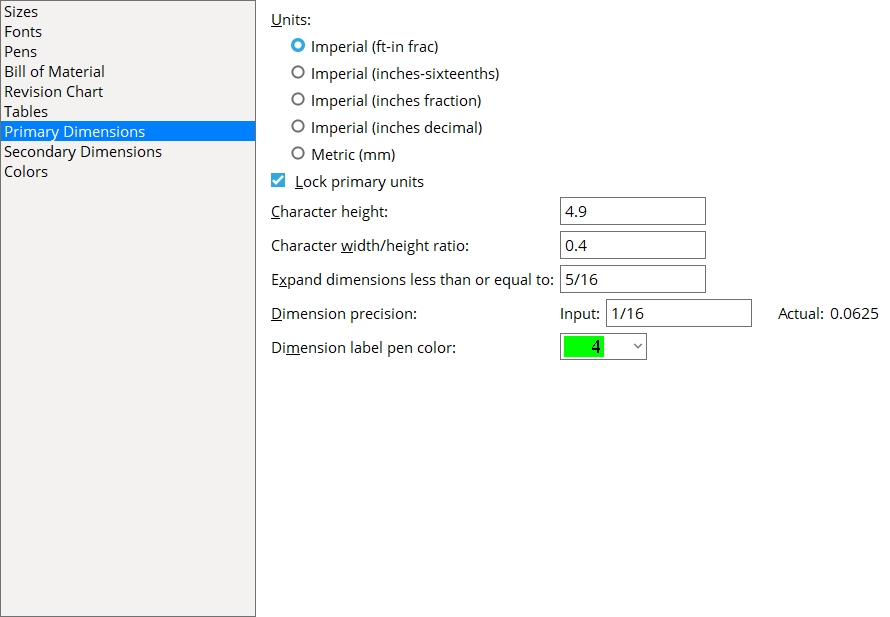
Primary Dimension
|
Units: Imperial (feet-in frac) or Imperial (inches-sixteenths) or Imperial (inches fraction) or Imperial (inches decimal) or Metric (mm). The selection made here affects Process and Create Solids and auto detailing (see note 2). It also sets the units that you must use when entering distances. On details with dual dimensioning, the choice made here sets the primary dimension units (see Display secondary dimensions).
|
|
Imperial (ft-in frac) expresses distance measurements throughout your current Job in feet and inches. You may then enter dimensions using a dash (e.g., 10-0 means ten feet, six inches) and by placing a space between inches and fractions of an inch (e.g., 2 1/2 signifies two-and-a-half inches). Weights of materials are in pounds; loads are in kips; tonnages are in tons (2,000 lbs). Also see note 1.
Imperial (inches-sixteenths) sets distance measurements to be expressed in inches and fractions of an inch with a dash separating the units (e.g., two feet and one-half inch is 24-8). See entering distances. Weights of materials are in pounds; loads are in kips. Tonnages are in tons (2,000 lbs). Also see note 1.
Imperial (inches fraction) sets distance measurements to be expressed in inches and fractions of an inch (e.g., two feet and one-half inch is 24 1/2). Weights of materials are in pounds; loads are in kips; tonnages are in tons (2,000 lbs).
Imperial (inches decimals) sets distance measurements to be expressed in decimal inches (e.g., two feet and one-half inch is 24.5). Weights of materials are in pounds; loads are in kips; tonnages are in US tons (2,000 lbs).
Metric expresses distance measurements in millimeters. You cannot use dashes to write metric distances. Metric weights of materials are in kilograms; loads are in kilonewtons; tonnages are in metric tons (1,000 kg). If you enter fractions, the units are interpreted as being inches (in).
Note 1: If the units are not shown in a dimension field, the reported distance is in the primary dimension Units that are set here. That reported distance is a multiple of the Dimension precision. Units other than the primary dimension units may be shown in a dimension field when
Note 2: If you change the Dimension units in the middle of a job and want all details output with the same units, all to-be-detailed members should first undergo Process & Create Solids. If you changed Dimension units in order to output a few details in different units, only automatic detailing is required. See entering distances.
In the following example, the Units are Imperial (ft-in frac), and the entered value and stored value are the same in each case. The displayed value changes when Lock... is turned on or off.
Entered value: 
Stored value: 
Displayed value: 
If this box is checked (
If this box is not checked (
Character height: The character height (millimeters) of the primary dimension label (upper label on a dual dimension, only label on a mono dimension). This value is independent of the Drawing scale of a drawing. Assuming that the sheet a drawing is placed on has a scale of 1:1 and you do not re-scale the labels and the printer does not adjust the scale, this will be the actual height of characters on the plotted sheet.
|
Effect on detailing: The character height entered here applies to details whose piecemarks you select when you Detail Members or Detail Submaterial. Your entry also becomes the default for dimensions added using Add Dimension.
Font dependencies: This applies to whatever font is selected as the Dimension label font, regardless of whether that font is a TrueType font or the SDS2 font.
Character width/height ratio: The width/height ratio of characters of the primary dimension label (upper label on a dual dimension, only label on a mono dimension).
|
Effect on detailing: The ratio entered here applies to details whose piecemarks you select when you Detail Members or Detail Submaterial. It will also becomes the default for dimension labels added using Add Dimension or related tools.
Font dependencies: This applies to whatever font is selected as the Dimension label font, regardless of whether that font is a TrueType font or the SDS2 font. For a TrueType font, a ratio of 0.6 renders that font at its native width. A ratio larger than 0.6 stretches the font. A ratio less than 0.6 compacts the font. For the SDS2 font, a ratio of 0.4 produces attractive results.
Expand dimensions less than or equal to: Any distance (0 to 1 inch imperial; 0 to 25 mm metric). The entry made here applies to details whose piecemarks you select when you Detail Members or Detail Submaterial. It also applies to dimensions added using Add Dimension.
|
0 (zero) results in dimensions not being expanded.
The entry of a distance greater than zero causes dimensions of that distance or smaller to be expanded if expanding does not interfere with reading of the drawing.
Dimension precision: The precision (to 1/32 inch imperial; to 0.1 mm metric) that you want applied to dimensions reported on drawings and in the bill of material.
Tip: If you are using both Imperial... and Metric Units,you should set the Dimension precision for both units.
|
|||||
This does not affect Bolt diameter or the Material thickness of a rectangular plate, round plate, bent plate, rolled plate, flat plate layout, bent plate layout and flat bar. Also, a plate may be the specified gage (GA), regardless of the dimension precision.
For materials other than plates and bolts, the Dimension precision entered here does affect the material Length, Width, and Thickness reported in the bill of material.
Dimension precision also applies to the details of members or submaterials whose piecemarks you select when you Detail Members or Detail Submaterial. And it applies to dimensions added using Add Dimension.
The precision of entries that you can make when entering distances to member and material edit window fields are directly affected by the entry made here. Dimensions that are not within this precision are rounded up as you make entries into the Length, Width, Thickness and other dimension fields on edit windows.
Dimension precision also affects how you make entries in units other than the Units that your current Job is set for. For example, when you enter millimeters in an Imperial... Job, the number of units that you enter must be a multiple of the Dimension precision set for those other units in that Job. For example, you cannot enter .3mm to a dimension field in an Imperial Job if the Dimension precision is set to 1 mm -- you would have to first set the Units to Metric, change the Dimension precision to .1 mm then change the Units back to Imperial....
If Round flat plate values is checked in Plate Design Settings, the precision entered here may affect Create Solids. Entering a value larger than 1/16 inch (1.6 mm) may cause your bill of material to call out connection materials that are thicker and/or wider and/or longer than design routines calculate they should be.
Dimension label pen color: 1 or 2 or 3 or 4 or 5 or 6 or 7 (see note). The dimension label is the label (usually specifying a distance) which appears on a dimension.
|
Effect on detailing: The drawing pen selected here applies to dimension and arc dimension labels drawn using Add Dimension or Dimension Add Arc as well as dimension labels drawn automatically when you Detail Members or Detail Submaterial.
For a TrueType font, this option affects the display color of that font while you are in the Drawing Editor, but does not in any way affect the plotted appearance of the font.
For the SDS2 font, the pen number sets the stroke weight (thickness) of the dimension label text when it is plotted. The stroke weight of the font as it is shown in the Drawing Editor is not affected by the pen.
Tip: If you allow overlapping of dimension lines and labels, you'll probably want to print labels and dimension labels with a wide pen. A distinct line thickness may be set up for each of the seven drawing pens using Home > Project Settings > Fabricator > Detailing > Line Weights.
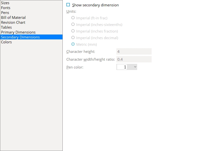
Secondary Dimension
|
Show secondary dimensions: ![]() or
or ![]() . This applies to dimensions drawn interactively using Add Dimension or related tools as well as dimensions drawn automatically when you Detail Members or Detail Submaterial.
. This applies to dimensions drawn interactively using Add Dimension or related tools as well as dimensions drawn automatically when you Detail Members or Detail Submaterial.
|
|||
| The primary dimension is placed above the dimension line. The secondary dimension is placed below it. |
If this box is checked (
If the box is not checked (
Units: Same as the primary dimension Units, except that this applies to secondary dimension labels.
Tip: If you selected imperial dimensioning as the primary dimension Units, you may want to select Metric here. If you selected Metric as the primary dimension Units,you may want to select Imperial (feet-in frac) here.
Character height: Same as the primary dimension Character height, except that this applies to secondary dimension labels.
Character width/height ratio: Same as the primary dimension Character width/height ratio, except that this applies to secondary dimension labels.
Pen color: Same as the primary dimension Dimension label pen color, except that this applies to secondary dimension labels.
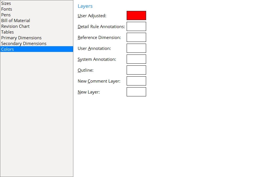
Colors
User Adjusted: The color that you want applied to objects that appear on the User Adjusted layer of a drawing. A color is specified by clicking the Pick swatch and defining a color using your operating system's color picker. The color picked here is assigned to each User Adjusted layer during auto detailing and can be changed -- for individual drawings -- on the Layer Panel in Drawing Editor. If User and Site Options > Drawings > ![]() Show layer colors in Drawing Editor is checked, the color specified here can potentially be used to identify graphic objects that are on the User Adjusted layer on a member detail, submaterial detail or erection view drawing. If User and Site Options > Output >
Show layer colors in Drawing Editor is checked, the color specified here can potentially be used to identify graphic objects that are on the User Adjusted layer on a member detail, submaterial detail or erection view drawing. If User and Site Options > Output > ![]() Show layer colors on PDFs is checked, the color specified here can potentially be used to identify those same graphic objects on PDF drawings of members, submaterials and erection views.
Show layer colors on PDFs is checked, the color specified here can potentially be used to identify those same graphic objects on PDF drawings of members, submaterials and erection views.
Detail Rule Annotations: The color that you want applied to objects that appear on the Detail Rule Annotations layer of a drawing.
Reference Dimension: The color that you want applied to objects that appear on the Reference Dimension layer of a drawing. A color is specified by clicking the Pick swatch and defining a color using your operating system's color picker. The color picked here is assigned to each Reference Dimension layer during auto detailing and can be changed -- for individual drawings -- on the Layer Panel in Drawing Editor. If User and Site Options > Drawings > ![]() Show layer colors in Drawing Editor is checked, the color specified here can potentially be used to identify dimensions that are on the Reference Dimension layer on a member detail, submaterial detail or erection view drawing. If
Show layer colors in Drawing Editor is checked, the color specified here can potentially be used to identify dimensions that are on the Reference Dimension layer on a member detail, submaterial detail or erection view drawing. If ![]() Show layer colors on PDFs is checked, the color specified here can potentially be used to identify those same dimensions on PDF drawings of members, submaterials and erection views.
Show layer colors on PDFs is checked, the color specified here can potentially be used to identify those same dimensions on PDF drawings of members, submaterials and erection views.
User Annotation: The color that you want applied to objects that appear on the User Annotation layer of a drawing. A color is specified by clicking the Pick swatch and defining a color using your operating system's color picker. The color picked here is assigned to each User Annotation layer during auto detailing and can be changed -- for individual drawings -- on the Layer Panel in Drawing Editor. If User and Site Options > Drawings > ![]() Show layer colors in Drawing Editor is checked, the color specified here can potentially be used to identify annotations that are on the User Annotation layer on a member detail, submaterial detail or erection view drawing. If User and Site Options > Output >
Show layer colors in Drawing Editor is checked, the color specified here can potentially be used to identify annotations that are on the User Annotation layer on a member detail, submaterial detail or erection view drawing. If User and Site Options > Output > ![]() Show layer colors on PDFs is checked, the color specified here can be used to identify those same annotations on PDF drawings of members, submaterials and erection views.
Show layer colors on PDFs is checked, the color specified here can be used to identify those same annotations on PDF drawings of members, submaterials and erection views.
System Annotation: The color that you want applied to objects that appear on the System Annotation layer of a drawing. A color is specified by clicking the Pick swatch and defining a color using your operating system's color picker. The color picked here is assigned to each User Annotation layer during auto detailing and can be changed -- for individual drawings -- on the Layer Panel in Drawing Editor. If User and Site Options > Drawings > ![]() Show layer colors in Drawing Editor is checked, the color specified here can potentially be used to identify annotations that are on the System Annotation layer on a member detail, submaterial detail or erection view drawing. If User and Site Options > Output >
Show layer colors in Drawing Editor is checked, the color specified here can potentially be used to identify annotations that are on the System Annotation layer on a member detail, submaterial detail or erection view drawing. If User and Site Options > Output > ![]() Show layer colors on PDFs is checked, the color specified here can potentially be used to identify those same annotations on PDF drawings of members, submaterials and erection views.
Show layer colors on PDFs is checked, the color specified here can potentially be used to identify those same annotations on PDF drawings of members, submaterials and erection views.
Outline: The color that you want applied to objects that appear on the Outline Annotation layer of a drawing. A color is specified by clicking the Pick swatch and defining a color using your operating system's color picker. The color picked here is assigned to each Outline layer during auto detailing and can be changed -- for individual drawings -- on the Layer Panel in Drawing Editor. If User and Site Options > Drawings > ![]() Show layer colors in Drawing Editor is checked, the color specified here can potentially be used to identify material polygons that are on the Outline layer on a member detail, submaterial detail or erection view drawing. If User and Site Options > Output >
Show layer colors in Drawing Editor is checked, the color specified here can potentially be used to identify material polygons that are on the Outline layer on a member detail, submaterial detail or erection view drawing. If User and Site Options > Output > ![]() Show layer colors on PDFs is checked, the color specified here can potentially be used to identify those same material polygons on PDF drawings of members, submaterials and erection views.
Show layer colors on PDFs is checked, the color specified here can potentially be used to identify those same material polygons on PDF drawings of members, submaterials and erection views.
New Comment Layer: The color that you want applied to objects that appear on each new comment layer that is created manually by users, while in any type of a drawing. Other than the Reference Dimension layer, comment layers are never created during auto detailing. If User and Site Options > Drawings > ![]() Show layer colors in Drawing Editor is checked, the color specified here can potentially be shown on the drawing itself. If User and Site Options > Output >
Show layer colors in Drawing Editor is checked, the color specified here can potentially be shown on the drawing itself. If User and Site Options > Output > ![]() Show layer colors on PDFs is checked, the color specified here can potentially be shown on PDF drawings.
Show layer colors on PDFs is checked, the color specified here can potentially be shown on PDF drawings.
New Layer: The color that you want applied to objects that appear on each new non-comment layer that is created manually while in any type of a drawing. If User and Site Options > Drawings > ![]() Show layer colors in Drawing Editor is checked, the color specified here can potentially be used to identify objects that were added or moved to that new layer on the drawing. If User and Site Options > Output >
Show layer colors in Drawing Editor is checked, the color specified here can potentially be used to identify objects that were added or moved to that new layer on the drawing. If User and Site Options > Output > ![]() Show layer colors on PDFs is checked, the color specified here can potentially identify those same objects on PDF drawings.
Show layer colors on PDFs is checked, the color specified here can potentially identify those same objects on PDF drawings.


|
|
OK (or the Enter key) closes this screen and applies the settings.
Cancel (or the Esc key) closes this screen without saving any changes.
Reset undoes all changes made to this screen since you first opened it. The screen remains open.