 Add Column Dowel ( Modeling )
Tool summary :
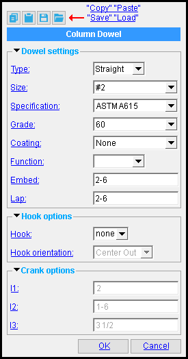
On the Concrete Column Edit or Cast in Place Column Edit window, the name of the leaf for the column dowel " Component " will be " Column Dowel. "
You can edit the tabs using the settings under that leaf, or you can double-click a column dowel to open up this window (shown at left). To open this window, double-click the Column Dowel materials while the " Selection filter " is set to ' Custom Components '.


Red-colored highlighting identifies an entry that is invalid. You need to change that entry, or you will not be able to close this window using " OK ."
-
To begin adding the component, you can click the Add Column Dowel icon or use Add Component . The icon can be found in the command group ' Model--Component ' for the Ribbon Editor.
- See, on this page, to add, edit or delete the column dowel custom component .
Also see :
- Modeling (where custom components can be added)
- Custom components (topic)
- Column Dowel ( Home > Project Settings > Job > Plugin Defaults > Component Plugin Defaults > )
- Copy Component (to copy a column dowel custom component to another column or pilaster)
- Move Component (to move a column dowel custom component to another column or pilaster)
- Explode Component (to reduce the custom component to its constituent materials)
- Component Selection Tool (to search for custom components of a selected type)
- Model Tree (to find custom components and select them for deletion, editing, etc.)
To add, edit or delete the Column Dowel custom component :
Material is generated if the member to which you are adding the column dowels is placed directly on top of another concrete or cast in place column, a concrete pad footing , a grade beam , or a continous footing . That is, the bottom end elevation of the column or pilaster must be the same as the top surface elevation of the member it connects to.
Setup of default settings is available for the edit window that opens when you add this component. See Home > Project Settings > Job > [ Plugin Defaults ] > Components > Component Plugin Setup .
To add the custom component: 1 ) In Modeling , select a concrete column, cast in place column, or pilaster. 2 ) Choose Model > Component > Add . 3 ) On the custom component selection list, choose " Column Dowel " as the custom component you want to add. 4 ) The Column Dowel window opens. Enter the settings that you want, then press " OK " to close the window. 5 ) If User and Site Options > Modeling > " Automatically process after modeling operation " is set to ' Process and create solids ', the dowel will be generated immediately. If not, the dowel will be generated on the column the next time the beam undergoes Process and Create Solids .
Tip: If you use in-tool selection -- that is, select the column or pilaster after selecting " Column Dowel " as the custom component you want to add -- only concrete columns, cast in place columns, and pilasters will be selectable. To edit a Column Dowel component or review its settings, you can find the member it is added to and open its edit window. The component's settings will be contained in that window in a section named [ Column Dowel ]. To edit a Column Dowel custom component without opening the Concrete Column or Pilaster Edit windows, use the Model Tree . You also can use the Selection Filter toolbar item to select the ' Custom Components ' filter and double-click any dowel in the column dowel component to edit the component. The Component Selection Tool can also be used to edit (and find) custom components.
To delete a Column Dowel custom component: 1 ) Use the Component Selection Tool and select the component in the member. Or , select the component in the Model Tree . 2 ) Press the Delete key (or choose Edit > Delete ). 3 ) Process and Create Solids if User and Site Options > Modeling > " Automatically process after modeling operation " is not set to a choice that makes create solids take place automatically.
In the Model Tree , the Column Dowel custom component is listed as Column Dowel when " View By " is set to ' Member piecemark ' or ' Member number ' . The Column Dowel component is listed under its member, after that member's connection components ( Left End and Right End ), and before that member's submaterials.
Column Dowel custom component settings :
| Column Dowel |
 ------ Dowel settings -------
Type: Straight or Cranked . This determines whether or not a crank is modeled at the right end of the rebar shape material.
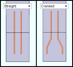
|
A crank can be added at the bottom ends of the dowels. |
If ' Straight ' is selected, no cranks are added. However, a " Hook " can also be added to straight rebar.
If ' Cranked ' is selected, cranks are added to the lower end of the dowel.
Size: A size designation that has been entered to the Rebar Definitions Setup window under the " Active rebar standard ".
Specification: A615 or A706 or etc. This is an ASTM specification entered into the Rebar Specifications window.
The " Steel grade " and " Coating " options are limited to the grades and coating entered into the Rebar Specification window for the selected ASTM specification.
Grade: 60 or 40 or etc. This is the yield strength (grade) of the rebar.
The grade choices in this list box are limited to those entered in the Rebar Specification window for the " Specification " chosen for this rebar shape.
Coating: None or a Coating designation that is available in the " Standard " that you have selected.
A ' Coating ' can be selected from the list box , which includes entries from the Rebar Specification window for the " Specification " chosen for this rebar shape.
Select ' None ' if you do not want a coating. Since it is possible to create specifications that do not have coatings, it is possible that ' None ' may be your only option.
User configuration: If a coating is not available for selection, selecting a different " Specification " will make that coating available if the coating you want is in that other standard. If you don't want to change to a different " Specification ," you can open the Rebar Specifications window and add the coating you want to the specification that you currently have selected.
Function: Blank or VERT BAR or TIE . A usage description from the " Column " section of the Rebar Usage Descriptions window. The " Function " that you enter here is used on the schedules that appear on drawings.
User configuration: To add a " Function " that you can select here, you can add that function to the function type section of the Rebar Usage Descriptions window for the " Column " category.
Embed: The distance (in the primary dimension " Units " or other units ) from the top of the column or pilaster to the bottom of each column dowel; that is, the length of rebar that is embeded in the lower column or pilaster.
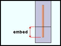
|
The " Embed " and " Lap " distances, when added together, equal the overall length of the dowel. |
Lap: The distance (in the primary dimension " Units " or other units ) from the top of the column or pilaster to the top of each column dowel; that is, the length of rebar that is embeded in the upper column or pilaster.
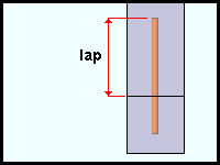
|
The " Embed " and " Lap " distances, when added together, equal the overall length of the dowel. |
------ Hook options -------
Hook: None or 90 or 180 . This option applies when the " Type " is ' Straight '.
' none ' designs straight rebar.
' 90 ' designs 90 degree hooks at the bottom end of the rebar.
' 180 ' designs 180 degree hooks at the bottom end of the rebar.
Hook orientation: Up or down or Left or Right or Center In or Center Out or Horz. In or Horz. out or Vert. In or Vert. Out . This option applies when the " Type " is ' Straight '.
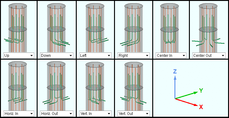
|
| " Hook orientation " settings. In this example, a concrete column is shown with " Straight " column dowels. The pictured UCS icon shows the relation of each orientation to the model's X, Y, and Z coordinates when the column " Rotation " is ' 0 ' degrees. |
------ Crank options ------
l1, l2, and l3: A distance (in the primary dimension " Units " or other units ) for each segment of the crank. These options apply when the Type is ' Cranked '.
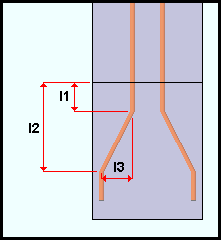
|
" l1 ", " l3 ", & " l3 " options. |
Tip: The dimension entered for " l2 " must be greater than or equal to the " Embed " length, and must be greater than the length of " l1 ."

