 Add Safety Tabs - Column ( Modeling )
Tool summary :
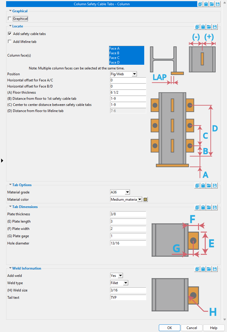
Another way to edit these same settings is to open the the Column Edit window. The name of the Column Edit window section containing safety tab settings is [ Safety Tabs ] .
Tip: The tabs are positioned along the column based on user-specified distances from the floor (which is the " Floor thickness " from the bottom of the column).
Also see :
- Modeling (where custom components can be added)
- Custom components (topic)
- Safety Tabs - Column Setup ( Home > Project Settings > Job > Plugin Defaults > ... )
- Copy Component (to copy the component and its tabs to another column)
- Move Component (to move the component and its tabs to another column)
- Explode Component (to reduce the component to its constituent materials, bolts and welds)
- Component Selection Tool (to search for custom components of a selected type)
- Model Tree (to find custom components and select them for deletion, editing, etc.)
- Tip: If you prefer that safety tabs be spaced from the top of a beam instead of from the bottom of a column, you should consider using the Safety Tabs custom component.
page 1 | contents | add component | model > component > | top
 To add, edit or delete the Safety Tabs - Column custom component :
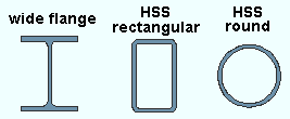
- The Safety Tabs - Column custom component can be added to or edited on wide flange , HSS round (pipe) or HSS rectangular (tube) columns.
- Setup of default settings is available for the edit window that opens when you add this component. The name of the setup window is Column Tabs - Column Setup . In Modeling , it can by opened by choosing Home > Project Settings > Job > Plugin Defaults > Component Plugin Defaults > double-click " Safety Tabs - Column ."
Selecting any material (tab) that is part of the component selects the entire component when the " Selection filter " is set to ' Default ' or ' All ' or ' Custom Components '', 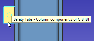
page 1 | contents | add component | model > component > | top
 Safety Tabs - Column custom component settings :
![]() Graphical -----------------------------------------------------------------------------
Graphical -----------------------------------------------------------------------------
Graphical : ![]() or
or ![]() .
.
![]() Locate --------------------------------------------------------------------------------
Locate --------------------------------------------------------------------------------
If this box is checked (
), safety cable tabs will be added to each of the " Column face(s) " that you select. Their placement will be governed by the " Floor thickness " and " Distance from floor to 1st safety cable tab " and the " Center to center distance between safety cable tabs ."
If the box is not checked (
), safety cable tabs will not be added.
If this box is checked (
), a lifeline tab will be added to each of the " Column face(s) " that you select. Their placement will be governed by the " Floor thickness " and the " Distance from floor to lifeline tab "
If the box is not checked (
), lifeline tabs will not be added.
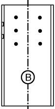
Column face(s): Face A and/or Face B and/or Face C and/or Face D . You must select at least one face to get tabs.
|
face A |
|
|
' Face B ' is web near side of the column.
' Face A ' is the left flange when you are looking at face B.
' Face C ' is the right flange when you are looking at face B.
' Face D ' is web far side of the column, the face opposite to face B.
Position: Flg/Web and/or OS Flg Face+ and/or OSFlgFace- and/or ISFlgFace+ and/or ISFlgFace- .. This applies when you are adding tabs to a wide flange column. The "OS" face is the outside face of the flange. The "IS" face is the inside face of the flange.
Horizontal offset for Face A/C:
Horizontal offset for Face B/D:
Floor thickness: The distance (in the primary dimension " Units " or other units ) from the bottom of the column to the surface of the floor. The " Distance from floor to 1st safety cable tab " and " Distance from floor to lifeline tab " are measured from the floor surface. In the example below, this distance is ft .
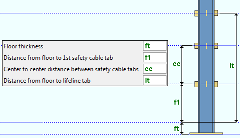
Distance from floor to 1st safety cable tab: The distance (in the primary dimension " Units " or other units ) from the surface of the floor to the center of the 1st (lowest) safety cable tab. In the example below, this distance is f1 . A safety cable tab is centered at half its " Plate length ."

Center to center distance between safety cable tabs: The distance (in the primary dimension " Units " or other units ) from the center of the 1st (lowest) safety cable tab to the center of the next safety cable tab. In the example below, this distance is cc . A safety cable tab is centered at half its " Plate length ."

Distance from floor to lifeline tab: The distance (in the primary dimension " Units " or other units ) from the floor to the center of the lifeline tab. In the example below, this distance is lh . A lifeline tab is centered at half its " Plate length ."

![]() Tab Options ----------------------------------------------------------------------
Tab Options ----------------------------------------------------------------------
Material grade: A36 or A572 or etc. This is the grade of steel for the tabs. This is also the " Steel grade " of the rectangular plate material that each tab is made of.
Setup: If the grade of steel you want is not shown on the list box (
), you can use Home > Project Settings > Job > Plate Grades to add it to to the list.
Material color: A predefined color or a custom color . This is the approximate color of the safety tabs when the column they are submaterials of is displayed in one of the three solid forms . This is also the " Color " of the rectangular plate material that a safety tab is made of.
The predefined colors are set up on the Predefined Colors window. The color swatch next to the list box (
) displays the color that is selected.
Select ' Custom Color ' (last choice on the list) to launch your operating system's color picker and define any color you like.
![]() Tab Dimensions ------------------------------------------------------------------
Tab Dimensions ------------------------------------------------------------------
Plate thickness: The thickness of each of the tabs (in the primary dimension " Units " or other units ). This is also The " Material thickness " of the rectangular plate material that each tab is made of.
Plate length: The length of each of the tabs (in the primary dimension " Units " or other units ). This is also the " Order length " of the rectangular plate material that each tab is made of.
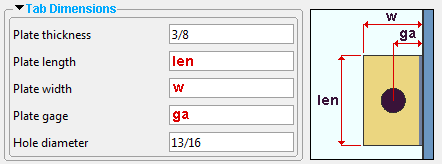
Note: The vertical center of a tab is at half of its " Plate length ." The " Distance from floor to 1st safety cable tab " and " Distance from floor to lifeline tab " and " Center to center distance between safety cable tabs " are each measured to the vertical center of a tab.
Plate width: The width of each of the tabs (in the primary dimension " Units " or other units ). This is also the " Material width " of the rectangular plate material that each tab is made of.

Plate gage: The distance (in the primary dimension " Units " or other units ) from the face of the column to the center of the hole in the tab. Changing the " Gage " moves the hole closer to or further away from the column face.

Note: The " Plate gage " affects the horizontal alignment of the hole -- not its vertical alignment. The hole is vertically aligned at the half-length of the tab.
Hole diameter: The diameter of the hole in each tab (in the primary dimension " Units " or other units ).
![]()
![]() Weld Information ----------------------------------------------------------------
Weld Information ----------------------------------------------------------------
|
|
' Yes ' instructs Safety Tabs - Column to shop weld the tabs to the column.
' No ' instructs Safety Tabs - Column to not add welds.
Weld type: Fillet . This sets the " Weld type " on the Weld Edit window in Modeling as well as the " Weld type " for the weld symbol on the column detail.
| symbol | name | weld used for... |
|
|
fillet | General welding of material. |
Weld size: A distance (in the primary dimension " Units " or other units ) that indicates depth of preparation, size or strength of the weld. This sets the " Weld size " on the Weld Edit window in Modeling as well as the " Weld size " for the weld symbol on the column detail.
Tail text: blank or a text string . This sets the " Supplementary tail text " on the Weld Edit window in Modeling as well as the " Supplementary tail text " for the weld symbol on the column detail.
|
This weld symbol's tail text is TYP . |
If this field is left ' blank ', a tail is not drawn on the weld symbol.
If a ' text string ' is entered, a tail with that text string as the tail text is drawn on the weld symbol.
page 1 | contents | add component | model > component > | top
