 Add Safety Tabs ( Modeling )
Tool summary :
The first time a new Safety Tabs component is added in a new Modeling session, this window is populated with default settings per choices made in Home > Project Settings > Job > Component Plugin Defaults > " Column Safety Tabs ."
- You can click the Add Safety Tabs icon instead of doing steps 2 and 3 of the procedure that follows. The icon can be found in the command group ' Model--Component ' for the Ribbon Editor.
- Preselection method for adding: 1 ) In Modeling , select a beam that frames to a wide flange, HSS round or HSS rectangular column. 2 ) Invoke Add Component . 3 ) On the custom component selection list, choose " Safety Tabs ." 4 ) The Safety Tabs window opens. Specify the end (' Left ' or ' Right ') that the beam frames to the column you want to add the safety cable tabs to. Also specify a " Floor thickness " above the beam along with the distance above the floor that the tabs are to be placed. Press " OK " to close the window. 5 ) If User and Site Options > Modeling > " Automatically process after modeling operation " is set to ' Process and create solids ', the tabs will be generated immediately. If not, the tabs will be generated on the column the next time the beam undergoes Process and Create Solids .
- If you use in-tool selection -- that is, select the beam after selecting " Safety Tabs " as the custom component you want to add -- only beams will be selectable. It is your responsibility to ensure that the beam frames to the column that you want.
- See, on this help page, to add, edit or delete the custom component .
VIDEO 
The Safety Tabs and Safety Tabs - Column custom components are compared.
Also see :
- Modeling (where custom components can be added)
- Custom components (topic)
- Component Plugin Setup ( Home > Project Settings > Job > Component Plugin Defaults > )
- Copy Component (to copy the component to another beam, its tabs to a column attached to that other beam)
- Move Component (to move the component to another beam, its tabs to a column attached to that other beam)
- Explode Component (to reduce the component to its constituent materials and welds)
- Component Selection Tool (to search for custom components of a selected type)
- Safety Tabs - Column (an alternative custom component for adding safety tabs)
- Model Tree (to find custom components and select them for deletion, editing, etc.)
To edit or delete a Safety Tabs custom component :
Selecting one tab that is part of a Safety Tabs custom component selects all of that component's tabs when the " Selection filter " set to ' Default ' or ' All ' or ' Custom Components '', 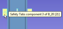
Safety Tabs custom component settings :
![]() Graphical ---------------------------------------------------------------------------
Graphical ---------------------------------------------------------------------------
Graphical : ![]() or
or ![]() .
.
- A Safety Tabs component is automatically set to "
 Graphical " whenever you make graphical changes to any of its materials or welds. For example, when you Edit Material or perform a cut operation on an Safety Tabs material. Click here for more information.
- Instead of allowing the component to be made " Graphical ," you may wish to Explode Component .
![]() Locate -------------------------------------------------------------------------------
Locate -------------------------------------------------------------------------------
|
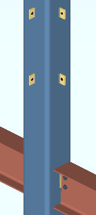
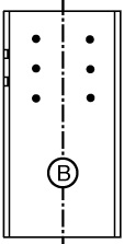
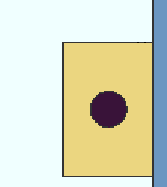
Safety cable tabs on an HSS rectangular column . In this example, the beam that the safety cable tabs were added to is the beam to the right of the column. The user who added the component specified the " Member end " to be ' Left ' since the column is at the left of the beam. |
If this box is checked (
If the box is not checked (
), safety cable tabs will not be added.
If this box is checked (
If the box is not checked (
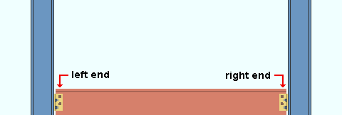
' Left End ' results in the safety tabs being generated on the column that is framed to by the left end of the beam. On the Beam Edit window, the component's settings will appear as left-end settings in a section that is named [ Safety Tabs ].
' Right End ' results in the safety tabs being generated on the column that is framed to by the right end of the beam. On the Beam Edit window, the component's settings will appear as right-end settings in a section that is named [ Safety Tabs ].
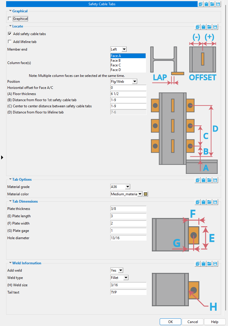
Column face(s): Face A and/or Face B and/or Face C and/or Face D . You must select at least one face to get tabs.
|
face A |
|
|
' Face B ' is web near side of the column.
' Face A ' is the left flange when you are looking at face B.
' Face C ' is the right flange when you are looking at face B.
' Face D ' is web far side of the column, the face opposite to face B.
Position: Flg/Web and/or OS Flg Face+ and/or OSFlgFace- and/or ISFlgFace+ and/or ISFlgFace- .. This applies when you are adding tabs to a wide flange column. The "OS" face is the outside face of the flange. The "IS" face is the inside face of the flange.
Horizontal offset for Face A/C:
Horizontal offset for Face B/D:
Floor thickness: The distance (in the primary dimension " Units " or other units ) from the top of the beam to the surface of the floor. The " Distance from floor to 1st safety cable tab " and " Distance from floor to lifeline tab " are measured from the floor surface. In the example below, this distance is ft .
Distance from floor to 1st safety cable tab: The distance (in the primary dimension " Units " or other units ) from the surface of the floor to the center of the 1st (lowest) safety cable tab. In the example below, this distance is f1 . A safety cable tab is centered at half its " Plate length ."
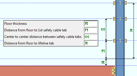
Center to center distance between safety cable tabs: The distance (in the primary dimension " Units " or other units ) from the center of the 1st (lowest) safety cable tab to the center of the next safety cable tab. In the example below, this distance is cc . A safety cable tab is centered at half its " Plate length ."
Distance from floor to lifeline tab: The distance (in the primary dimension " Units " or other units ) from the floor to the center of the lifeline tab. In the example below, this distance is lh . A lifeline tab is centered at half its " Plate length ."
![]() Tab Options ----------------------------------------------------------------------
Tab Options ----------------------------------------------------------------------
Material grade: A36 or A572 or etc. This is the grade of steel for the tabs. This is also the " Steel grade " of the rectangular plate material that each tab is made of.
Setup: If the grade of steel you want is not shown on the list box (
), you can use Home > Project Settings > Job > Plate Grades to add it to the list.
Material color: A predefined color or a custom color . This is the approximate color of the safety tabs when the column they are submaterials of is displayed in one of the three solid forms . This is also the " Color " of the rectangular plate material that a safety tab is made of.
The predefined colors are set up on the Predefined Colors window. The color swatch next to the list box (
Select ' Custom Color ' (last choice on the list) to launch your operating system's color picker and define any color you like.
![]() Tab Dimensions ------------------------------------------------------------------
Tab Dimensions ------------------------------------------------------------------
Plate thickness: The thickness of each of the tabs (in the primary dimension " Units " or other units ). This is also The " Material thickness " of the rectangular plate material that each tab is made of.
Plate length: The length of each of the tabs (in the primary dimension " Units " or other units ). This is also the " Order length " of the rectangular plate material that each tab is made of.
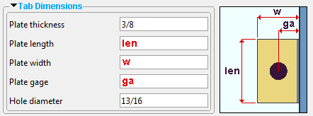
Note: The vertical center of a tab is at half of its " Plate length ." The " Distance from floor to 1st safety cable tab " and " Distance from floor to lifeline tab " and " Center to center distance between safety cable tabs " are each measured to the vertical center of a tab.
Plate width: The width of each of the tabs (in the primary dimension " Units " or other units ). This is also the " Material width " of the rectangular plate material that each tab is made of.
Plate gage: The distance (in the primary dimension " Units " or other units ) from the face of the column to the center of the hole in the tab. Changing the " Gage " moves the hole closer to or further away from the column face.
Note: The " Plate gage " affects the horizontal alignment of the hole -- not its vertical alignment. The hole is vertically aligned at the half-length of the tab.
Hole diameter: The diameter of the hole in each tab (in the primary dimension " Units " or other units ).
![]()
![]() Weld Information ----------------------------------------------------------------
Weld Information ----------------------------------------------------------------
' Yes '
|
' No '
|
' Yes ' instructs Safety Tabs to shop weld the tabs to the column.
' No ' instructs Safety Tabs to not add welds.
Weld type: Fillet . This sets the " Weld type " on the Weld Edit window in Modeling as well as the " Weld type " for the weld symbol on the column detail.
| symbol | name | weld used for... |
|
|
fillet | General welding of material. |
Weld size: A distance (in the primary dimension " Units " or other units ) that indicates depth of preparation, size or strength of the weld. This sets the " Weld size " on the Weld Edit window in Modeling as well as the " Weld size " for the weld symbol on the column detail.
Tail text: blank or a string of characters . This sets the " Supplementary tail text " on the Weld Edit window in Modeling as well as the " Supplementary tail text " for the weld symbol on the column detail.
|
In this example of a weld symbol, the character string TYP is the tail text. |
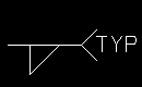
If this field is left ' blank ', a tail is not drawn on the weld symbol.
If a ' string of characters ' is entered, a tail with that character string as the tail text is drawn on the weld symbol.

