General Presentation
- Step-By-Step
- Tips and Tricks
- Related Tools
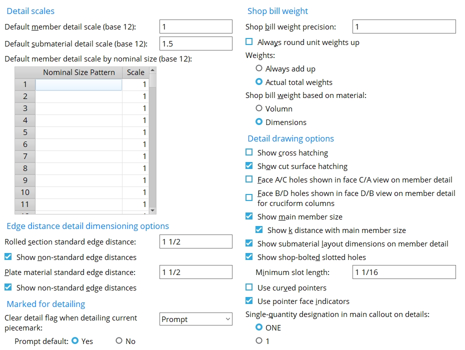
Detailing scales
Default member detail scale (base 12 or base 10): The scale applied to drawings generated when you Detail Members. The words in parenthesis tell you whether to use a 12:1 (base 12) or 10:1 (base 10) scale.
(base 12) means Imperial dimensioning is being used. You should enter the number of inches on to-be-generated member details that you want to represent 1 ft in the shop.
Example: if 1 is entered, 1 inch on the detail equals 1 ft in the shop; if 12 is entered, 12 inches on the detail equals 1 ft in the shop. If 0.125 is entered, 1/8 inch equals 1 ft in the shop.
(base 10) means Metric dimensioning is being used. You should enter the number of millimeters on to-be-generated member details that you want to represent 10 mm in the shop.
Example: If 10 is entered here, 10 mm on the detail equals 10 mm in the shop. If 1 is entered, 1 mm on the detail equals 10 mm in the shop.
To override this default: See Default member detail scale by nominal size. Or you can re-scale a detail using Drawing scale in the Drawing Data Panel after a member is detailed. If you change the Drawing scale inside of the Drawing Data Panel and also choose to Detail from drawing scale, then Detail Members uses that Drawing scale instead of the Default member detail scale that is set here.
Note: Changing the Default member detail scale followed by Detail Members does not affect the Scale of that drawing on the sheet.
Exception: This does not apply to stair member details. The Drawing scale for stair members is set on its edit window.
Default submaterial detail scale (base 12 or base 10): The scale that submaterial details will be drawn to the next time you detail submaterial. It applies regardless of whether or not you choose to Detail using templates. The words in parenthesis tell you whether to use a 12:1 (base 12) or 10:1 (base 10) scale.
(base 12) means Imperial dimensioning is being used. You should enter the number of inches on to-be-generated submaterial details that you want to represent 1 ft in the shop.
Example: if 1 is entered, 1 inch on the detail equals 1 ft in the shop. If 12 is entered, 12 inches on the detail equals 1 ft in the shop. If 0.125 is entered, 1/8 inch equals 1 ft in the shop.
(base 10) means metric dimensioning is being used. You should enter the number of millimeters on to-be-generated submaterial details that you want to represent 10 mm in the shop.
Example: If 10 is entered here, 10 mm on the detail equals 10 mm in the shop. If 1 is entered, 1 mm on the detail equals 10 mm in the shop.
Also see: After a submaterial detail has been generated, it can be re-scaled by adjusting its Drawing scale in the Drawing Data Panel. Its scale on a sheet can be adjusted as the submaterial is Added to the sheet, or by using the Edit Sheet Item window after the submaterial has been placed on a sheet. Be aware that changing the Default submaterial detail scale followed by detail submaterialdoes not affect the Scale of that drawing on the sheet.
Default member detail scale by nominal size (base 12 or base 10): This applies to beams, columns, braces, girts, and purlins. It does not apply to stairs or to custom members such as handrails. If Detail Members cannot find a nominal size pattern from this table and the user has not specified a different scale, member detailing uses the Default member detail scale.
|
||||
| Tip: Cut (Ctrl+x), copy (Ctrl+c) and paste (Ctrl+v) are available as keyboard shortcuts for individual cells on this table. You can also right-click a cell to get a menu with the options Cut, Copy, and Paste. |
During Detail Members, if member detailing finds a Nominal Size Pattern that matches the Material of the member, it uses the scale that is entered here whenever Preserve existing drawing annotations is set to None and the box for Detail from drawing scale is not checked (
).
W24 and w24 are seen as equivalent entries since the search for matching strings that Detail Members performs is not case sensitive.
If a scale is set for the pattern W14x90, Detail Members applies that scale only to members with W14x90 section sizes. If one scale is set for the pattern W14x90, a second scale for W14x9, and a third scale for W14, member detailing will apply the first scale for a W14x90 member, that second scale for a W14x99 member and the third scale for a W14x60 member.
A pattern of W will catch all wide flange members. A pattern of W4 will catch all wide flange members with section sizes that begin with "W4". In the default USA shapes file, for example, that is all section sizes from W40x149 to W44x335.
You can enter a pattern that can recognize any material section size in the local shape file, including channel, angle, W tee, welded plate wide flange, welded plate box, etc.
Example 1: Suppose that when you print detail sheets, you find that sections with thin flange thicknesses, such as a W8x10, are rendered as a single thick line. A larger scale could be set up for W8 or W8x10 sections to prevent this.
Example 2: A common practice in the U.S. steel fabrication industry is to set a scale (base 12) of 1.5 for W-shapes with nominal depths of 6 or less; 1 for nominal depths over 6, up to and including 12; 3/4 for nominal depths over 12.
Also see: The Labels character height, Labels width/height ratio, Weld symbols character height, and dimension Character height and dimension Character width are set independently of the member scale in Drawing Presentation.
Edge distance detail dimensioning options
Rolled section standard edge distance: The distance (in the appropriate Units) from the edge of the material to the center of the first hole. Rolled sections are channel, wide flange, HSS rectangular, angle or HSS round sections.
Effect on drawings: The standard edge distance entered here is referenced during Detail Members if details are generated when the box for Show non-standard edge distances is checked.
Show non-standard edge distances: ![]() or
or ![]() . This applies to rolled sections when you Detail Members (channel, wide flange, HSS rectangular, angle or HSS round sections).
. This applies to rolled sections when you Detail Members (channel, wide flange, HSS rectangular, angle or HSS round sections).
If this box is checked (
), the edge distance will be dimensioned on details where the actual edge distance is something other than that specified as the Rolled section standard edge distance.
Plate material standard edge distance: The distance from the edge of the plate to the center of the first hole.
Effect on drawings: The standard edge distance entered here is referenced during Detail Members when details are generated if the box for Show non-standard edge distances is checked (below). The distance can be overridden by detailing using templates.
Show non-standard edge distances: ![]() or
or ![]() . This applies when you Detail Members.
. This applies when you Detail Members.
If this box is checked (
Marked for detailing
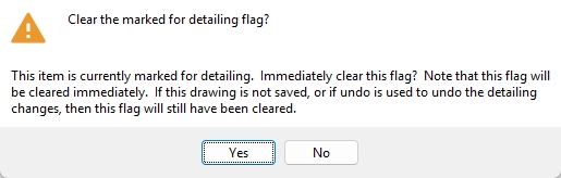
Clear detail flag when detailing current piecemark: Prompt or Immediately or Never.
Prompt opens a window prompting you to select Yes or No to clear the member's marked for detailing flag.
Immediately clears the marked for detailing flag without prompting you.
Never does not clear the marked for detailing flag and does not prompt you.
If set to
Yes, and Clear detail detail flag when detailing current piecemark is set to Prompt, the Yes button on the prompt window is pre-selected.
If set to
Shop bill weight
Shop bill weight precision: A decimal value (from 0.01 to 1). This applies to the bills of material of all member details that currently exist in your current Job, as well as to yet-to-be-created member details.
|
Effect on drawings: The precision entered here is the accuracy to which the reported weight of the material will be rounded on the bill of material. You can see this value reflected in the Unit Weight or Total Weight columns in the Bill Editor, or on a plotted bill of material, or on a Bill of Material Report, or on any other report that is based on the bill of material.
Examples: If you are using metric dimensioning and want the shop bill weight to be calculated to the nearest kilogram, enter 1. If you are using imperial dimensioning and want the shop bill weight to be calculated to the nearest 0.1 pound, enter 0.1.
Always round unit weights up: ![]() or
or ![]() . This applies to the member bill of material that is generated when you Detail Members. It also applies to reports that are based on the bill of material.
. This applies to the member bill of material that is generated when you Detail Members. It also applies to reports that are based on the bill of material.
|
If this box is checked (
If the box is not checked (
Weights: ![]() Always add up or
Always add up or ![]() Actual total weights. This applies to the member bill of material that is generated when you Detail Members. It also applies to reports that are based on the bill of material.
Actual total weights. This applies to the member bill of material that is generated when you Detail Members. It also applies to reports that are based on the bill of material.
|

Note: The stored value for Unit Weight can be shown by doing a right-click. The reported value for Unit Weight is subject to the Shop bill weight precision and whether or not you choose to Always round unit weights up.
Shop bill weight based on material: ![]() Volume or
Volume or ![]() Dimensions. This applies to the member bill of material that is generated when you Detail Members. It also applies to reports that are based on the bill of material.
Dimensions. This applies to the member bill of material that is generated when you Detail Members. It also applies to reports that are based on the bill of material.
Detail drawing options
Show cross hatching: ![]() or
or ![]() . The selection made here applies (where appropriate) when you Detail Members. There is no need to ever show hatch lines on submaterial details.
. The selection made here applies (where appropriate) when you Detail Members. There is no need to ever show hatch lines on submaterial details.
|
If this box is checked (
If the box is not checked (
Show cut surface hatching: ![]() or
or ![]() . The choice made here applies (where appropriate) when you Detail Members or Detail Submaterial.
. The choice made here applies (where appropriate) when you Detail Members or Detail Submaterial.
|
If this box is checked (
If the box is not checked (
Face A/C holes shown on face C/A view on member detail: ![]() or
or ![]() . This applies when you Detail Members and the main material of the member is a flanged section such as wide flange. The top view of a beam detail is shown in the example below.
. This applies when you Detail Members and the main material of the member is a flanged section such as wide flange. The top view of a beam detail is shown in the example below.
|
If this box is checked (
Tip: To adjust the depth check limits of a view, isolate the member in Modeling, open the flange view you want to change, then use the depth check controls followed by Save then detail that member again.
If the box is not checked (
Face B/D holes shown in face D/B view on member detail for cruciform columns: ![]() or
or ![]() . This applies when you Detail Members and the main material of the member is a cruciform section.
. This applies when you Detail Members and the main material of the member is a cruciform section.
If this box is checked (
Tip: To adjust the depth check limits of a view, isolate the member in Modeling, open the flange view you want to change, then use the depth check controls followed by Save then detail that member again.
If the box is not checked (
Show main member size: ![]() or
or ![]() . This applies when you Detail Members.
. This applies when you Detail Members.
|
If this box is checked (
If the box is not checked (
Show k distance with main member size: ![]() or
or ![]() . This applies when you Detail Members only if you have also chosen to
. This applies when you Detail Members only if you have also chosen to ![]() Show main member size.
Show main member size.
|
The values for k distance (detail) (k) and Flange thickness (tf) and Web thickness (tw) and k1 distance (k1) are stored in the local shape file. |
|
If this box and Show main member size are checked (
If this box is not checked (
Show submaterial layout dimensions on member detail: ![]() or
or ![]() . This applies (where appropriate) when you Detail Members. This is a special-case option that applies when showing layout dimensions would cause the sloping hole dimensions to be drawn on the opposite side of the material. This rarely occurs. One special case where it may occur is a gusset plate to the base of a column with a base plate.
. This applies (where appropriate) when you Detail Members. This is a special-case option that applies when showing layout dimensions would cause the sloping hole dimensions to be drawn on the opposite side of the material. This rarely occurs. One special case where it may occur is a gusset plate to the base of a column with a base plate.
|
If this box is checked (
If the box is not checked (
Show shop bolted slotted holes: ![]() or
or ![]() .
.
|
If this box is checked (
If the box is not checked (
Minimum slot length: The minimum length of shop bolted slotted holes that will be shown on subsequently generated details when the box for Show shop bolted slotted holes on details is checked.
| slot length |
|
|
Slot length is the distance between the two points farthest from one another on the perimeter of a slot.
Use curved pointers: ![]() or
or ![]() . This applies, where appropriate, to Detail Members or Detail Submaterial. It also affects Pointer Add.
. This applies, where appropriate, to Detail Members or Detail Submaterial. It also affects Pointer Add.
|
If this box is checked (
Note: You need to restart the Drawing Editor to apply this selection to interactively added pointers.
If the box is not checked (
Also see: Edit Pointer can be used to change pointers from straight to curved or vice-versa. If in the Drawing Editor you double-click an existing pointer and change its curvature, each subsequently added pointer will have the curvature of the last-edited pointer.
Use pointer face indicators: ![]() or
or ![]() . This applies when you Detail Members.
. This applies when you Detail Members.
|
If this box is checked (
If the box is not checked (
Also see: Regardless of the choice made here, you can add or remove a face indicator in the Drawing Editor using Face indicator on the Pointer Edit window.
Single-quantity designation in main callout on details: ![]() ONE or
ONE or ![]() 1. The choice made here applies to the details of members or submaterials whose piecemarks you select when you Detail Members or Detail Submaterial.
1. The choice made here applies to the details of members or submaterials whose piecemarks you select when you Detail Members or Detail Submaterial.
|
||||||||
|
For this option to apply to submaterial details, |


|
|
OK (or the Enter key) closes this screen and applies the settings.
Cancel (or the Esc key) closes this screen without saving any changes.
Reset undoes all changes made to this screen since you first opened it. The screen remains open.
- Settings applied to the General Presentation screen are for your current Fabricator. When you Change Fabricator, you change to a different collection of settings.
- Red or yellow exclamation point icons
 or
or 

