Design Settings
- General Overview
- Tips and Tricks
- Related Tools
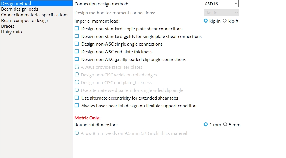
Design method
Connection design method: ASD 16 or ASD 15 or ASD 14 or ASD 13 or ASD 9 or LRFD 16 or LRFD 15 or LRFD 14 or LRFD 13 or LRFD 3 or CISC 12 or CISC 11 or CISC 10 or CISC 9 or CISC 8 or EUROCODE 3 or EUROCODE 3 UK or CHINA GB50017-2003 or INDIA IS800-2007. The method that you select affects connection design, during which system connections are designed.
| Method | Design Specifications |
| ASD 16 |
AISC Steel Construction Manual,
Sixteenth Edition |
| ASD 15 |
AISC Steel Construction Manual,
Fifteenth Edition |
| ASD 14 |
AISC Steel Construction Manual,
Fourteenth Edition |
| ASD 13 |
AISC Steel Construction Manual,
Thirteenth Edition |
| ASD 9 | AISC Manual of Steel Construction, Allowable Stress Design, 9th Edition |
| LRFD 16 |
AISC Steel Construction Manual,
Sixteenth Edition |
| LRFD 15 |
AISC Steel Construction Manual,
Fifteenth Edition |
| LRFD 14 |
AISC Steel Construction Manual,
Fourteenth Edition |
| LRFD 13 |
AISC Steel Construction Manual,
Thirteenth Edition |
| LRFD 3 | Manual of Steel Construction, Load and Resistance Factor Design, 3rd Edition |
| CISC 12 |
CISC Handbook of Steel Construction,
Twelfth Edition |
| CISC 11 |
CISC Handbook of Steel Construction,
Eleventh Edition |
| CISC 10
|
CISC Handbook of Steel Construction,
Tenth Edition |
| CISC 9 |
CISC Handbook of Steel Construction,
Ninth Edition |
| CISC 8 |
CISC Handbook of Steel Construction,
Eighth Edition |
| AS 4100 | Standard for Steel Structures, AS4100 -- 1998 |
| Eurocode 3 | Eurocode 3: Design of steel structures |
| Eurocode3 UK | |
| CHINA GB50017 - 2003 | Code of Design of Steel Structures, GB-50017-03 |
| INDIA IS800-2007 | Indian Standard, General Construction In Steel -- Code of Practice, Third Edition, IS 800: 2007 |
Note: AISC stands for American Institute of Steel Construction. CISC stands for Canadian Institute of Steel Construction. AS 4100 is the Connection design method used in Australia.
Report Writer: Member.LeftEnd.MoreEnd.DesignMethod
Design method for moment connections: Elastic or Plastic. This applies when ASD9 is the Connection design method. The other design methods use the plastic moment capacity.
Effect on 3D modeling: The choice made here affects the calculated design moment applied during connection design of a moment connections when
is selected as the Moment load on the Beam Edit window. The percentage entered (below) to Base beam design moment on % of maximum allowable moment is applied to either the beam's Elastic or Plastic moment strength, depending on the choice made here. Auto
Imperial moment load: kip-in or kip-ft. This applies when the primary dimension Units are set to one of the choices for Imperial....
| Moment load on the Beam Edit window: | |||
|
|||
|
Select
kip-in if you want to enter the Moment load for a beam connection in kip-in. This also affects the
value for Moment load and the value (and units) that are shown on the Connection Design Calculations Report or Expanded Connection Design Calculations Report or on beam details when you choose to Show design loads on details. Select
Note: 1 kip-ft = 12 kip-in.
To convert kip-ft to kip-inches, multiply the kip-ft value by 12 in/ ft. For example, 150.3 kip-ft x 12 in/ft = 1803.6 kip-in.
Design non-standard single plate shear connections: ![]() or
or ![]() .
.
If this box is checked (
If the box is not checked (
), connection design applies the design check and fails single plate shear connections that do not meet it. For more information about the specification for single plate shear connections, please refer to the Manual listed below for your selectedConnection design method.
AISC:
AISC Steel Construction Manual, 16th Edition, pages 10-49 through 51
AISC Steel Construction Manual, 15th Edition, pages 10-88 through 90
AISC Steel Construction Manual, 14th Edition, pages 10-103 through 104
AISC Steel Construction Manual, 13th Edition, pages 10-102 through 103
AISC Manual of Steel Construction: Load & Resistance Factor Design, 3rd Edition, page 10-113
AISC Manual of Steel Construction: Allowable Stress Design, 9th Edition, page 4-52
CISC:
CISC Handbook of Steel Construction, 12th Edition, page 3-76
CISC Handbook of Steel Construction, 11th Edition, page 3-76
CISC Handbook of Steel Construction, 10th Edition, page 3-70
CISC Handbook of Steel Construction, 9th Edition, page 3-70
CISC Handbook of Steel Construction, 8th Edition, page 3-70
Maximum thickness = 0.5 * bolt diameter + 2 mm
Eurocode:
Joints in Steel Construction: Simple Joints to Eurocode 3, Section 5.3
Maximum thickness = 0.5 * bolt diameter for S275
Maximum thickness = 0.42 * bolt diameter for S355
IS 800:
Joints in Steel Construction: Simple Joints to Eurocode 3, Section 5.3
Maximum thickness = 0.5 * bolt diameter for Fy < 280 MPa
Maximum thickness = 0.42 * bolt diameter for Fy <= 280 MPa
Note: This is per regional engineering guidance since IS 800 does not have a specification.
AS 4100:
Australian Institute of Steel Construction: design of structural connections, 4th Edition, Section 4.5.2
Maximum thickness = min(tw + 1 mm, 10 mm)
Note 1: A Search for Non-Standard Single Plate Shear Connections can be used to get a list of all beams with non-standard single plate shear connections. From this list, you can open individual Beam Edit windows.
Note 2: Regardless of whether or not this box is checked, connection design uses the Single Plate Shear Connection Schedule of Minimums to determine the minimum thickness of a shear plate.
Design non-standard welds for single plate shear connections: ![]() or
or ![]() .
.
If this box is checked (
If the box is not checked (
AISC (13th-16th):
AISC Steel Construction Manual, 16th Edition, page 10-49
AISC Steel Construction Manual, 15th Edition, page 10-87
AISC Steel Construction Manual, 14th Edition, page 10-102
AISC Steel Construction Manual, 13th Edition, page 10-101
weld size >= 0.625 * tab thickness
LRFD 3rd and ASD 9th:
Astaneh, 1989 AISC Proceedings, page 3-9
weld size >= 0.75 * tab thickness
CISC:
CISC Handbook of Steel Construction, 12th Edition, page 3-76
CISC Handbook of Steel Construction, 11th Edition, page 3-76
CISC Handbook of Steel Construction, 10th Edition, page 3-70
CISC Handbook of Steel Construction, 9th Edition, page 3-70
CISC Handbook of Steel Construction, 8th Edition, page 3-70
weld size >= 0.75 * tab thickness
Eurocode:
Joints in Steel Construction: Simple Joints to Eurocode 3, page 116
weld throat thickness >= 0.5 * fin plate thickness for S275
weld throat thickness >= 0.6 * fin plate thickness for S355
IS 800:
Joints in Steel Construction: Simple Joints to Eurocode 3, page 116
weld throat thickness >= 0.6 * tab thickness
AS 4100:
Australian Institute of Steel Construction: design of structural connections, 4th Edition, Section 4.5.2
Weld is sized to have greater moment capacity than the web plate
Design non-AISC single angle connections: ![]() or
or ![]() . This applies when the Connection design method is ASD16 or LRFD16 or ASD15 or LRFD15 or ASD14 or LRFD14 or ASD13 or LRFD13 or ASD 9 or LRFD 3. It applies to the design of single-angle connections (Side = Near side or Far side).
. This applies when the Connection design method is ASD16 or LRFD16 or ASD15 or LRFD15 or ASD14 or LRFD14 or ASD13 or LRFD13 or ASD 9 or LRFD 3. It applies to the design of single-angle connections (Side = Near side or Far side).
Page 10-133 of the AISC 14th Edition stipulates the following:
| Single-Angle Connections | |
| Minimum Angle Thickness | Bolt Diameter |
| 3/8 inch (9.5 mm) | 3/4 inch (28 mm) |
| 7/8 inch (22 mm) | |
| 1/2 inch (12 mm) |
1 inch or greater
(24 mm or greater) |
If this box is checked (
If the box is not checked (
Design non-AISC end plate thickness: ![]() or
or ![]() . This applies when the Connection design method is ASD16 or LRFD16 or ASD15 or LRFD15 or ASD14 or LRFD14 or ASD13 or LRFD13 or ASD 9 or LRFD 3.
. This applies when the Connection design method is ASD16 or LRFD16 or ASD15 or LRFD15 or ASD14 or LRFD14 or ASD13 or LRFD13 or ASD 9 or LRFD 3.
If this box is checked (
If the box is not checked (
Design non-AISC axially loaded clip angle connections: ![]() or
or ![]() . This applies when the Connection design method is ASD16 or LRFD16 and the connection is axially loaded. A beam connection is considered axially loaded when the beam member's Tension load and/or Compression load have a value greater than 0, or possibly when Add gusset-beam interface forces to beam is checked on
. This applies when the Connection design method is ASD16 or LRFD16 and the connection is axially loaded. A beam connection is considered axially loaded when the beam member's Tension load and/or Compression load have a value greater than 0, or possibly when Add gusset-beam interface forces to beam is checked on ![]() )
)
If this box is checked (
If the box is not checked (
Always provide stabilizer plates: ![]() or
or ![]() . This applies when ASD14 or LRFD14 is the Connection design method. Per the "Requirement for Stabilizer Plates" specified on page 10-105 of the AISC 14th Edition, "...stabilizing plates are not required when the required shear strength, Ru or Ra, respectively, is equal to or less than the available strength to resist lateral displacement ..."
. This applies when ASD14 or LRFD14 is the Connection design method. Per the "Requirement for Stabilizer Plates" specified on page 10-105 of the AISC 14th Edition, "...stabilizing plates are not required when the required shear strength, Ru or Ra, respectively, is equal to or less than the available strength to resist lateral displacement ..."
|
|
If this box is checked (
If the box is not checked (
Also see: Stabilizer plates may be designed for shear Plate connections to a column web when the option to
Design non-CISC welds on rolled edges: ![]() or
or ![]() . This applies when CISC 8 or CISC 9 or CISC 10 is the Connection design method.
. This applies when CISC 8 or CISC 9 or CISC 10 is the Connection design method.
If this box is checked (
If the box is not checked (
Design non-CISC end plate thickness: ![]() or
or ![]() . This applies when CISC 8 or CISC 9 or CISC 10 or CISC 11 or CISC 12 is the Connection design method. It applies to shear end plates (non-moment end plates).
. This applies when CISC 8 or CISC 9 or CISC 10 or CISC 11 or CISC 12 is the Connection design method. It applies to shear end plates (non-moment end plates).
Page 3-66 of the CISC 10th Edition suggests the following:
"For practical reasons it is suggested that the minimum thickness of the end-plate be 6 mm, and for adequate flexibility, that the maximum thickness be limited to 10 mm."
If this box is checked (
If the box is not checked (
Use alternate weld pattern for single sided clip angle: ![]() or
or ![]() . This applies when CISC 8 or CISC 9 or CISC 10 or CISC 11 or CISC 12 is the Connection design method.
. This applies when CISC 8 or CISC 9 or CISC 10 or CISC 11 or CISC 12 is the Connection design method.
|
|
If this box is checked (
If the box is not checked (
Use alternate eccentricity for extended shear tabs: ![]() or
or ![]() . This option can be used to configure connection design calculations when Use alternate eccentricity is set to Automatic in the
. This option can be used to configure connection design calculations when Use alternate eccentricity is set to Automatic in the ![]() Connection specifications
Connection specifications![]() Extend past flange
Extend past flange
|
The two connection design calculation reports notify you when the alternate eccentricity calculation has been used. |
If this box is checked (
If this box is not checked (
Always base shear tab design on flexible support condition: ![]() or
or ![]() .
.
If this box is checked (
If the box is not checked (
Design Method Single-Plate Shear Connections Shear Tee Connections ASD16 Flexible Only Flexible Only LRFD16 Flexible Only Flexible Only ASD15 Flexible Only Flexible or Rigid LRFD15 Flexible Only Flexible or Rigid ASD14 Flexible Only Flexible or Rigid LRFD14 Flexible Only Flexible or Rigid ASD13 Flexible Only Flexible or Rigid LRFD13 Flexible Only Flexible or Rigid CISC12 Flexible or Rigid Flexible or Rigid CISC11 Flexible or Rigid Flexible or Rigid CISC10 Flexible or Rigid Flexible or Rigid CISC9 Flexible or Rigid Flexible or Rigid CISC8 Flexible or Rigid Flexible or Rigid When the table cell shows
connection design follows the option (
When the table cell shows
connection design will always design the shear connection on a flexible support condition.
Round cut dimensions: 1 mm or 5 mm. This applies when the primary dimension Units are set to Metric. It sets the rounding method that connection design will apply when setting the lengths and widths of shear plates, bent plates, end plates, auto base/cap plates, stiffener plates, etc.
Also see: Round cut dimensions in the Create New Project window sets the choice made here at the time you create a new Job. Home > Project Settings > Fabricator > Standard Fabricator Connections > Preferred Plate Sizes lets you set the thickness of the various plates whose lengths and widths are affected by the choice made here.
Allow 8 mm welds on 9.5 mm (3/8 inch) thick material:
![]() or
or ![]() . This applies when CISC 8 or CISC 9 or CISC 10 or CISC 11 or CISC 12 is the Connection design method. The option is available when Home > Project Settings > Fabricator > Detailing > Drawing Presentation > Primary Dimensions > Units is set to Metric (mm).
. This applies when CISC 8 or CISC 9 or CISC 10 or CISC 11 or CISC 12 is the Connection design method. The option is available when Home > Project Settings > Fabricator > Detailing > Drawing Presentation > Primary Dimensions > Units is set to Metric (mm).
|
CISC Tenth Edition, p 6-172 | ||
If this box is checked (
If the box is not checked (
Beam design loads
Beam shear
End reaction uniform allowable load: Uniform allowable load or Maximum web shear and a percentage.
First select whether you want connection design to calculate the Uniform allowable load or the Maximum web shear. Then enter the percentage you want connection design to multiply this amount by. Connection design uses the selected method and the percentage entered to calculate the design reaction at each end of a beam. This reaction is calculated from the section size properties. The design reaction, in turn, determines the strength of the connection and the
Example: To Beam design reaction, you select Uniform Allowable Load and enter a percentage of 60. For a W18x50, steel grade A572-50, 28 ft span beam, connection design calculates a uniform allowable load of 70 kips. It multiplies this total load by 60% and enters the resulting value of 42 kips as the
Shear load on the Beam Edit window. From the Design Procedure and Notes: The uniform allowable load is the distributed load which causes a simply supported beam of the same length as the member to yield in flexure at the beam's midspan. The maximum web shear is calculated in accordance with Section G2.1 (ASD or LRFD) or Clause 5.11 (AS 4100) or Clause 13.4.1.1 (CISC).
Minimum setup connection: ![]() or
or ![]() . This applies when Automatic is selected for Minimum setup connection under
. This applies when Automatic is selected for Minimum setup connection under ![]() Connection type
Connection type
If this box is checked (
and thus creates a connection on that end of the member with the minimum number of bolt rows, the minimum plate thickness, etc. In the leaf of any affected Beam/Brace Edit window, a green banner notifies you that the connection has been designed with the Minimum setup connection capacity. Loads
If the box is not checked (
loads based on entries made to End reaction uniform allowable load (for beam connections) or Base beam design moment on (for moment connections) or Percent of allowable tension load (for brace connections) or Percent of allowable compression load (for brace connections). Reports: The Connection Design Calculations Report and Expanded Connection Design Calculations Report provide the connection strength for various limit states in either case.
Beam moment
Flange force load factor for moment connection to column flange: A factor from 1 to 2. Refer to AISC specification K1.2 in the Manual of Steel Construction, Allowable Stress Design, 9th Edition. This only applies when ASD9 is the selected Connection design method.
Base beam design moment on % of maximum allowable moment: A percentage from 5 to 200 percent. The percentage is used to calculate the ![]() Auto
Auto
Example: To Beam design moment . . . (this field), you enter a percentage of 80. For a particular section of a particular steel grade used as the Section size for a particular beam, connection design uses the Moment of inertia reported in the local shape file, takes into consideration whether the Plastic or Elastic Design method is used, and calculates a maximum allowable moment of 1000 kip-in. It multiplies this calculated maximum by 80% and enters the resulting value of 800 kip-in as the
Moment load on the Beam Edit window for that beam.
Design moment connections for greater than 100%: ![]() or
or ![]() . This applies to welded beam to column flange moment connections or to a bolted moment end plate to a wide flange column flange. Only the "column side" is designed for the larger moment.
. This applies to welded beam to column flange moment connections or to a bolted moment end plate to a wide flange column flange. Only the "column side" is designed for the larger moment.
If this box is checked (
Moment load on the Beam Edit window is greater than 100% of the maximum allowable moment (a maximum of 125% is allowed). This does not apply to a user-entered Moment load.For a particular moment connection that has been designed for a load exceeding 100% of the allowable, the Connection Design Calculations Report or Expanded Connection Design Calculations Report states, Warning -- The design moment exceeds the beam moment capacity. If this box is not checked (
Moment load (or a user-entered Moment load) is greater than 100% of the beam moment capacity.
Seismic moment connection design: ![]() or
or ![]() . A beam-to-column-flange seismic moment connection can be designed when Seismic moment frame member is set to Yes or, possibly, to Automatic and Seismic moment frame type is set to OMF or IMF or SMF or, possibly, to Automatic and the left- or right-end Moment type is Bolted or Welded. SMF or IMF seismic moment connections can be designed when the Connection design method is any LRFD edition. OMF seismic moment connections can be designed for LRFD and ASD editions.
. A beam-to-column-flange seismic moment connection can be designed when Seismic moment frame member is set to Yes or, possibly, to Automatic and Seismic moment frame type is set to OMF or IMF or SMF or, possibly, to Automatic and the left- or right-end Moment type is Bolted or Welded. SMF or IMF seismic moment connections can be designed when the Connection design method is any LRFD edition. OMF seismic moment connections can be designed for LRFD and ASD editions.
If this box is checked (
If this box is not checked (
Use inner flange plates for beam splice moment: ![]() or
or ![]() . This applies to the design of bolted moment beam splices when, in the
. This applies to the design of bolted moment beam splices when, in the ![]() Moment
Moment
|
|
If this box is checked (
If the box is not checked (
Auto-calculate tying loads: ![]() or
or ![]() . This affects whether or not the Tie force on the Beam Edit window is checked
. This affects whether or not the Tie force on the Beam Edit window is checked ![]() )
)![]() )
)
If this box is checked (
If the box is not checked (
Seismic moment frame type: OMF or IMF or SMF. This applies when Automatic is selected for Seismic moment frame type under ![]() Seismic
Seismic
OMF instructs connection design to use "Ordinary Moment Frame" design. This design code is only recommended for non-seismic or low seismic regions since such frames provide less resistance to lateral motion than do IMF or SMF seismic moment resisting frames.
IMF instructs connection design to use "Intermediate Moment Frame" design. IMF seismic moment resisting frames should only be installed in moderate seismic regions.
SMF stands for "Special Moment Frame" design code for seismic moment connections. SMF seismic moment resisting frames are designed to resist flexural, axial, and shearing actions that result as a building sways through multiple inelastic displacement cycles due to a strong earthquake.
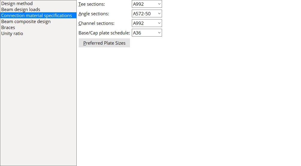
Connection material specifications
Tee sections: A36 or A441 or A588 or etc. This is the steel grade used for tee connection materials on system connections. For instance, in the connection design of tee seats and tee shear connections.
Setup: If the steel grade you want is not shown as a menu option (
), you can add it to Project Settings > Job > Material Grades > WT Grades. The Standard Fabricator Connections window Preferred WT Sizes lists tee sections that connection design can use for tee seats and tee shear connections.
Angle sections: A36 or A441 or A588 or etc. This steel grade is used for angle connection materials on system connections. For instance, in the connection design of clip angles.
Setup: If the steel grade you want is not shown as a menu option
( , you can add it to Project Settings > Job > Material Grades > Angle Grades. The Project Settings > Fabricator > Standard Fabricator Connections > Preferred Connection Material Sizes > Peferred Angle Sizes screen lists angle sections that connection design can use for angle seats, bolted angle moment connections and offset beam-to-beam framing.
Channel sections: A36 or A441 or A588 or etc. This steel grade is used for channel connection materials on system connections. For instance, in the connection design of channel splices.
Setup: If the steel grade you want is not shown as a menu option
( , you can add it to Home > Project Settings > Job > Material Grades > Channel Grades. Home > Project Settings > Fabricator > Standard Fabricator Connections > Column Splice Settings lists channel sections that connection design can use for column splices.
Base/Cap Plate Schedule: A36 or A441 or A588 or etc. This steel grade applies to plate definitions for which Default (xxx) is selected on the list box ![]() )
)
Example: Suppose that Default (A36) is selected for three plate definitions, and you change the selection made here from A36 to A588. The next time you open the Base/Cap Plate Schedule, you will find that the steel grade applied to the three plate definitions is Default (A588).
Setup: If the steel grade you want is not shown as a menu option
( , you can add it to Project Settings > Job > Material Grades > Plate Grades.
Preferred Plate Sizes: Opens the same Preferred Plate Sizes screen that is found in Project Settings > Fabricator > Standard Fabricator Connections > Preferred Connection Material Sizes where you can assign steel grades for plates by connection type.
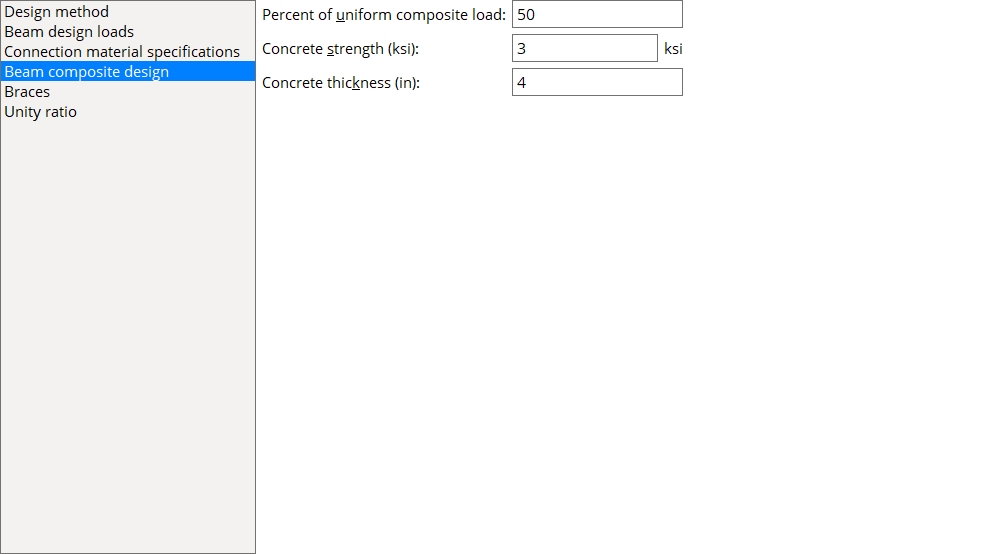
Beam composite design
Percent of uniform composite load: A percentage. A beam composite section is any beam with the Composite Design option checked ![]() )
)
▸ Multiply the calculated shear load for a non-composite section by an Rx factor entered to the Composite Reaction Factor Schedule.
▸ If 1 is entered on the Composite Reaction Factor Schedule for a beam of a particular nominal depth, connection design calculates the uniform composite load for that beam based on that beam's section properties and the Concrete strength and Concrete thickness.To calculate the Shear load for each end of the composite beam, connection design multiplies the percentage entered here by the calculated uniform composite load.
Concrete strength (ksi or MPa): A value in kips/sq. inch or MPa, depending on the primary dimension Units.
Effect on 3D modeling: The concrete strength entered here is used to calculate the uniform composite load for beams with the box for Composite design checked if that beam has a nominal depth for which an Rx factor of 1 is entered on the Composite Reaction Factor Schedule.
Concrete thickness: The concrete thickness.
Effect on 3D modeling: The concrete thickness entered here is used to calculate the uniform composite load for beams with the box for Composite design checked if that beam's Section size has a nominal depth for which an Rx factor of 1 is entered on the Composite Reaction Factor Schedule.
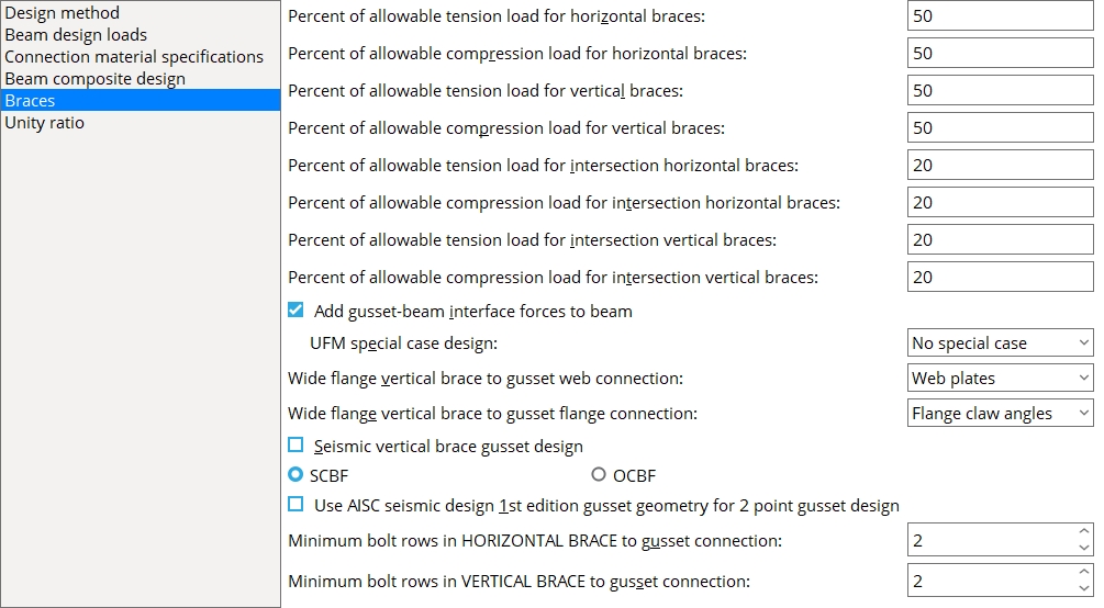
Braces
Percent of allowable tension load for horizontal braces: A percentage (up to 100 percent) of the brace's gross tension capacity calculated in accordance with Section D2 (ASD or LRFD) or Clause 7.2 (AS 4100) or Clause 13.2 (CISC).
Connection design uses the percentage entered here to calculate the left/right
Tension load on a horizontal brace's edit window.
Percent of allowable compression load for horizontal braces: A percentage (up to 100 percent) of the brace's compression load capacity calculated in accordance with Section E3 (ASD or LRFD) or Clause 6.3 (AS 4100) or Clause 13.3 (CISC).
Connection design uses the percentage entered here to calculate the left/right
Compression load on a horizontal brace's edit window.
Percent of allowable tension load for vertical braces: A percentage (up to 100 percent) of the brace's gross tension capacity calculated in accordance with Section D2 (ASD or LRFD) or Clause 7.2 (AS 4100) or Clause 13.2 (CISC).
Connection design uses the percentage entered here to calculate the left/right
Percent of allowable compression load for vertical braces: A percentage (up to 100 percent) of the brace's compression load capacity calculated in accordance with Section E3 (ASD or LRFD) or Clause 6.3 (AS 4100) or Clause 13.3 (CISC).
Connection design uses the percentage entered here to calculate the left/right
Compression load on a vertical brace's edit window.
Percent of allowable tension load for intersection horizontal braces: A percentage (up to 100 percent) of the allowable tension load of the intersected horizontal brace. This value is applied to the intersecting brace, if it is single-sided.
|
The intersecting horizontal brace is the brace that frames to the intersected brace. |
A single sided intersection brace can act as a support for the intersected brace. Consequently, connection design uses the percentage entered here to calculate -- from the intersected brace's gross tension load capacity -- the left/right
Tension load on the intersecting horizontal brace's edit window.
Percent of allowable compression load for intersection horizontal braces: A percentage (up to 100 percent) of the allowable compression load of the intersected horizontal brace. This value is applied to the intersecting brace, if it is single sided.
|
|
The intersecting horizontal brace is the brace that frames to the intersected brace. |
A single sided intersection brace can act as a support for the intersected brace. Consequently, connection design uses the percentage entered here to calculate -- from the intersected brace's gross tension load capacity -- the left/right
Compression load on the intersecting vertical brace's edit window.
Percent of allowable tension load for intersection vertical braces: A percentage (up to 100 percent) of the allowable tension load of the intersected vertical brace. This value is applied to the intersecting brace, if it is single-sided.
|
The intersecting vertical brace is the brace that frames to the intersected brace. |
A single sided intersection brace can act as a support for the intersected brace. Consequently, connection design uses the percentage entered here to calculate -- from the intersected brace's gross tension load capacity -- the left/right
Tension load on the intersecting vertical brace's edit window.
Percent of allowable compression load for intersection vertical braces: A percentage (up to 100 percent) of the allowable compression load of the intersected vertical brace. This value is applied to the intersecting brace, if it is single sided.
|
|
A single-sided intersecting vertical brace can act as a support for the intersected brace. |
A single sided intersection brace can act as a support for the intersected brace. Consequently, connection design uses the percentage entered here to calculate -- from the intersected brace's gross tension load capacity -- the left/right
Compression load on the intersecting vertical brace's edit window.
Add gusset-beam interface forces to beam: ![]() or
or ![]() . This applies when a vertical brace frames to a beam and column. In such a framing situation, the Uniform Force Method of design transfers brace forces into the beam connection. This field gives you the option of applying those forces to the design of the beam connection.
. This applies when a vertical brace frames to a beam and column. In such a framing situation, the Uniform Force Method of design transfers brace forces into the beam connection. This field gives you the option of applying those forces to the design of the beam connection.
|
|
|
||||
|
|
If this box is checked (
If the box is not checked (
UFM special case design: No special case or Special case 2 or Special case 3. This applies when Automatic is selected for UFM special case design under ![]() Connection specifications
Connection specifications
|
|
|
No special case specifies that connection design distribute the brace's vertical force to the beam as well as to the gusset-to-column connection. This minimizes the size of the gusset plate, but may result in the beam connection failing under heavily loaded conditions. See The Uniform Force Method, AISC 14th Edition, p 13-3.
Special case 2 instructs connection design to distribute the brace's vertical force to the gusset-to-column connection instead of to the beam. As a result, the beam's vertical reaction is not increased. This may prevent the beam connection from failing if the beam is highly loaded, but also may add rows to the column connection and thus cause the gusset plate to be larger. See Special Case 2, Minimizing Shear in the Beam-to-Column Connection, AISC 14th Edition, p 13-7.
Special case 3 instructs connection design to connect the vertical brace to the beam, but not to the column. See Special Case 3, No Gusset-to-Column Web Connection, AISC 14th Edition, p 13-7. Be aware that special case 3 does not apply to gusset-to-column flange connections. For gusset-to-column flange connections, the connection will be designed as if No special case has been selected.
Wide flange vertical brace gusset web connection: None or Web plates or Channels. This applies when Standard connection is selected as the Connection arrangement for a wide flange vertical brace whose Web orientation is Vertical and when Automatic is selected for Web connection type under ![]() Connection specifications
Connection specifications
|
|
None can get you an automatic connection when the Wide flange vertical brace gusset flange connection (below) is set to Flange claw angles. That connection will consist of flange claw angles without a web connection.
Web plates can get you an automatic connection when the Wide flange vertical brace gusset flange connection (below) is set to Flange claw angles or to None. The NS and FS web plates will connect the web of the web-vertical wide flange vertical brace to the gusset plate.
Channels can get you an automatic connection when the Wide flange vertical brace gusset flange connection (below) is set to None. A channel web connection consists of NS and FS channels that connect the web-vertical wide flange vertical brace to the gusset plate.
Permitted configurations: 1) Web plates only. 2) Web channels only. 3) Web plates with flange angles. 4) Flange angles only.
Not permitted: Channels with claw angles cannot be designed. Instead of a connection, you get the failure message Incompatible web and flange connection types.
Wide flange vertical brace gusset flange connection: None or Flange claw angles. This applies when Standard connection is selected as the Connection arrangement for a wide flange vertical brace whose Web orientation is Vertical and when Automatic is selected for Flange connection type under ![]() Connection specifications
Connection specifications
|
|||||||||
| The left and middle brace connections have the same Tension load.The flange-angles-only connection (on the right) has a smaller Tension load. |
None specifies that connection design attempt to design a Standard connection that does not use claw angles
Flange claw angles instructs connection design to design a Standard connection that uses claw angles to connect the wide flange vertical brace's flanges to the gusset plate. The shape of the gusset is adjusted to permit the flange angles to fit.
Permitted configurations: 1) Web plates only. 2) Web channels only. 3) Web plates with flange angles. 4) Flange angles only.
Not permitted: Channels with claw angles cannot be designed. Instead of a connection, you get the end connection failure message Incompatible web and flange connection types.
Seismic vertical brace gusset design: ![]() or
or ![]() . A seismic vertical brace can be designed for any vertical brace framing situation, so long as the brace is a valid material type. This applies when Automatic is selected for Seismic brace under
. A seismic vertical brace can be designed for any vertical brace framing situation, so long as the brace is a valid material type. This applies when Automatic is selected for Seismic brace under ![]() General settings
General settings
|
|
||||
| In the left example, one construction line is drawn along the end of the brace. The other passes through the corner of the gusset. The same construction lines are in the right example. | |||||
If this box is checked (
is selected for the vertical brace's Tension load and/or Compression load, connection design creates a connection with seismic loading on that end of the vertical brace. If is not selected for Tension and/or Compression load, connection design still creates a seismic gusset plate if SCBF is selected. For HSS rectangular/TS seismic braces, connection design provides reinforcement plates. If the box is not checked (
Steel grade setup for seismic design
Factors controlling
(per section I-6 of the AISC Seismic Design Manual)Steel grade setup Tensile strength Yield strength wide flange Rt Ry angle Rt Ry channel Rt Ry welded plate W Rt Ry HSS rectangular / TS Rt Ry round bar Rt Ry W tee Rt Ry HSS round / pipe Rt Ry
![]() SCBF or
SCBF or ![]() OCBF: This applies to vertical braces when Seismic brace is set to Yes (or to Automatic with
OCBF: This applies to vertical braces when Seismic brace is set to Yes (or to Automatic with ![]() Seismic vertical brace gusset design
Seismic vertical brace gusset design
| The same user tension load was applied to all three of these examples. | |||||||||||
|
|
|
|||||||||
|
The left and right gusset plates are the same. Only the middle gusset is unique. If the applied load for all of these examples was an |
|||||||||||
Use AISC seismic design 1st edition gusset geometry for 2 point gusset design: ![]() or
or ![]() . This applies to the design of 2-point vertical brace gusset plates when Seismic brace is set to Yes (or to Automatic with
. This applies to the design of 2-point vertical brace gusset plates when Seismic brace is set to Yes (or to Automatic with ![]() Seismic vertical brace gusset design
Seismic vertical brace gusset design![]() Connection specifications on the Vertical Brace Edit window or at Home > Project Settings > Job > Connections > User Defined Connections is set to Automatic.
Connection specifications on the Vertical Brace Edit window or at Home > Project Settings > Job > Connections > User Defined Connections is set to Automatic.
|
||
| The 1st edition AISC seismic design manual specifies more cuts for 2-point gusset plates than does later editions of that same manual. |
If this box is checked (
If the box is not checked (
Minimum bolt rows in horizontal brace to gusset connection: The minimum number (1 or 2 or 3, etc.) of rows of bolts that you want to be allowed for connecting a horizontal brace to its gusset plate. If needed, connection design will increase the number of bolt rows in order to create a connection that will stand up to the load. By default, the minimum is set to 2, which is the minimum that connection design used before this became a user-settable option.
minimum = 1
 |
minimum = 2
 |
minimum = 3
 |
Minimum bolt rows in vertical brace to gusset connection: The minimum number (1 or 2 or 3, etc.) of rows of bolts that you want to be allowed for connecting a vertical brace to its gusset plate. If needed, connection design will increase the number of bolt rows in order to create a connection that will stand up to the load. By default, the minimum is set to 2, which is the minimum that connection design used before this became a user-settable option. This option does not apply to HSS erection bolts."
minimum = 2
 |
minimum = 3  |
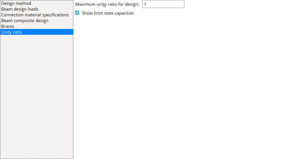
Unity ratio
Maximum unity ratio for design: The maximum Unity Ratio value used by connection design. The default value is 1.0.
Show limit state capacities:
![]() or
or ![]() . This applies when Maximum unity ratio for design is set to 1.0. Showing limit state capacities is not valid if the Maximum unity ratio for design does not equal 1.0. When Maximum unity ratio for design is not set to 1.0, this option will be disabled. The limit state capacities will not be shown in member edit windows, Expanded Calculations, and Design (shorter) Calculations reports.
. This applies when Maximum unity ratio for design is set to 1.0. Showing limit state capacities is not valid if the Maximum unity ratio for design does not equal 1.0. When Maximum unity ratio for design is not set to 1.0, this option will be disabled. The limit state capacities will not be shown in member edit windows, Expanded Calculations, and Design (shorter) Calculations reports.
If this box is checked (
If the box is not checked (
(Member Edit)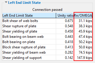
(Member Edit)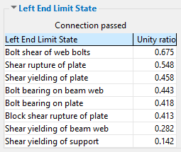
(Expanded Calculations)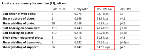
(Expanded Calculations)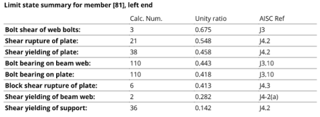
(Design (short) Calculations)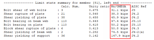
(Design (short) Calculations)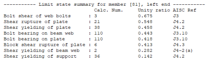


|
|
OK (or the Enter key) closes this screen and applies the settings.
Cancel (or the Esc key) closes this screen without saving any changes.
Reset undoes all changes made to this screen since you first opened it. The screen remains open.

- If you have made changes to this window and want to ensure connection design consistency throughout your current Job, you should interactively mark for processing (or Process Selected) all members in your current Job, then Process and Create Solids.
- You can get a print-out of general specifications that are used for connection design by generating a Design Procedure and Notes report.
- The actual design calculations that connection design employs for specific connections in the 3D model can be output to a Connection Design Calculations Report or to an Expanded Connection Design Calculations Report.
- Red or yellow exclamation point icons
 or
or 

