 Custom Profile Material Add
- General Overview
- Step-By-Step
- Tips and Tricks
- Related Tools
![]() Show images displays drawings that depict the dimensions that are controlled by connection design locks (if images are found).
Show images displays drawings that depict the dimensions that are controlled by connection design locks (if images are found).
![]() Overlay displays one leaf at a time. When you select a leaf, either from the tree on the left or from inside the window itself, all other leaves collapse.
Overlay displays one leaf at a time. When you select a leaf, either from the tree on the left or from inside the window itself, all other leaves collapse.
![]() Copy, Paste, Save, Load buttons:
Copy, Paste, Save, Load buttons:
- The position of these "form" buttons on the window tells you what settings they apply to. Click here for more information.
- You can
 Copy the settings on this window, then
  Paste those settings to a different edit window of the same type.
- You can
 Save the settings on this window to a file stored in a global folder that is used by your current version of SDS2. Give the file a name that will help other users identify its purpose. You can
  Load a saved file to replace the settings on this window (except Piecemark) with the settings that are stored in the file you select.
- When editing multiple windows at the same time, Paste and Load replace mixed entries to a single field with a single entry. Copy and Save ignore fields with mixed entries, treating them as if they have no entry or do not exist.
General Information opens the General Information window, which provides additional information and settings that pertain to this material.
Tip: You can use the General Information window to change the material's X, Y, or Z global coordinates (and thus reposition the material within the 3D model).
Also: A Properties button at the bottom of the General Information window lets you Edit Properties for this material.
OK (or the Enter key) closes this window and applies the settings on it to the material(s).
Defaults: Even if you did not make any changes on this window, pressing OK causes many of the General settings on this window to be applied as the defaults for the next material of the same type that is added in your current session of Modeling.
If you opened this window to edit a single material (single-edit), the Change All Options & Warning List opens after you press the OK button. You can use that window to cancel your changes or, if other materials with the same submaterial piecemark exist, apply your changes to those other materials. Also, if a Cut On Plane or related cutting/bending/fit operation (that does not get stored in the Material Operations window) was previously done on this material, you are given the option to undo that operation.
If you opened this window to edit multiple materials (multi-edit), the Change All Options & Warning Listdoes not open after you press the OK button. Also, if a Cut On Plane or related cutting/bending/fit operation (that does not get stored in the Material Operations window) was previously done on this material, you are not given the option to undo that operation.
Cancel (or the Esc key) closes this window without saving any changes.
Possibilities: If you are adding a new material, Cancel brings you back to the work point location step (step 2) in the add operation. For an edit material operation, Cancel ends the operation.
Tip: When you open this window to review information only -- and you do not want to set the defaults for the next-added rectangular plate -- the best way to close this window is to press Cancel.
Reset undoes all changes made to this window since you first opened it. The window remains open.
Note: The settings shown on this window when it first opens for the adding of a material are the settings of the last-added or last-edited material of the same type (unless you exit Modeling in the meantime).
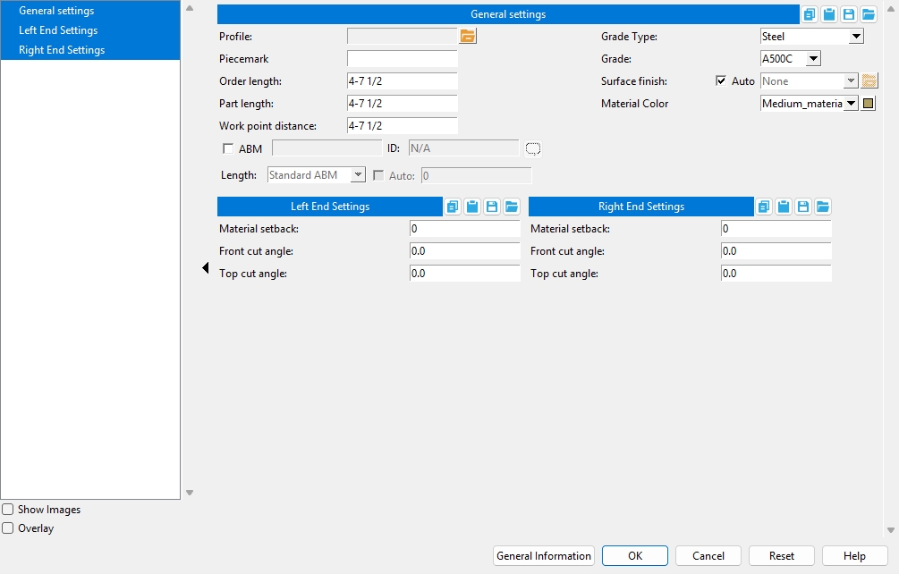
General Settings
Profile: The custom profile shape as shown in the shape selector window.
Piecemark: Blank or any character string (up to 61 characters). This is the submaterial mark.
Parametric module:MinorMark
Report Writer:MemberMaterial.Material.MinorMarkOrder length: The distance measured from the furthest point on the material's left end to the furthest point on the material's right end.
Note: Where one end or both ends of the rolled section are cut at an angle, the Order length may be longer than the Work point distance. The Order length is automatically updated on this window when you make changes to the following fields: Work point distance, Material setback, Front cut angle, Top cut angle.
Report Writer:XXXXX.OrderLength
Advanced Selection:OrderLength
Parametric module:OrderLengthPart length: read-only The distance measured from the furthest point on the material's left end to the furthest point on the material's right end. Unlike the Order length, this distance is measured after end cuts are made to the material. In most cases, the Part length and Order length are exactly the same.
Report Writer:XXXXX.PartLength
Advanced Selection:PartLength
Parametric module:PartLengthWork point distance: The distance between the work points of the custom profile material.
Note: The distance between work points entered here is measured from the first located point of the material. If you change this distance, your change is reflected in the Order length field on this window.
Report Writer:XXXXX.WorkpointSlopeDistance
Advanced Selection:WorkpointSlopeDistance
Parametric module:WorkpointSlopeDistanceGrade Type: The material grade type, which is populated from the Custom Profile Grades.
Grade: Sets the grade of the member's main material. The grades available are determined by the selected Grade Type.
Report Writer:MemberMaterial.Material.SubMaterial.MaterialGradeDescription
Advanced Selection:MaterialGrade
Parametric module:MaterialGradeSurface finish: None or Sandblasted or Red oxide or Yellow zinc or Gray oxide or Blued steel or Galvanized or Duplex Coating or Undefined 1 or Undefined 2 or Undefined 3 or Red oxide 2 or Any user added surface finish. This affects the colors of Solid members on erection views in the Drawing Editor . This also sets the color when Output material color is set to Surface finish for a VRML Export or a DWG/DXF Export. The Color (notSurface finish) sets the color of this material in Modeling .
sand blasted red oxide yellow zinc user surface finish 1 gray oxide blued steel galvanized user surface finish 2 To assign a different surface finish, you can drop-down the current surface finish and select the one you want, or you can press the
Auto
or
If this box
If the box
is not checked, the material surface finish can be changed to whatever is available in the list of surface finishes. If the surface finish changes from what the member level has set, the auto checkbox will be unchecked automatically. When the auto check box is unchecked, the member edit window shows an information tag which notifies the user that an attached material is not following what was set on the member level.
Note 1:Submaterial piecemarks can be split apart by surface finish. All surface finishes that do not have the Break Marks Material checked on can be applied to any like material with out the material splitting. If the Break Marks Material is checked on then only like materials with that specific surface finish can have the same piecemark, and because the submaterial marks differ so would the member's piecemark.
Note 2: When exporting a KISS file using "model" as the Data source surface finish data on the materials are compiled into the KISS download as follows, with a few exceptions (G=galvanized, N= none or sandblasted, P= others). Those exceptions are:
If the box for Finish routing in KISS export setup is set to a user routing
If the user has adjusted the Abbreviation for any of the default provided surface finishes
If you are using a user added surface finish
In these cases you will get what is provided in either the User routing, or the abbreviation field. For other exports it will always provide the abbreviation in the 'surface finishes' settings page.
Tip 1: Surface area is reported on the General Information window -- and this can be used to estimate the amount of coating required and its cost.
Tip 2: Changing Grade, Color, and Surface finish do not cause the plate to be regenerated. This means that, if you change those settings only, material fit operations such as a Fit Exact may optionally be preserved.
Report Writer: MemberMaterial.Material.SurfaceFinish
Setup: Surface Finish SettingsMaterial Color: A predefined color or a Custom Color . This is the approximate color of the custom profile material when it is displayed in one of the three solid forms .
The predefined colors are set up on the Predefined Colors window. The color swatch next to the list box (
) displays the color that is selected.
Select Custom Color (last choice on the list) to launch your operating system's color picker and define any color you like.
Report Writer:MemberMaterial.Material.MaterialColor3dRed
Report Writer:MemberMaterial.Material.MaterialColor3dGreen
Report Writer:MemberMaterial.Material.MaterialColor3dBlueLeft/Right End Settings
Material Setback: The distance measured parallel with the workline of the member from the work point for this end of the member to the member's main material.
Front Cut Angle: A positive or negative angle from 89 to -89 degrees. With the left end of the material to your left on the screen, a positive angle is measured counterclockwise from a line perpendicular to the workline, and a negative angle is measured clockwise. 0 designates that no cut is made.Top Cut Angle: A positive or negative angle from 89 to -89 degrees. This is the angle at which both the top and bottom side of the custom profile material are to be cut. 0 designates that no cut is made.
1. Click the Add Material icon. The icon can be found on the Material page > Add section. Select Custom Profile Member. Select a member you want to add the material to.
Alternative: Invoke Custom Profile using the Find Tool by searching the command name and clicking the icon, which is pictured above. Select a member you want to add the material to.
Learn more about alternative methods for launching commands.
2. The status line prompts, Add: Custom Profile Member. Select a Locate option, then left-click (Locate) to place two work points to define the work line (and X material axis) of the custom profile to be between those two points. The direction you select (left-to-right versus right-to-left) does determine the material rotation.
Alternative: Right-click (Return) or press the Esc button to end the operation at any time.
3. The custom profile material window opens, on it are the settings for the custom profile material. When you are done changing or reviewing the settings, press the OK button to close the window.
4. The Rotate Material window opens, and a preview of the to-be-added custom profile is shown on screen. Rotate the material as needed, press the OK button.
5. The status line prompts, Add: Custom Profile, allowing you to continue adding custom profile members by repeating steps 2-4.
Alternative: Middle-click (Repeat) to add another custom profile member with the exact same attributes as the previously added custom profile.

