Exporting a CIS2 Model
- General Overview
- Step-By-Step
- Tips and Tricks
- Related Tools
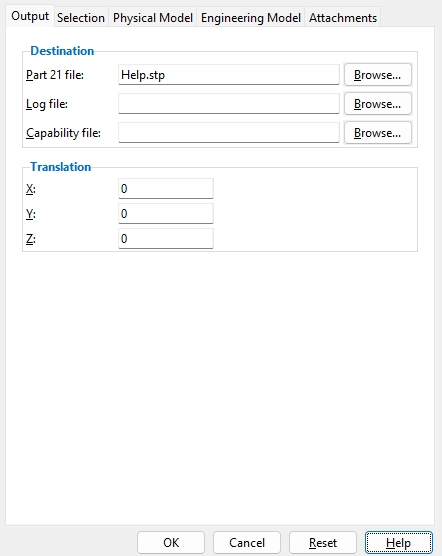
Output
Destination
Part 21 file: The file name of the CIS2-compliant file that you want to generate. The default file name is the name of your current Job plus an .stp extension. The default folder into which this file is placed is set per User and Site Options > Output > Export Model.
To place the file elsewhere or give it a different name, press the Browse... button, then open the
file folder into which you want the file placed, type in a File name, then press the Save button.
Log file: The file name of the log file that is generated when the Part 21 file is created. This log tells you the filename of the Part 21 file, the CIMsteel Integration Standards used, and the total number of entities exported to the file. Unless you specify otherwise, the file is placed in the Destination that is specified on the Export Model window.
To place the file elsewhere or give it a different name, press the Browse... button, then open the
Capability file: This is a file that lists the capabilities of a Part 21 file created using Export Model. You can compare this file with the capability file of the importing program to which you are exporting the Part 21 file.
Translation
Translation: 0 or a positive/negative distance. Each member’s work points have specific global X, Y, and Z coordinates at both ends in the 3D model. To move all members in the exported file by a set amount along X, Y, and/or Z, enter that distance here.
0for X and Y and Z exports a model with the same origin ( 0, 0, 0 global coordinate ) as the model in your current Job.
A positive distanceadds to the X, Y or Z coordinates of all exported members.
A negative distancesubtracts from the X, Y or Z coordinates of all exported members.
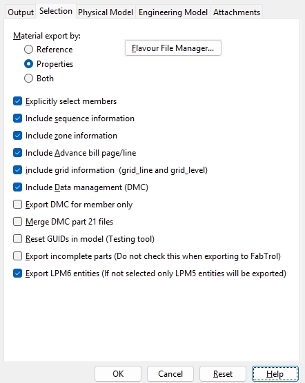
Selection
Material export by: Reference or Properties or Both .
Reference: Exports section sizes (W18x40, C10x20, etc.) to be listed in the Part 21 file by a standard reference to a flavour file instead of having the properties of that section size in the Part 21 file itself.
Properties: Exports the properties ( Depth , Flange width , etc.) of each section size explicated in the Part 21 file.
Both: Exports the section sizes to be listed in the Part 21 file by their standard reference to a flavour file and also to have the properties of each section size fully explicated in the Part 21 file.
Flavour File Manager... opens the Choose Flavour Files window. A flavour file is a standard reference file published by organizations such as AISC. These files are not created by the Export Model function and must be obtained directly or indirectly from the publishing organization. Currently, all flavour files that can be referenced by a Part 21 file generated with Export Model are shape files.
1 . After you have selected Reference for Material exported by :
1a : Press the Flavour File Manager button.
2 . A notification dialog will appear on screen with the message: You have just entered the Flavour File Manager .
2b : Press the OK button to continue.
3 . The Choose Flavour Files window opens. On it is a list of the flavour files that may be referenced in the Part 21 file.
Optional: Press the Add button to add a new flavour file to the list.
Optional: Select flavour file(s) on the list and press the Delete button to remove them from the list.
Alternative 1 : Press OK to close the Flavour File Manager and keep your changes to the list of flavour files.
Alternative 2 : Press Cancel to close the Flavour File Manager without saving any of your changes to the list of flavour files.
Explicitly select members: ![]() or
or ![]() .
.
opens a selection dialog after your press the OK button. On this selection dialog, you can select which members you want to include in the Part 21 file.
causes all members in your current Job to be output to the Part 21 file. This applies regardless of whether you are doing the export from Home or Modeling or the Drawing Editor .
Include sequence information: ![]() or
or ![]() .
.
Include zone information: ![]() or
or ![]() .
.
Include advance bill page-line: ![]() or
or ![]() .
.
Member and material edit windows: ID
Include grid information ( grid_line and grid_level ): ![]() or
or ![]() .
.
Note: Certain programs that can import 3D models, such as Import Model , automatically generate plan views and isometric views that are based on the location of the members that are imported via the Part21 file. This option has no effect on that capability.
Include data management (DMC): ![]() or
or ![]() .
.
Export DMC for member only: ![]() or
or ![]() .
.
Merge DMC part 21 files: ![]() or
or ![]() . This applies when your current Job includes data from a previously imported Part 21 file. DMC stands for Data Management Conformant.
. This applies when your current Job includes data from a previously imported Part 21 file. DMC stands for Data Management Conformant.
Reset GUIDs in model (testing tool): ![]() or
or ![]() . GUIDs are Global Unique Identifiers. Every entity in a Part 21 file is assigned such an number.
. GUIDs are Global Unique Identifiers. Every entity in a Part 21 file is assigned such an number.
Export incomplete parts (do not check this when exporting to Fabtrol): ![]() or
or ![]() . An incomplete part is a part that CIS2 files are currently incapable of describing completely. An example of such a part would be a multi-bend plate .
. An incomplete part is a part that CIS2 files are currently incapable of describing completely. An example of such a part would be a multi-bend plate .
Export LPM6 entities (if not selected only LPM5 entities will be exported): ![]() or
or ![]() . LPM stands for Logical Product Model.
. LPM stands for Logical Product Model.
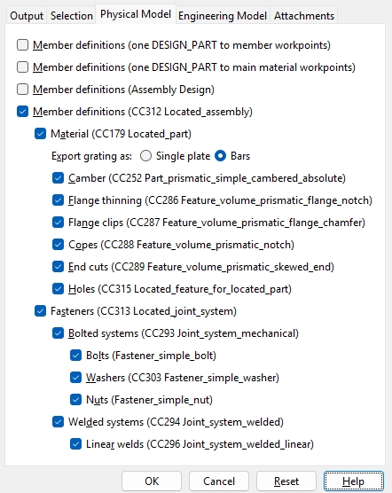
Physical Model
The physical 3D model from your current Job is exported to a CIS2 Part 21 file as entities. The same parts in a Job may be exported to a CIS2 file as different entities, or as the same entities with different characteristics. The options under this tab let you select which physical entities you want to include in the Part 21 file. The conformance class ( CC ) and/or name of the entity ( name_of_entity ) are placed in parenthesis for most selection options on this window. The name of the entity will help you to more easily reference the entity in the Part 21 file. The conformance class is a reference to volume 5 of the CIS2 standards ( Conformance Requirements ).
| Tip: The first three options under the Physical Model tab -- option 1 , option 2 and option 3 -- are mutually exclusive. If one of these options is checked ( |
Member definitions (one design_part to member workpoints): ![]() or
or ![]() . This is the first of three mutually exclusive export choices for creating a model to be used by Intergraph's Smart Plant 3D program (SP3D).
. This is the first of three mutually exclusive export choices for creating a model to be used by Intergraph's Smart Plant 3D program (SP3D).
|
This picture illustrates member workpoints. The exported model will be solid. It won't look like this. |
Member definitions (one design_part to main material workpoints): ![]() or
or ![]() . This is the second of three mutually exclusive export choices for creating a model to be used by Intergraph's Smart Plant 3D program (SP3D).
. This is the second of three mutually exclusive export choices for creating a model to be used by Intergraph's Smart Plant 3D program (SP3D).
|
This picture illustrates main material workpoints. The exported model will be solid. It won't look like this. |
Member definitions ( Assembly Design ): ![]() or
or ![]() . This is the third of three mutually exclusive export choices for creating a model to be used by Intergraph's Smart Plant 3D program (SP3D).
. This is the third of three mutually exclusive export choices for creating a model to be used by Intergraph's Smart Plant 3D program (SP3D).
Member definitions ( CC312 located_assembly ): ![]() or
or ![]() .
.
Material ( CC179 located_part ): ![]() or
or ![]() .
.
Export grating as: Single plate or Bars .
Select Single plate if you want grating material , grating tread material and bolted grating tread for stairs to be exported to the Part 21 file as a single plate.
Select Bars if you want grating material, grating tread material and bolted grating tread for stairs to be exported to the Part 21 file as a multiple entities consisting of bars.
Camber ( CC252 part_prismatic_simple_cambered_absolute ):
Flange thinning ( CC286 feature_volume_prismatic_flange_notch ):
Flange clips ( CC287 feature_volume_prismatic_flange_chamfer ):
Copes ( CC288 feature_volume_prismatic_notch ):
End cuts ( CC289 feature_volume_prismatic_skewed_end ):
Holes ( CC315 located_feature_for_located_part ):
Fasteners ( CC313 located_joint_system ): ![]() or
or ![]() .
.
Bolted systems ( CC293 joint_system_mechanical ):
Bolts ( fastener_simple_bolt ):
Washers ( CC303 fastener_simple_washer ):
Nuts ( fastener_simple_nut ):
Welded systems ( CC294 joint_system_welded ):
Linear welds ( CC296 joint_system_welded_linear ):
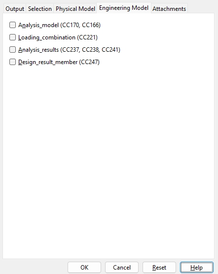
Engineering Model
Options under the Engineering Model tab allow various aspects of the SDS2 Engineering model of your current Job to be exported in a CIS2 file. The relevant conformance class ( CC ) is placed in parenthesis for the selection options on this window. The conformance class is a reference to volume 5 of the CIS2 standard ( Conformance Requirements ).
Analysis_model ( CC170, CC166 ): ![]() or
or ![]() . This applies to Jobs that have been Node Numbered in SDS2 Engineering.
. This applies to Jobs that have been Node Numbered in SDS2 Engineering.
Loading_combination ( CC221 ): ![]() or
or ![]() .
.
Analysis_results ( CC237, CC238, CC241 ): ![]() or
or ![]() .
.
Design_result_member ( CC247 ): ![]() or
or ![]() .
.
Attachments
Attach part drawings ( submaterial/gather sheets ): ![]() or
or ![]() .
.
Attach assembly drawings ( details/detail sheets ): ![]() or
or ![]() .
.
Attach placement drawings ( erection views ): ![]() or
or ![]() .
.
OK (or the Enter key) closes this screen and applies the settings.
Cancel (or the Esc key) closes this screen without saving any changes.
Reset undoes all changes made to this screen since you first opened it. The screen remains open.
1 . Click the Export Model icon, which is pictured above. The icon can be found on the Import/Export page > Model section.
Method 2: Click Export Model on the home screen. The command can be found on the Export tab in the 3D section. Skip step 2.
Alternative: Use the Find Tool by searching the command name and clicking the Export Model icon, which is pictured above.
Learn more about alternative methods for launching commands.
2 . The status line prompts Select members, and the Select - Pan - Menu mouse bindings become active. Select the member(s), then press Enter or right-click and select OK.
Alternative: Press the Esc key or right-click and select Cancel to end the command.
3 . The Export Model window opens.Select CIS2 as the Export file format. Set the Destination where you want the file to be sent. Directory outputs the file to a folder. Select Properties to open the CIS2 Export Properties window (as shown on the General Overview tab).
4 . Select OK to export the .stp file.
Alternative: Press the Esc key or select Cancel to end the command.