The Secondary Girt window
( Modeling > F2 > select " Secondary Girt ")
- To open this window:
- Add Secondary Girt (documentation is on another page)
- Double-click (any submaterial of the secondary girt with ' Default ' as the filter)
- Edit Member
- Edit by Piecemark (alternative to Edit Member )
- Edit by Member Number (alternative to Edit Member )
- Selection filter (useful tool that aids selection)
- Special indicator:


Red-colored highlighting identifies an entry that is invalid. You need to change that setting, or you will not be able to close this window using " OK ."
- Bottom row buttons (" Status " " Properties " " OK " ...)
- Warning! Don't make changes to the Rolled Section Material window that you can make on this window, Girt (Secondary) Edit . Most changes made to secondary girt material outside of this window will cause this member to be made "
 Graphical ," and those changes will be lost if you make this member not graphical ("
  Graphical ").
Also see :
- SECONDARY GIRTS (a downloadable HOW/2 .pdf file)
- Custom members (a secondary girt is a custom member)
- Rolled Section Material (window can set the Girt (Secondary)'s edit window to " Graphical ")
- Girt (to which you can add a secondary girt)
- Girt (Secondary) ( Home > Project Settings > Job )
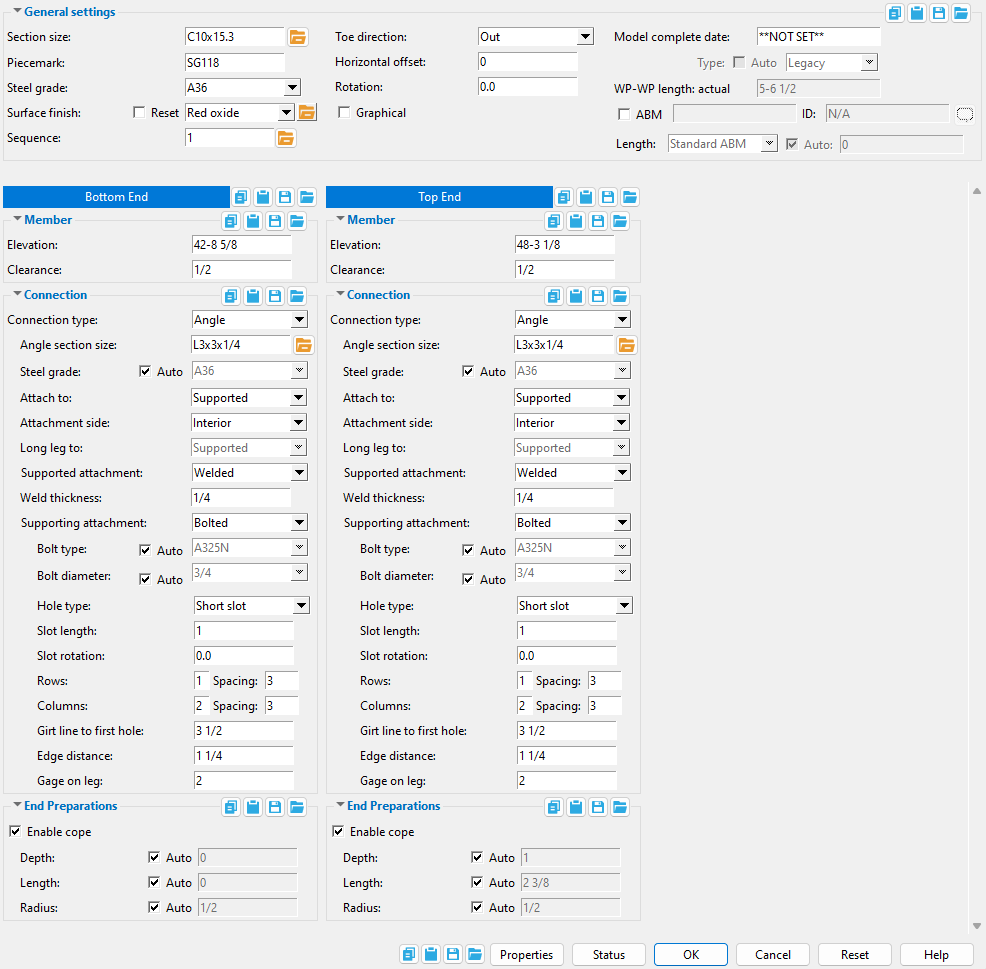
------  General settings ------
Section size: A section for C or cold formed C material that is listed in the local shape file . You must enter a section size in order to add a secondary girt .
C15x50

Since only " button.
To enter a section size: Either type in the section size that you want, or press the "file cabinet" browse button (
Note: Connections are only generated for channels and not for cold formed channels.
Piecemark: The member piecemark of the secondary girt
Typing in characters makes the piecemark a user piecemark .
To clear a user piecemark, or if you are adding a new secondary girt, leave this field blank. Piecemarking will assign a system piecemark when you press " OK ."
Steel grade: A36 or A572 or etc. This is the steel grade for the " Section size " entered above. The steel grades that you can select in this list box ( ![]() ) come from Home > Project Settings > Job > Channel Grades . Selecting ' Material ' as the selection filter and double-clicking the girt opens the Rolled Section Material window. You'll find that the " Steel grade " on that window matches the " Steel grade " that is entered here when " Graphical " is unchecked (
) come from Home > Project Settings > Job > Channel Grades . Selecting ' Material ' as the selection filter and double-clicking the girt opens the Rolled Section Material window. You'll find that the " Steel grade " on that window matches the " Steel grade " that is entered here when " Graphical " is unchecked ( ![]() ).
).
Sequence: Any sequence name from the Sequence Names setup list can be entered. Either type the sequence, or you can press the "file cabinet" browse button ( ![]() ) and double-click any sequence name that is on the list.
) and double-click any sequence name that is on the list.
Tip: If you want to add a new sequence so that it can be selected here, you should first increase the number of " Maximum sequences " that are available.
Rotation: A positive (+) or negative (-) number of degrees . This applies when the secondary girt has no supporting Girt on either end. Otherwise, if you add the secondary girt so that it frames to a girt, it will be automatically rotated perpendicular to the supporting girt, and this option will no longer be available if you later edit the secondary girt.
Assuming that you are looking down at the profile of the member from in a plan view. . .
' 0 ' degrees is the default position.
A ' positive number ' rotates the member that number of degrees counterclockwise from the default (0) position.
A ' negative (-) number ' rotates the member clockwise from the default (0) position.
' 90 ' rotates the miscellaneous member 90 degrees clockwise from the default (0) position.
' In ' ' Out '
' In ' points the toes of the channel toward the right side of the secondary girt. In other words, if the " Rotation " is ' 0 ' degrees, ' In ' points the toes to the near side in a plan view (or down if the " Rotation " is ' 90 ' degrees).
' Out ' points the toes of the channel away from the left side of the secondary girt. Since a plan view looks at members from the far side in (or from the bottom up for channels whose webs are vertical in a plan view), selecting ' Out ' points the toes to the far side if the " Rotation " is 0 degrees (or up if the " Rotation " is ' 90 ' degrees).
Horizontal offset: A distance no greater than 1'-0" (in the primary dimension " Units " or other units ) by which the secondary girt is offset from its workpoints in a plan view. A positive (+) distance corresponds to the direction of the X-axis of the supporting girt's member coordinate system. This applies only when the secondary girt frames into a supporting girt; otherwise, this distance is ignored.
|
|
Graphical : You should check this box when you no longer want the secondary girt to undergo Process and Create Solids . For example, when you are ready to begin manually modifying the member using Edit Material , material cutting operations, or etc. Click here for more information.
Model complete : You should enter a date to this field to prevent the secondary girt from being altered during the solids creation phase of Process and Create Solids . For example, when you have finished modifying the member. Click here for more information.
WP-WP length: actual: Read-only . The actual length of this member's workline (in the primary dimension " Units "). This " ![]() General settings " distance is calculated from the Z global coordinates of the member's work points .
General settings " distance is calculated from the Z global coordinates of the member's work points .
|
|
------ Member ------
Elevation: The elevation (in the primary dimension " Units " or other units ) of the work point at this end of the secondary girt.
To determine the end elevation on a secondary girt in the 3D model, use Construction Line Add or a similar tool, select EXPT as the Locate option, then snap the point location target to the work point at the end of the secondary girt. The Z coordinate reported in the X-Y-Z display tells you the elevation at the snapped-to exact point.
Tip: In most cases, this option is easier to use than using Model > Member > Move/Stretch to change the secondary girt's top- or bottom-end elevation.
Clearance: A distance from 0 to 2 inches, either measured parallel with the workline of the secondary girt from the work point for this end of the girt to the girt's main material. Or, if that end is proximate to a valid framing face, the distance is measured from that face to the girt's main material.
------ Connection ------
Connection type: Angle or Plain .
Select ' Plain ' when you do not want a connection designed on this end of the secondary girt. Even though this choice does not provide connection material, it still automatically copes and sets back a ' Plain end ' secondary girt when it frames to a supporting girt .
When ' Angle ' is selected, angle connection material is provided, and angle connection options are available .
Note: When ' Angle ' is selected, the secondary girt will be provided with connection material, even when it does not frame to another member. However, holes are not matched nor bolts added unless it frames to a supporting girt.
Angle connection options (apply to angle connection material) :
Angle section size: This is the size of the angle used in the connection.
To enter a section size: Either type in the section size that you want, or press the "file cabinet" browse button (
Note : While you can enter other section sizes than those of angles, the angle connection options on this window are valid only for angle section sizes. If you choose another section size -- for example, a WTee -- you may have to graphically alter the connection material to produce a suitable connection.
Steel Grade: Auto or A36 or A572 or etc . This is the steel grade for the " Angle section size " entered above
When ' Auto ' is checked (
When ' Auto ' is not checked (
), which come from Home > Project Settings > Job > Angle Grades .
Attach to: Supported or Supporting .
' Supported ' creates a clip angle connection that is shop attached to the supported secondary girt. If " Supported attachment " is set to ' Bolted ', the clip angle(s) shop bolt to the web of the secondary girt. If " Supported attachment " is ' Welded ', the clip angle(s) shop weld to it. The connection is considered to be a submaterial of the girt and will appear on details of the girt.
' Supporting ' specifies that the clip angle connection be shop attached to the supporting girt. If " Supporting attachment " is set to ' Bolted ', the outstanding legs of the clip angle(s) shop bolt to the supporting girt. If " Supporting attachment " is ' Welded ', the outstanding leg(s) shop weld to the supporting girt. The connection is considered to be a submaterial of the supporting girt and will appear on details of the girt.
Attachment side: Interior or Back . This is the side of the secondary girt that you want to attach the connection angle to.
|
|
' Interior ' shop or field attaches the angle leg to the secondary girt on the interior of the channel. Consequently, the angle leg to the supporting member faces in.
' Back ' attaches the angle leg to the secondary girt on the back of the channel.
Long leg to: Supported or Supporting . This applies if the " Angle section size " has legs of unequal lengths; in that case, you can decide which member the long leg is attached to.
|
|

' Supported ' shop or field attaches the long leg of the angle to the supported member; that is, the secondary girt.
' Supporting ' attaches the long leg of the angle to the supporting member.
Supported attachment: Welded or Bolted . When the " Connection type " is ' Angle ', this is the connection method by which the angle is field or shop attached to the secondary girt.
' Welded ' creates a connection that welds to the supported girt (that is, the secondary girt). If " Attach to " is ' Supported ', the connection material shop welds to the supported girt. If " Attached to " is ' Supporting ', the connection material field welds to the secondary girt.
' Bolted ' creates a connection that bolts to the supported girt (that is, the secondary girt). If " Attach to " is ' Supported ', the connection material is shop bolted to the supported girt. If " Attach to " is ' Supporting ', the connection material is field bolted to the secondary girt.
Supporting attachment: Welded or Bolted . When the secondary girt frames to a supporting member, this is the connection method by which the angle is field or shop attached to it.
' Welded ' creates a connection that welds to the supporting member (girt). If " Attach to " is ' Supporting ', the connection material shop welds to the supporting girt. If " Attached to " is ' Supported ', the connection material field welds to the supporting girt.
' Bolted ' creates a connection that bolts to the supporting member (girt). If " Attach to " is ' Supporting ', the connection material is shop bolted to the supporting girt. If " Attach to " is ' Supported ', the connection material is field bolted to the supporting girt.
Weld thickness: A distance (in the primary dimension " Units " or other units ) that indicates the size of the fillet weld attaching an angle leg to the secondary girt or to any supporting members. This applies wherever that leg's attachment method (" Supported ... " or " Supporting attachment ") method is ' Welded '. This sets the " Weld size " on the Weld Edit window in Modeling as well as the " Weld size " for the weld symbol on the girt detail.
The following apply to angle legs whose attachment method (" Supported ... " or " Supporting attachment ") is ' Bolted '.
Bolt type: A325 or A307 , etc. This is the type of bolt used for fastening an angle leg to a secondary girt or to any supporting girts. This applies wherever that leg's " Supported ... " or the " Supporting attachment " method is ' Bolted '. The types that listed in this list box (
Bolt diameter: The diameter of bolts for an angle leg. The diameters that are listed in this list box (
Hole type: Standard Round or Short Slot or Oversized Round or Long Slot or User Slot #1 or User Slot #2 . This is the type of hole for a leg of an angle.

Tip: Select the " Bolt diameter " before selecting ' Short slot ' option. That way, an appropriate " Slot length " can be automatically entered.
Setup: When a ' User slot #1 ' or ' User slot #2 ' is the selected " Hole type ," you can set the slot length you want applied to them on the User Slot Lengths window.
Slot length: A distance . This applies when the " Hole type " is a ' Slot .... ' A length is automatically entered when you choose a ' Short ... ' or ' Long slot ', but is disabled ( grayed out) when the hole is a " User slot.. .." The slot length, when automatically entered, depends on the " Hole type " and on the " Bolt diameter ."
Slot rotation: A positive or negative (-) number . This is available when the " Hole type " is a ' ...Slot ', and controls the rotation of the slot about its center.
Rows: 1 or 2 . The number of rows of bolts on an angle leg.
Row spacing: The center-to-center vertical distance between rows of holes.
row = " Row spacing " Columns: 1 or 2 . The number of columns of bolts on an angle.
Column spacing: The center-to-center horizontal distance between columns of holes.
col = " Column spacing " Girt line to first hole: This is the horizontal distance from the secondary girt member line to the location of the first bolt row on the angle.
gl1 = " Girt line to first hole " Edge distance: This is the horizontal distance edge distance from the edge of the angle to the nearest bolt column. This affects both edges of the angle equally.
ed = " Edge Distance " Gage on leg: This is the gage used for the connection on that leg measured from the heel of the angle.
gol = " Gage on leg "
------ End Preparations ------
Enable cope: ![]() or
or ![]() . This enables connection design to automatically generate copes. You can, however, override the default values with values that you enter here, in this window.
. This enables connection design to automatically generate copes. You can, however, override the default values with values that you enter here, in this window.
If this box is checked (
If this box is not checked (
Depth: Auto or a distance . This applies when " Enable cope " is checked ( ![]() ).
).
When ' Auto ' is checked (
When ' Auto ' is not checked (
Length: Auto or a distance . This applies when " Enable cope " is checked ( ![]() ).
).
When ' Auto ' is checked (
When ' Auto ' is not checked (
Radius: Auto or a distance . This applies when " Enable cope " is checked ( ![]() ).
).
When ' Auto ' is checked (
When ' Auto ' is not checked (
![]()
![]()
![]()
![]()
![]()
![]()
![]() ( form buttons ) are named " Copy " " Paste " " Save " and " Load ."
( form buttons ) are named " Copy " " Paste " " Save " and " Load ."
When form buttons are embedded in the headers for individual leaves on a Girt (Secondary) Edit window, the buttons apply only to the settings that are contained in that leaf.
Click here for more information about how form buttons work.
"Properties" opens the Edit Properties window, on which you can make entries to custom properties . If, at the time it was created, your current Job was set to use a legacy flavor, the window that opens is named Custom Properties , not Edit Properties .
The Edit Properties window can also be used to read "
Tip: Model > Member > Properties is an alternative to this button. It opens the Edit Properties window without your first having to open a member edit window.
" Status " opens the Member Status Review window, which can give you additional information about this secondary girt, and which you can use to enter status information.
"OK" (or the Enter key) closes this window and saves the settings on it.
.Red-colored highlighting identifies an entry that is invalid. You need to change that setting, or you will not be able to close this window using " OK ." The " Piecemark " that is shown, if it is a system piecemark, may change after you press " OK ." If there is no " Piecemark " shown, a system member piecemark will be assigned after you press " OK ."
Solids on " OK ": If the appropriate choice is made to User and Site Options > Modeling > " Automatically process after modeling operation ," then the member will automatically be regenerated ( Create Solids will take place) after your press " OK ." Otherwise, you will have to manually Process and Create Solids in order for changes you made on this window to be fully updated in the 3D model.
"Cancel" (or the Esc key) closes this window without changing (or adding) the girt you are editing (or adding).
"Reset" undoes any changes made since you first opened this window. That is to say, " Reset " populates this window with the settings that were originally entered to it when you first opened the window. The window remains open.

