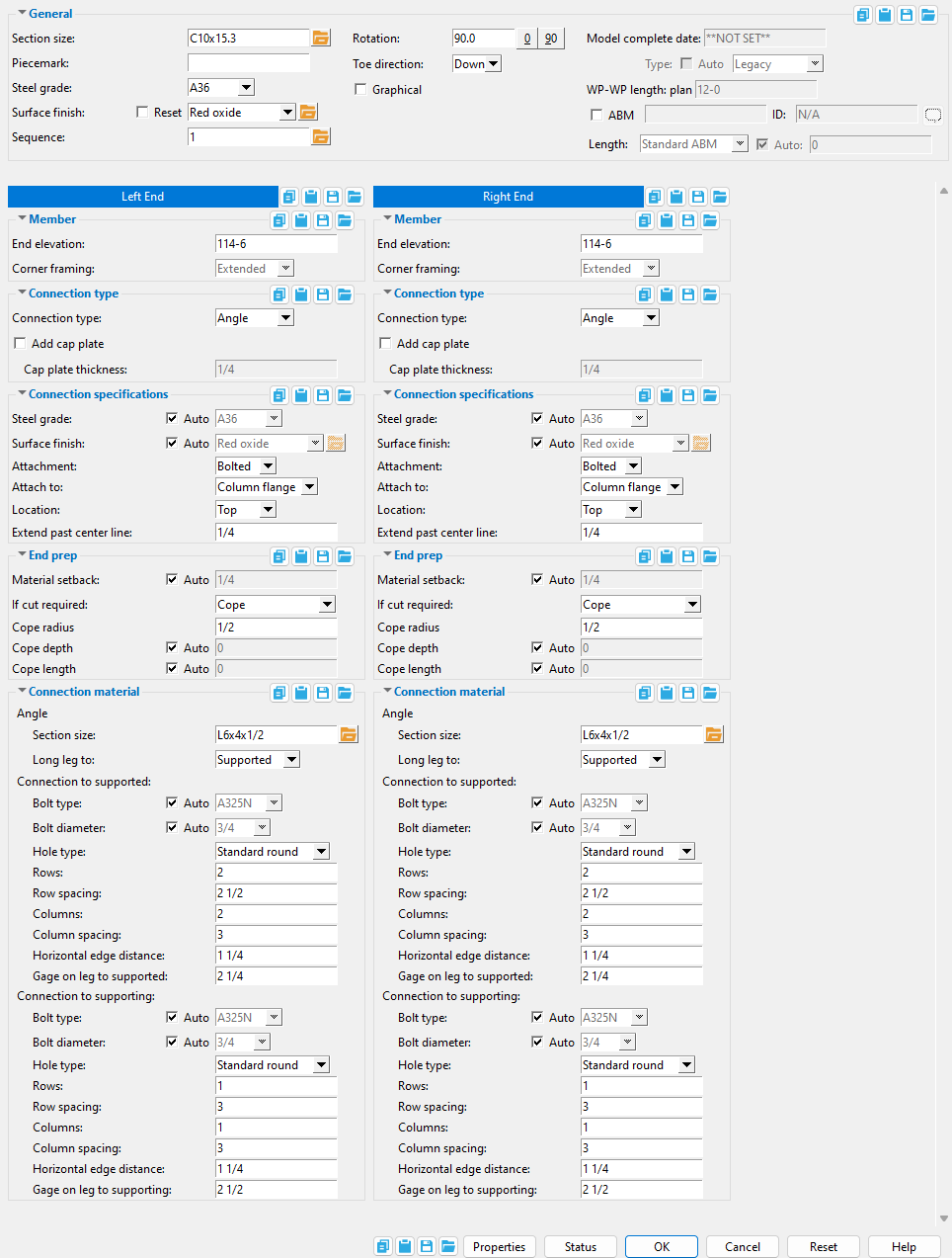
 The Girt Edit window ( Modeling > F2 >
  Misc Steel > select " Girt ")
- To open this window:
- Add Girt (documentation is on this page)
- Double-click (any submaterial of the girt with ' Default ' as the filter)
- Edit Member
- Edit by Piecemark (alternative to Edit Member )
- Edit by Member Number (alternative to Edit Member )
- Selection filter (useful tool that aids selection)
- Special indicator:


Red-colored highlighting identifies an entry that is invalid. You need to change that setting, or you will not be able to close this window using " OK ."
- Bottom row buttons (" Status " " Properties " " OK " ...)
- Warning! Don't make changes to the Rolled Section Material window that you can make on this window, Girt Edit . Most changes made to girt material outside of this window will cause this member to be made " Graphical ," and those changes will be lost if you make this member not graphical ("
 Graphical "). For this reason, you should clean up the girt using Model > Material tools only after you are certain that you will make no more changes on this window.
Also see :
- New/2 2018: Girts (YouTube) (
 )
)
- Custom members (topic)
- Secondary Girt
- Sag Rod
------  General settings ------
Section size: A section for wide flange or C or cold formed C or cold formed Z material that is listed in the local shape file . You must enter a section size in order to add a girt .
C15x50

This selection dialog opens when you press the button. Since "
To enter a section size: You can type in the section size that you want, or you can press the "file cabinet" browse button (
Piecemark: The member piecemark of the girt
Typing in characters makes the piecemark a user piecemark .
To clear a user piecemark, or if you are adding a new girt, leave this field blank. Piecemarking will assign a system piecemark when you press " OK ."
Steel grade : This is the steel grade for the " Section size " entered above. Selecting ' Material ' as the selection filter and double-clicking the girt opens the Rolled Section Material window. You'll find that the " Steel grade " on that window matches the " Steel grade " that is entered here when " Graphical " is unchecked ( ![]() ).
).
Sequence: Any sequence name from the Sequence Names setup list can be entered. Either type the sequence, or you can press the "file cabinet" browse button ( ![]() ) and double-click any sequence name that is on the list.
) and double-click any sequence name that is on the list.
Tip: If you want to add a new sequence so that it can be selected here, you should first increase the number of " Maximum sequences " that are available.
Rotation: A positive (+) or negative (-) number of degrees . The member is rotated around its member line. ' 90 ' degrees is the default when you first add a girt in a plan view, and is the rotation at which the girt's web is parallel with the work plan of that plan view.
Assuming that you are looking at the profile of the member from the end opposite to its origin . . .
' 0 ' degrees positions the member 90 degrees counterclockwise from the default position (90).
A ' positive number ' rotates the member that number of degrees counterclockwise from the zero position.
A ' negative (-) number ' rotates the member clockwise from the zero position.
' -90 ' rotates the miscellaneous member 90 degrees clockwise from the zero position.
Toe direction: Up or Down . This applies when the " Section size " is a wide flange or C or cold formed C or cold formed Z.
' Up '
' Down '
In a plan view, ' Up ' points the toes of the channel up if the " Rotation " is ' 90 ' degrees. If the " Rotation " is ' 0 ' degrees and the girt was input from the left to the right or the bottom to the top of the view, ' Up ' points the toes of the channel toward the far side in a plan view.
In a plan view, ' Down ' points the toes of the channel down if the " Rotation " is ' 90 ' degrees. If the " Rotation " is ' 0 ' degrees and the girt was input from the left to the right or the bottom to the top of the view, ' Down ' points the toes to the near side in a plan view.
Graphical : You should check this box when you no longer want the girt to undergo Process and Create Solids . For example, when you are ready to begin manually modifying the member using Edit Material , material cutting operations, or etc. Click here for more information.
Model complete : You should enter a date to this field to prevent the girt from being altered during the solids creation phase of Process and Create Solids . For example, when you have finished modifying the member. Click here for more information.
WP-WP length: plan: Read-only . This tells you the work point-to-work point distance (in the primary dimension " Units ") spanned by this purlin's work line in a plan view, ignoring elevation.. This " ![]() General settings " distance is calculated from the X and Y (but not Z) global coordinates of the purlin's work points .
General settings " distance is calculated from the X and Y (but not Z) global coordinates of the purlin's work points .
|
|
------ ![]() Member ------
Member ------
End elevation: The elevation (in the primary dimension " Units " or other units ) of the work point at this end of the girt.
To determine the end elevation on a girt in the 3D model, use Construction Line Add or a similar tool, select EXPT as the Locate option, then snap the point location target to the work point at the end of the girt. The Z coordinate reported in the X-Y-Z display tells you the elevation at the snapped-to exact point.
Tip: You will find it easier in most cases to use this option instead of Model > Member > Move/Stretch to change its top- or bottom-end elevation.
Corner framing: Extended or Shortened . This applies when the end of the girt is proximate to the end of another girt -- that is, when there is a corner condition -- and when these girts frame to a supporting member. When no such condition exists, this option is disabled -- that is, grayed out.
When ' Extended ' is chosen and " Material setback " is set to "
When ' Shortened ' is chosen and " Material setback " is set to "
Note: ' Material setback ' should be set to "
------ ![]() Connection type ------
Connection type ------
Connection type: Angle or Plate or W Tee or Plain end . This applies when the girt frames to a supporting member, such as a column. Otherwise, no connection material will be provided.
When ' Angle ' is selected, angle connection material is provided and appropriate connection options are made available .
When ' Plate ' is selected, plate connection material is provided and appropriate connection options are made available .
When ' W Tee ' is selected, W Tee connection material is provided and appropriate options are made available .
Select ' Plain ' when you do not want a connection designed on this end of the secondary girt.
Note: When ' Angle ' is selected, the secondary girt will be provided with connection material, even when it does not frame to another member. However, holes are not matched nor are bolts added unless the angle frames to a supporting girt.
Add cap plate: ![]() or
or ![]() . This adds a cap plate to the end of a C channel girt when it frames to a supporting member, such as a column.
. This adds a cap plate to the end of a C channel girt when it frames to a supporting member, such as a column.
|
|
Cap plate thickness: The thickness of the cap plate material (in the primary dimension " Units " or other units or the gage ). The girt's main material is set back by this thickness to accommodate the plate, so that the exterior face of the plate is always placed at the " Material setback " distance.
------ Connection specifications ------
( for angles, plates, and W Tees )
Steel grade: Auto or A36 or A572-42 or etc . This is the steel grade for the connection material for the chosen " Connection type ."
'
'
) that come from the appropriate Steel Grade s window for the chosen " Connection type ."
Surface finish: None or Sandblasted or Red oxide or Yellow zinc or Gray oxide or Blued steel or Galvanized or Duplex Coating or Undefined 1 or Undefined 2 or Undefined 3 or Red oxide 2 or Any user added surface finish. This affects the colors of 'Solid ' members on erection views in the Drawing Editor . This also sets the color when "Output material color " is set to 'Surface finish ' for a VRML Export or a DWG/DXF Export . The "Color " ( not "Surface finish ") sets the color of this material in Modeling .
| sand blasted | red oxide | yellow zinc | user surface finish 1 |
| gray oxide | blued steel | galvanized | user surface finish 2 |
To assign a different surface finish, you can drop-down the current surface finish and select the one you want, or you can press the "file cabinet" browse button (
) and double-click any surface finish that is on the list.
Auto ![]() or
or ![]() .
.
If this box is checked (
If the box is not checked (
Location: Top or Bottom . This is the side of the girt to which the connection material is field attached.
|
|
------ Connection specifications ------
( for angles )
Attachment: Welded or Bolted . When the girt frames to a supporting column, this is the connection method by which the angle is attached to it.
' Welded ' creates a connection that shop welds to the supporting member.
' Bolted ' creates a connection that is shop bolted to the supporting member.
Note: You cannot choose ' Bolted ' when " Attach to " is ' Column toe '.
Attach to: Column flange or Column toe . When the girt frames to a supporting column, this is the part of the column to which the angle is shop attached.
|
|

Note: You cannot choose ' Column toe ' when the " Attachment " method is ' Bolted '.
Extend past interior toe: When " Attach to " is ' Column toe ', this is the distance (in the primary dimension " Units " or other units ) by which the angle extends past the flanges of the column at each toe.
|
|
Extend past center line: When " Attach to " is ' Column flange ', this is the distance (in the primary dimension " Units " or other units ) by which the angle length extends past the center line of the column.
|
|
------ End prep ------
Material setback: Auto or a distance (in the primary dimension " Units " or other units ), measured parallel with the workline of the secondary girt from the work point for this end of the girt to the girt's main material, or to the face of the cap plate when " ![]() Add cap plate " is checked.
Add cap plate " is checked.
|
sb = " Material setback " |
'
'
If cut required: Cope or Cut flange flush or None . Documentation in progress
' Cope ' designs, if required, copes to prevent the girt from infringing the supporting member.
' Cut flange flush ' cuts the girt, if required, to prevent it from infringing the supporting member.
' None ' does not cut or cope the girt to prevent it from infringing the supporting member.
Cope radius: A distance (in the primary dimension " Units " or other units ). This is the radius of the cope that is applied when " If cut required " is ' Cope '.
|
Cope depth: Auto or a distance . This applies when " If cut required " is ' Cope '.
|
'
'
Cope length: Auto or a distance . This applies when " If cut required " is ' Cope '.
|
'
'
Flange cut near side: Auto or a distance . This applies when " If cut required " is ' Cut flange flush ' or ' None '. Documentation in progress
'
'
Flange cut far side: Auto or a distance . This applies when " If cut required " is ' Cut flange flush ' or ' None '. Documentation in progress
'
'
------ ![]() Connection material ------
Connection material ------
(for angles, plates, and W Tees)
Section size: This is the size of the ' Angle ' or ' W Tee ' if either are chosen as the " Connection type ."
To enter a section size: Either type in the section size that you want, or press the "file cabinet" browse button (
Note: While you can enter other section sizes than those of angles, the connection options in the
Add weld: ![]() or
or ![]() . This applies when the " Connection type " is ' Plate ' or ' W Tee ', or to ' Angle ' when its " Attachment " is ' Welded '.
. This applies when the " Connection type " is ' Plate ' or ' W Tee ', or to ' Angle ' when its " Attachment " is ' Welded '.
When " Add weld " is checked (
When this option is not checked (
Weld size: The weld size (in the primary dimension " Units " or other units ) for shop welding the connection material to the supporting member. This applies when the " Connection type " is ' Plate ' or ' W Tee ', or to ' Angle ' when its " Attachment " is ' Welded '.
Connection to supported :
Bolt type: Auto or A325N or A307 , etc. This is the type of bolt used for field fastening an angle leg, a plate, or a W tee flange to the girt.
'
'
Bolt diameter: The diameter of bolts for the angle leg that connects to the girt. The bolt diameter entered here, together with the " Hole type " sets the diameter of holes in the angle leg.
'
'
Hole type: Standard Round or Short Slot or Oversized Round or Long Slot or User Slot #1 or User Slot #2 . This is the type of hole for a leg of the angle leg that connects to the girt.

Setup: When a ' User slot #1 ' or ' User slot #2 ' is the selected " Hole type ," you can set the slot length you want applied to them on the User Slot Lengths window.
Slot length: A distance . This applies when the " Hole type " is a long slot or short slot. A length is automatically for a ' Short slot ' or ' Long slot '. The slot length, when automatically entered, depends on the " Hole type " and on the " Bolt diameter ."
Note: This option is disabled -- that is, grayed out -- when the " Hole type " is ' User slot #1 ' or ' User slot #2 '. Instead, set the slot length you want applied to them on the User Slot Lengths window.
Slot rotation: A positive or negative (-) number . This is available when the " Hole type " is a long slot or short slot. It rotates the slot about its center.
Rows: The number of rows of bolts attaching the connection material to the girt.
Row spacing: The distance between rows of bolts when the number of " Rows " attaching the connection material to the girt is greater than ' 1 '.
| rs = " Row spacing " | |||
|
|
|
|
|
Connection type =
' Angle ' |
Connection type =
' Plate ' |
Connection type =
' W Tee ' |
|
Columns: The number of columns of bolts attaching the connection material to the girt. When the " Connection type " is ' W Tee , ' this is the number of bolt columns on each flange; for example, entering ' 2 ' designs two columns on each flange for a total of four columns on the W tee.
Column spacing: The distance between columns of bolts when the number of " Columns " attaching the connection material to the girt is greater than ' 1 '.
| cs = " Column spacing " | |||
|
|
|
|
|
Connection type =
' Angle ' |
Connection type =
' Plate ' |
Connection type =
' W Tee ' |
|
Girt line to first hole: The distance from the edge of the outer girt to the center of the nearest column of bolts when the " Connection type " is ' Angle ', or to the first row of bolts when the " Connection type " is ' Plate ' or ' W Tee '.
| grt1 = " Girt line to first hole " | ||
|
|
|
|
Connection type =
' Angle ' |
Connection type =
' Plate ' |
Connection type =
' W Tee ' |
Vertical edge distance: The distance from the outer edge girt to the edge of the connection material closest to the girt edge to the nearest column of bolts.
| ved = " Vertical edge distance " | ||
|
|
|
|
Connection type =
' Angle ' |
Connection type =
' Plate ' |
Connection type =
' W Tee ' |
------ ![]() Connection material ------
Connection material ------
( for angles )
Long leg to: Supported or Supporting . This applies when the chosen angle " Section size " has legs of unequal length.
' Supported ' attaches the long leg to the supported member; that is, to the girt.
' Supporting ' attaches the long leg to the supporting column.
Gage on leg to supported: The distance from the heel of the angle to the center of the nearest row of bolts.
|
gol = " Gage on leg to supported " |
Connection to supporting :
These options apply when the 'Attachment ' method to supporting is ' Bolted '.
Bolt type: Auto or A325N or A307 , etc. This is the type of bolt used for fastening an angle leg to the supporting column..
'
'
Bolt diameter: Auto or the diameter of bolts for the angle leg that connects to the supporting column. The bolt diameter entered here, together with the " Hole type " sets the diameter of holes in the angle leg.
'
'
Hole type: Standard Round or Short Slot or Oversized Round or Long Slot or User Slot #1 or User Slot #2 . This is the type of hole for a leg of an angle leg that connects to the supporting column.
Setup: When a ' User slot #1 ' or ' User slot #2 ' is the selected " Hole type ," you can set the slot length you want applied to them on the User Slot Lengths window.
Slot length: A distance . This applies when the " Hole type " is a long slot or short slot. A length is automatically entered when you first choose a ' Short slot ' or ' Long slot ' hole type. The slot length, when automatically entered, depends on the " Hole type " and on the " Bolt diameter ."
Note 1: Once a slot length is entered -- either by the user or automatically -- changing the " Bolt diameter " does not automatically update the slot length for the remainder of your current Modeling session.
Note 2: This option is disabled -- that is, grayed out -- when the " Hole type " is ' User slot #1 ' or ' User slot #2 '. Instead, set the slot length you want applied to them on the User Slot Lengths window.
Slot rotation: A positive or negative (-) number . This is available when the " Hole type " is a long slot or short slot. It rotates the slot about its center.
Rows: The number of rows of bolts attaching the angle to the supporting column.
Row spacing: The distance between rows of bolts when the number of " Rows " attaching the angle to the supporting column is greater than ' 1 '.
|
Columns: The number of columns of bolts on each flange that attach the angle to the supporting column; for example, entering ' 2 ' creates two bolt columns on each flange of the supporting column, for a total of four bolt columns.
Column spacing: The distance between columns of bolts when the number of " Columns " attaching the angle to the supporting column is greater than ' 1 '.
|
Horizontal to first hole: The distance from the center line of the supporting column to the center of the first column of bolts.
|
Gage on leg to supporting: The distance from the heel of the angle to the center of the first row of bolts.
|
------ ![]() Connection material ------
Connection material ------
(for plates)
Pl ate thickness: When the " Connection type " is ' Plate ', this is the thickness of the plate material (in the primary dimension " Units " or other units or the gage ).
Horizontal edge distance: The horizontal distance from the edge of the plate to the center of the nearest column of bolts.
|
hed = " Horizontal edge distance " |
Note: When the plate connects to the web of a supporting W flange shape, the plate may extend to the column's flanges. In that case, the entry for " Horizontal edge distance " is ignored.
Horizontal to first hole: A positive or negative (-) horizontal distance from the centerline of the supporting member to the center of the first column of bolts. The first bolt column is the one nearest to the end of the girt. A positive distance moves that bolt column horizontally away from the girt end. This option is available only when the edge, and not the end, of the girt frames to a supporting column.
|
ht1 = " Horizontal to first hole " A negative distance is shown here. |
![]()
![]()
![]()
![]()
![]()
![]()
![]() ( form buttons ) are named " Copy " " Paste " " Save " and " Load ."
( form buttons ) are named " Copy " " Paste " " Save " and " Load ."
When form buttons are embedded in the headers for individual leaves on a Girt (Secondary) Edit window, the buttons apply only to the settings that are contained in that leaf.
Click here for more information about how form buttons work.
"Properties" opens the Edit Properties window, on which you can make entries to custom properties . If, at the time it was created, your current Job was set to use a legacy flavor, the window that opens is named Custom Properties , not Edit Properties .
The Edit Properties window can also be used to read "
Tip: Model > Member > Properties is an alternative to this button. It opens the Edit Properties window without your first having to open a member edit window.
" Status " opens the Member Status Review window, which can give you additional information about this secondary girt, and which you can use to enter status information.
"OK" (or the Enter key) closes this window and saves the settings on it.
Red-colored highlighting identifies an entry that is invalid. You need to change that setting, or you will not be able to close this window using " OK ." The " Piecemark " that is shown, if it is a system piecemark, may change after you press " OK ." If there is no " Piecemark " shown, a system member piecemark will be assigned after you press " OK ."
Solids on "OK": If the appropriate choice is made to User and Site Options > Modeling > " Automatically process after modeling operation ," then the member will automatically be regenerated ( Create Solids will take place) after your press " OK ." Otherwise, you will have to manually Process and Create Solids in order for changes you made on this window to be fully updated in the 3D model.
"Cancel" (or the Esc key) closes this window without changing (or adding) the girt you are editing (or adding).
"Reset" undoes any changes made since you first opened this window. That is to say, " Reset " populates this window with the settings that were originally entered to it when you first opened the window. The window remains open.

