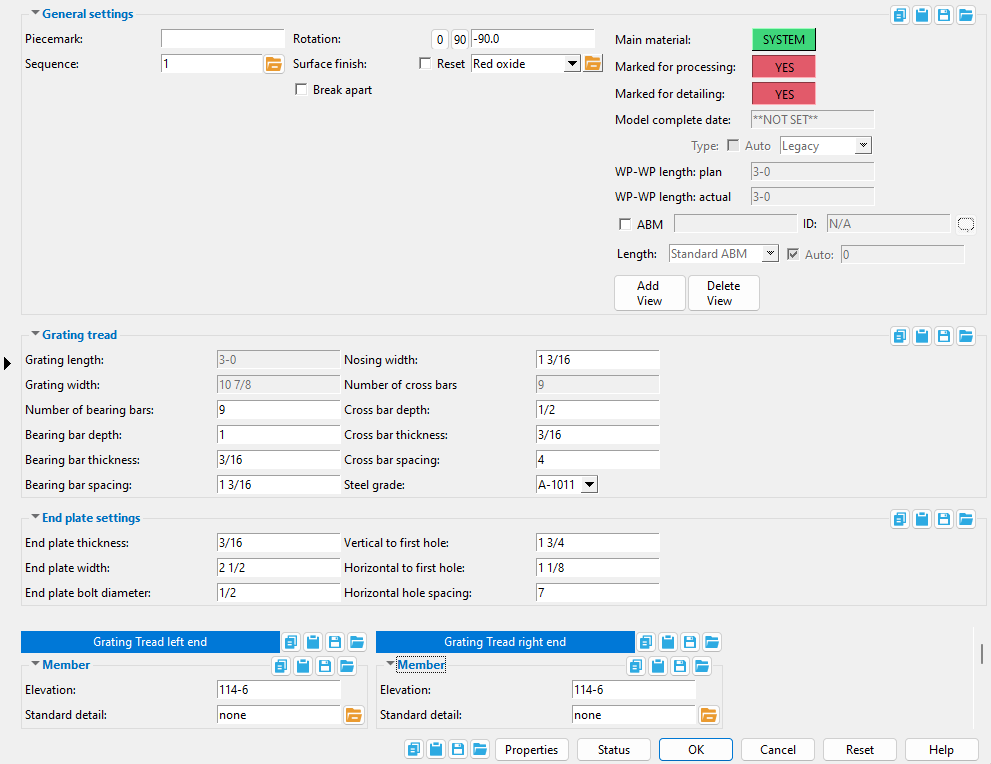
Grate Tread Edit window
( Modeling > F2 > "  Misc steel " > " Grate Tread ")
Selecting " Grate Tread "as the " Miscellaneous steel " type adds a custom member with grating tread material to a 3D model.
The Grate Tread custom member is a superior alternative to " Miscellaneous -- Grate Tread ."
The edit window of this member features material and member options on the same window.
Its " General settings " include " Break apart " and " Rotation ," which are not available for the legacy miscellaneous member.


The " OK " button is disabled (grayed out) to indicate a validation error. Hover the " OK " button with your mouse pointer to get a listing of settings you need to change on this window. When all settings are valid, the " OK " button is enabled. 
Red-colored highlighting identifies an entry that is invalid. You need to change that setting, or you will not be able to close this window using " OK ."
Also see :
- Material Types (topic)
- Miscellaneous member types (the complete list)
- Custom members (a grate tread miscellaneous member is a custom member)
- Grating Tread Material (window can set Grate Tread Edit 's " Main Material " to ' USER ')
- Miscellaneous members versus legacy miscellaneous members (topic)
- Surfaces Connection (a custom component you can add to a miscellaneous member)
Add Grating Tread :
1 . A grating tread miscellaneous member can be properly located and rotated even in an isometric view. Before adding the member, be aware of the following:
2 . To add a grating tread miscellaneous member (in Modeling ):
Alternative 1 : Press F2 > check the box for "
Alternative 2 : Choose Model > Member > Prompt for Member Type > check the box for "
Two work points are required to lay out a grating tread. The work points of a grating tread align with the top of the nosing of the tread.
3 . Locate - Repeat - Return mouse bindings become active, and you are prompted to locate the grating tread member's work points. Two work points are required to lay out grating. Generally, grating is placed in a plan view at a " Rotation " of ' -90 ' degrees (the default).
|
|
|
bindings |
3a : Select the appropriate Locate option.
3b : Left-click ( Locate ) at two different on-screen positions to define the member line between those two points. The first work point you enter when you add the tread defines the left end of the member. Both points are represented as exact points after step 4, when the member is actually generated in the model.

The first point that you locate is identified by an origin symbol . The origin symbol also tells you which end is the member's left end. If you Model > Member > Isolate > ... a grating miscellaneous member, you will find that the member's MAIN VIEW shows the member's origin symbol (
) to be to your left. This is true for any miscellaneous member -- even if the origin symbol for the member is to your right in a plan view. The MAIN VIEW in member isolation directly correlates to the main view of the miscellaneous member's detail.
Best practice when adding a miscellaneous member in a plan view is to input the member from left to right or from bottom to top. That way, when you add a grid line from left to right, the near side of the member, as determined by the location of its left end , will be the side looking toward the bottom or toward the right of the screen.
4 . The Grating Tread Edit window opens. On it are settings for the grating material you are adding.
4a : Be sure to make correct entries to " Number of bearing bars ," " Bearing bar depth ," " Bearing bar thickness ," " Bearing bar spacing ," " Nosing width ," " Cross bar depth ," " Cross bar thickness ," " Cross bar spacing ," and " End plate settings ."
4b : Press the " OK " button at the bottom of the window to apply your settings and close this window.
Note: The default settings on this window are those of the last grating tread miscellaneous member added or edited in this session of Modeling . Even if all you do is double-click a grating tread member and press " OK " on its edit window, its settings become the defaults for the next-added grating tread miscellaneous member. You therefore only need to make changes to those settings which are different for this member.
5 . If User and Site Options > Modeling > " Process after modeling operation " is ' Process and create solids ', the new grating tread will have automatically undergone all phases of Process and Create Solids and will show up in a solid form . If that option is ' Process ' or ' Do nothing ', then the member line of the tread you just added shows up on screen in stick form , and you will have to Process > Process and Create Solids in order to have the member piecemarked and able to be displayed in a solid form. Do one (1) of the following:
|
|
|
bindings |
Alternative 1 : Move the mouse pointer (
) and middle-click ( Repeat ) to lay out a grating tread just like the last one beginning at the point where the point location target (
) is at. The X, Y global axes location of the repeated plate will begin from the located repeat point (where the target is at). The plate's Z location and other settings will be that of the last-added or last-edited grating tread.
Alternative 2 : Follow these instructions beginning with step 3 to add a grating tread with different settings than the one you just laid out.
Alternative 3 : Right-click ( Return ) if you are done adding grating tread.
------ Grating tread ------
Grating length: This is a read-only information field that tells you the actual length (in the primary dimension " Units " or other units ) spanned by the grating tread's member line.
Note: Length is added to/subtracted from the end of the grating that is opposite to the left end . Changing this distance adjusts the " Number of cross bars " while keeping their thickness and spacing the same.
The following can be used to track the choice made here when " Main material " is ' SYSTEM ':
Grating width: This is a read-only information field that tells you the width (in the primary dimension " Units ") of the grating.
Note: Grating width is calculated based on the following formula: grating tread width = [( number of bearing bars - 1)( bearing bar spacing )] + bearing bar thickness + nosing width . This means that if you change the " Number of bearing bars " or " Bearing bar spacing " or " Bearing bar thickness " or " Nosing width ," the grating tread width will be recalculated.
The following can track the choice made here when " Main material " is ' SYSTEM ':
Number of bearing bars: The total quantity ( 1 or 2 or 3 or ...) of bars that are parallel with the grating tread's member line.
Note: Changing the number of bearing bars that is entered here changes the " Grating width ." Each of these bars will be slightly shorter than the " Grating length " is long.
The following can reliably track the choice made here when " Main material " is ' SYSTEM ':
Report Writer: XXXXXX . NumberOfStringersInGrate
Advanced Selection: NumberOfStringersInGrate
Bearing bar depth: The distance (in the primary dimension " Units " or other units ) between the top and bottom edges of any one bearing bar. All bearing bars will be this same depth. Depth is measured perpendicular to the member line of the grating tread.
The following can be used to show the choice made here when " Main material " is ' SYSTEM ':
Report Writer: XXXXXX . BearingBarWidth
Advanced Selection: BearingBarWidth
Bearing bar thickness: The thickness (in the primary dimension " Units " or other units ) of any one bearing bar. All bearing bars will be this same thickness.
Note: Changing the bearing bar thickness that is entered here also changes the " Grating width ."
Fabricator Setup: Add bearing bar thickness to grating tread description ( Member Detailing Settings )
The following can be used to reveal the choice made here when " Main material " is ' SYSTEM ':
Report Writer: XXXXXX . BearingBarThickness
Advanced Selection: BearingBarThickness
Bearing bar spacing: The spacing (in the primary dimension " Units " or other units ) between any one bearing bar and the next bearing bar plus the thickness of the one bearing bar.
Note: Changing the bearing bar spacing that is entered here also changes the " Grating width ."
The following can read the choice made here when " Main material " is ' SYSTEM ':
Report Writer: XXXXXX . BearingBarSpacing
Advanced Selection: BearingBarSpacing
Nosing width: The width (in the primary dimension " Units " or other units ) of the nosing plate. This dimension is perpendicular to the member line and measured from the member line edge of the grating tread to the nearest edge of the nearest bearing bar.
Note: Changing the width of nosing that is entered here also changes the " Grating width ."
The following can be used to track the choice made here when " Main material " is ' SYSTEM ':
Report Writer: XXXXXX . NosingWidth
Advanced Selection: NosingWidth
Number of cross bars: Read-only . This tells you the number of bars ( 1 or 2 or 3 or ...) that are perpendicular to the grating tread's member line, not including the end plates.
Note: To change the number of cross bars, you need to adjust the " Grating tread length " or change the " Cross bar spacing ."
Cross bar depth: The distance (in the primary dimension " Units " or other units ) measured perpendicular to the member line of the grating tread between the top and bottom edges of any one cross bar. All cross bars will be the depth you specify here.
The following can reveal the choice made here when " Main material " is ' SYSTEM ':
Report Writer: XXXXXX . CrossBarWidth
Cross bar thickness: The thickness (in the primary dimension " Units " or other units ) of any one cross bar. All cross bars are this same thickness.
The following can track the choice made here when " Main material " is ' SYSTEM ':
Report Writer: XXXXXX . CrossBarThickness
Cross bar spacing: The spacing (in the primary dimension " Units " or other units ) between any one cross bar cross bar and the next cross bar plus the thickness of the one cross bar.
Note: Changing the cross bar spacing may cause the " Number of cross bars " to be recalculated. For instance, if you were to increase the cross bar spacing, the " Number of cross bars " might decrease since the " Grating tread length " would remain the same.
The following can read and output the choice made here when " Main material " is ' SYSTEM ':
Report Writer: XXXXXX . CrossBarSpacing
Steel grade: The steel grades that you can select in this list box ( ![]() ) come from Home > Project Settings > Job > Grating Grades . Since connection design does not reference the steel grade applied to a grating tread, there are no Fy and Fu values on that setup window.
) come from Home > Project Settings > Job > Grating Grades . Since connection design does not reference the steel grade applied to a grating tread, there are no Fy and Fu values on that setup window.
The following can track the choice made here when " Main material " is ' SYSTEM ':
Bill of material: Steel Grade
Status Display: Member status > Steel grade
Advanced Selection: MaterialGrade
Parametric module: MaterialGrade
|
|
------ End plate settings ------
| SDS2 grating tread has two end plates. Settings under this heading operate on both of these end plates. |
End plate thickness: The thickness (in the primary dimension " Units " or other units ) of the grating tread's end plates.
Note: Changing the end plate thickness may cause the " Number of cross bars " to be recalculated.
End plate width: The distance (in the primary dimension " Units " or other units ) from the member line that was established when work points were laid out for this grating tread to the bottom edge of the end plate.
Note: End plate width is measured perpendicular to the work line of the grating tread. The length of the grating tread's end plate is determined by the " Grating width ."
End plate bolt diameter: The diameter (inches or mm) of the shanks of the bolts to be inserted into the end plate holes.
Note: Standard round holes are used in the end plate. The diameter of these holes is calculated from the " End plate bolt diameter " entered here per Table J3.3 or Table J3.3M ( AISC Thirteenth Edition , p. 16.1-105).
Vertical to first hole: The vertical distance (in the primary dimension " Units " or other units ) from the top edge of the end plate to the center of the first hole. The first hole is the hole that is nearest to the member line of the grating tread.
Exception: This distance will not be perfectly vertical if the top of the grating tread is not in the plane of a plan view.
Horizontal to first hole: The horizontal distance (in the primary dimension " Units " or other units ) from the nosing edge of the end plate to the first hole. Grating tread nosing is along the member line that was established when work points were laid out for the grating tread.
Exception: This distance will not be perfectly horizontal if the top of the grating tread is not in the plane of a plan view.
Horizontal hole spacing: The horizontal distance (in the primary dimension " Units " or other units ) from the center of one hole to the center of the next hole.
Note: The horizontal hole spacing entered here also determines the number of holes on the end plate. If grating width - (2)( horizontal to first hole ) > (2)(horizontal hole spacing), then three (or more) holes are added. If grating width - (2)( horizontal to first hole ) > (3)(horizontal hole spacing), then four (or more) holes are added.
|
------ Member ------
End elevation: The elevation (in the primary dimension " Units " or other units ) of the work point at this end of the grating tread. For a non-sloping tread, both the left and right end elevations are the same. When you add the grating tread, its work points are placed in your current view's reference elevation until you change their elevations here, on this window. The work points of a grating tread align with the top of the nosing of the tread.
| A grating tread has four exact points . You can reset the elevation of the two along its member line by changing the member's left- and/or right-end " End elevation ." |
|
To determine the end elevation on a grating tread in the 3D model, use Construction Line Add or a similar tool, select EXPT as the Locate option, then snap the point location target to the work point at the end of the member. The Z coordinate reported in the X-Y-Z display tells you the elevation at the snapped-to exact point.
Tip: You should use this option instead of rotating a grating tread member's material to change its left- or right-end elevation. For complex situations, you can Model > Member > Move/Stretch one or the other of its work points.
Standard detail: None or a standard detail name . To apply a standard detail, you can type in the file name of the drawing (if you know it), or press the "file cabinet" browse button ( ![]() ) and double-click any job standard detail or global standard detail that is on the list.
) and double-click any job standard detail or global standard detail that is on the list.
If ' none ' is entered here, then no standard detail will be applied on this end of the miscellaneous member when it is automatically detailed .
If a ' standard detail name ' is entered here, the next time you auto detail this miscellaneous member, the reference point of the standard detail will align with the input work point on this end of the member, and the standard detail's bill of material will be combined with the member's bill of material. The detail is placed on a layer that is named after the standard detail plus a "_L" or "_R" suffix.

