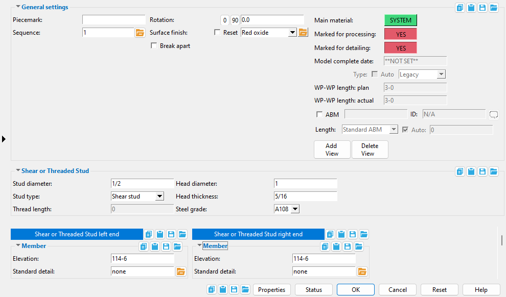
Shear or Threaded Stud Edit window
( Modeling > F2 > "  Misc steel " > " Shear Stud ")
Selecting " Shear or Threaded Stud " as the " Miscellaneous steel " type adds a custom member with shear or threaded stud material to a 3D model.
The Shear or Threaded Stud custom member is a superior alternative to " Miscellaneous -- Shear or Threaded Stud ."
The edit window of this member features material and member options on the same window.
Its " General settings " include " Break apart " and " Rotation ," which are not available for the legacy miscellaneous member.


The " OK " button is disabled (grayed out) to indicate a validation error. Hover the " OK " button with your mouse pointer to get a listing of settings you need to change on this window. When all settings are valid, the " OK " button is enabled. 
Red-colored highlighting identifies an entry that is invalid. You need to change that setting, or you will not be able to close this window using " OK ."
Also see :
- Material Types (topic)
- Miscellaneous member types (the complete list)
- Custom members (a shear stud miscellaneous member is a custom member)
- Shear or Threaded Stud Material (window can set Shear or Threaded Stud Edit's " Main Material " to ' USER ')
- Miscellaneous members versus legacy miscellaneous members (topic)
Add a shear or threaded stud :
1 . A shear stud miscellaneous member can be properly located and rotated even in an isometric view. Before adding the member, be aware of the following:
2 . To add a shear or threaded stud miscellaneous member (in Modeling ):
Alternative 1 : Press F2 > check the box for "
Alternative 2 : Choose Model > Member > Prompt for Member Type > check the box for "
3 . Locate - Repeat - Return mouse bindings become active, and you are prompted to locate the stud's work points. Two work points are required to lay out a shear or threaded stud member. The following steps assume that you are adding a perfectly vertical stud in a plan view -- you can enter studs in other view types without entering a point location offset.
|
|
|
bindings |
3a : Select the appropriate Locate option. You may want to add intersection construction lines so that there is an INCL point for locating the same point twice.
3b : Left-click ( Locate ) at an on-screen position to locate the first work point, which defines the left end of the member. Because this stud will be perfectly vertical, this point will be directly below the second work point.
3c : Enter a " Z+ " or " Z= " value in the Offset Controls toolbar item. The difference between this value and the previous Z value will define the actual length of the stud.
3d : Left-click ( Locate ) the same on-screen position you located in step 3a to define the member line between that point and the first point you entered. The second point location also defines the head of the stud. Both points are represented as exact points after step 4, when the member is actually generated in the model.

The first point that you locate is identified by an origin symbol . The origin symbol also tells you which end is the member's left end.
The following illustration shows the how these points may be oriented for a vertical stud in a plan view.
If you Model > Member > Isolate > ... a shear or threaded stud miscellaneous member, you will find that the member's MAIN VIEW shows the member's origin symbol (
) to be to your left. This is true for any miscellaneous member -- even if the origin symbol for the member is to your right in a plan view. The MAIN VIEW in member isolation directly correlates to the main view of the miscellaneous member's detail.
Best practice when adding a miscellaneous member in a plan view is to input the member from left to right or from bottom to top. That way, when you add a grid line from left to right, the near side of the member, as determined by the location of its left end , will be the side looking toward the bottom or toward the right of the screen.
4 . The Shear or Threaded Stud Edit window opens. On it are settings for the stud that you are adding.
4a : Enter a " Stud Diameter "
4b : Choose a " Stud Type "
4c : If a headless stud is desired, enter a " Head Diameter " that is equal than the " Stud Diameter " you entered in step 4a. Otherwise, enter a greater diameter.
4d ( optional ): You can change the length of the stud if you change the " Elevation " of the left or right end in the Left/Right End Settings portion of the Shear or Threaded Stud Material window. The left end is the end associated with the first point you located in step 3b. The right end is associated with the head of the stud. For a perfectly vertical stud, the difference between these elevations will define its actual length .
4e : Press the " OK " button at the bottom of the window to apply your settings and close this window.
Note: The default settings on this window are those of the last shear or threaded stud miscellaneous member added or edited in this session of Modeling . Even if all you do is double-click a stud member and press " OK " on its edit window, its settings become the defaults for the next-added stud miscellaneous member. You therefore only need to make changes to those settings which are different for this member.
5 . If User and Site Options > Modeling > " Process after modeling operation " is ' Process and create solids ', the new section will have automatically undergone all phases of Process and Create Solids and will show up in a solid form . If that option is ' Process ' or ' Do nothing ', then the member line of the rolled section you just added shows up on screen in stick form , and you will have to Process > Process and Create Solids in order to have the member piecemarked and able to be displayed in a solid form. Do one (1) of the following:
|
|
|
bindings |
Alternative 1 : Move the mouse pointer (
) and middle-click ( Repeat ) to lay out a stud just like the last one beginning at the point where the point location target (
) is at. The X, Y global axes location of the repeated member will begin from the located repeat point (where the target is at). The section's Z location and other settings will be that of the last-added or last-edited stud.
Alternative 2 : Follow these instructions beginning with step 3 to add a stud with different settings than the one you just laid out.
Alternative 3 : Right-click ( Return ) if you are done adding shear or threaded studs.
Tip: Copy Member is an excellent alternative to the Repeat mouse binding. For example, you can apply the ' Linear ' copy function to a stud you have centered on a beam flange to create a row of equally spaced studs along the beam's length.
------ Shear or Threaded Stud ------
Stud diameter: The rod diameter (in the primary dimension " Units " or other units ) of the shear stud or threaded stud.
|
d = diameter |
The following can be used to track the choice made here when " Main material " is ' SYSTEM ':
Report Writer: XXXXX . Diameter
Advanced Selection: Diameter
Parametric module: DiameterAlso see: Changing the shear stud's diameter causes the " Weight of item " on the material's General Information window to be recalculated.
Stud type: Shear stud or Threaded stud .
' Shear stud ' may be used to model non-threaded studs that are field or shop welded, usually to beams, to bond concrete to steel to ensure composite action. A " Head diameter " and " Head thickness " may be specified for a shear stud. The prefix set for " Shear Stud " in Home > Project Settings > Fabricator > Piecemarking > Member and Material Piecemarking > the " Prefixes " tab is added to the " Description " on the Modeling material's General Information window and in the Drawing Editor 's member bill of material. For example, a shear stud with a " Stud diameter " of '1/2' inch is automatically described as WS 1/2 when ' WS ' is the " Description " in Fabricator Setup .
' Threaded stud ' may be used to model threaded rods or sag rods or anchor bolts. You can add threads to the stud by specifying a " Thread length ." The prefix set for " Threaded Stud " in Member and Material Piecemarking > the " Prefixes " tab is added to the " Description " on the Modeling material's General Information window and in the Drawing Editor 's member bill of material. For example, a threaded stud with a " Stud diameter " of '1/2' inch is automatically described as THD STUD 1/2 when ' THD STUD ' is the " Description " in Fabricator Setup .
Thread length: The distance (in the primary dimension " Units " or other units ) from the right end of the member's main material to where you want the threaded area to end. The right end is the end opposite to the origin reference point symbol that is shown at the beginning of a Rotate Material operation. The following illustration shows how Modeling represents the threaded area when the round bar is displayed in solid opaque form. This does not affect auto detailing . The " Stud type " must be ' Threaded stud ' to get threads on the stud.
tl = thread length
 |
Head diameter: The diameter (in the primary dimension " Units " or other units ) of the shear stud's head. The " Stud type " must be ' Shear stud ' to get a head on the stud.
|
hd = head diameter |
Tip: Making this the same as the " Shear stud diameter " results in a shear stud without a head.
The following can be used to track the choice made here when " Main material " is ' SYSTEM ':
Report Writer: XXXXX . HeadDiameter
Advanced Selection: HeadDiameter
Parametric module: HeadDiameter
Head thickness: The distance (in the primary dimension " Units " or other units ) between the top of the head of the shear stud and the lower lip of the head of the shear stud. The " Stud type " must be ' Shear stud ' to get a head on the stud.
| ht = head thickness |
|
Tip: Enter a " Head thickness " of ' 0 ' if you want a shear stud without a head.
The following can be used to track the choice made here when " Main material " is ' SYSTEM ':
Report Writer: XXXXX . HeadThickness
Advanced Selection: HeadThickness
Parametric module: HeadThickness
Steel grade: A108 or A493 or etc. This is the grade of steel for the shear stud or threaded stud whose settings are defined on this window.
Setup: If the grade of steel you want is not shown in the list box (
), you can use Home > Project Settings > Job > Shear and Threaded Stud Grades to add it to this list.
Tip: Changing " Steel grade " does not cause the member's main material to be regenerated. This means that, if you change this setting only, material operations such as a Cut on Plane may, optionally, be preserved.
The following can be used to track the choice made here when " Main material " is ' SYSTEM ':
Advanced Selection: MaterialGrade
Parametric module: MaterialGrade
|
|
|
----- Member ------
End elevation: The elevation (in the primary dimension " Units " or other units ) of the work point at this end of the stud. The right end elevation will always be greater than the left end elevation when the stud is vertical. When you add the stud, its work points are placed in your current view's reference elevation until you change their elevations here, on this window. Work points are aligned with the center of the stud.
| A stud has two exact points , whose elevation you can change by changing the member's left- and/or right-end " End elevation ." |
|
To discover the end elevation of a stud in the 3D model , use Construction Line Add or a similar tool, select EXPT as the Locate option, then snap the point location target to the work point at the end of the member. The Z coordinate reported in the X-Y-Z display tells you the elevation at the snapped-to exact point.
Tip: For complex situations, you can Model > Member > Move/Stretch one or the other of its work points to change the elevation of the stud's head or its tip.
Standard detail: None or a standard detail name . To apply a standard detail, you can type in the file name of the drawing (if you know it), or press the "file cabinet" browse button ( ![]() ) and double-click any job standard detail or global standard detail that is on the list.
) and double-click any job standard detail or global standard detail that is on the list.
If ' none ' is entered here, then no standard detail will be applied on this end of the miscellaneous member when it is automatically detailed .
If a ' standard detail name ' is entered here, the next time you auto detail this miscellaneous member, the reference point of the standard detail will align with the input work point on this end of the member, and the standard detail's bill of material will be combined with the member's bill of material. The detail is placed on a layer that is named after the standard detail plus a "_L" or "_R" suffix.

