 Add Beam Stiffeners at Column ( Modeling )
Tool summary :
One way to edit the Beam Stiffeners component is to open the Column Edit window. Another way is to double-click a stiffener or stiffener weld with the " Selection filter " set to ' Default ' or ' All ' or ' Custom Components ''.
VIDEO 
The Beam Stiffeners at Column custom component is used to add stiffeners to a beam that is under the column that the custom component belongs to.
- See, on this help page, to edit or delete the custom component .
Also see :
- Modeling (where custom components can be added)
- Custom components (topic)
- Component Plugin Setup ( Home > Project Settings > Job > Component Plugin Defaults > )
- Copy Component (to copy the component to another column, its stiffeners to a beam under/over that column)
- Move Component (to move the component to another column, its stiffeners to a beam under/over that column)
- Explode Component (to reduce the component to its constituent materials and welds)
- Component Selection Tool (to search for custom components of a selected type)
- Model Tree (to find custom components and select them for deletion, editing, etc.)
To edit or delete the custom component :
Selecting any material or weld that is part of the component selects the entire component when the " Selection filter " is set to ' Default ' or ' All ' or ' Custom Components '',
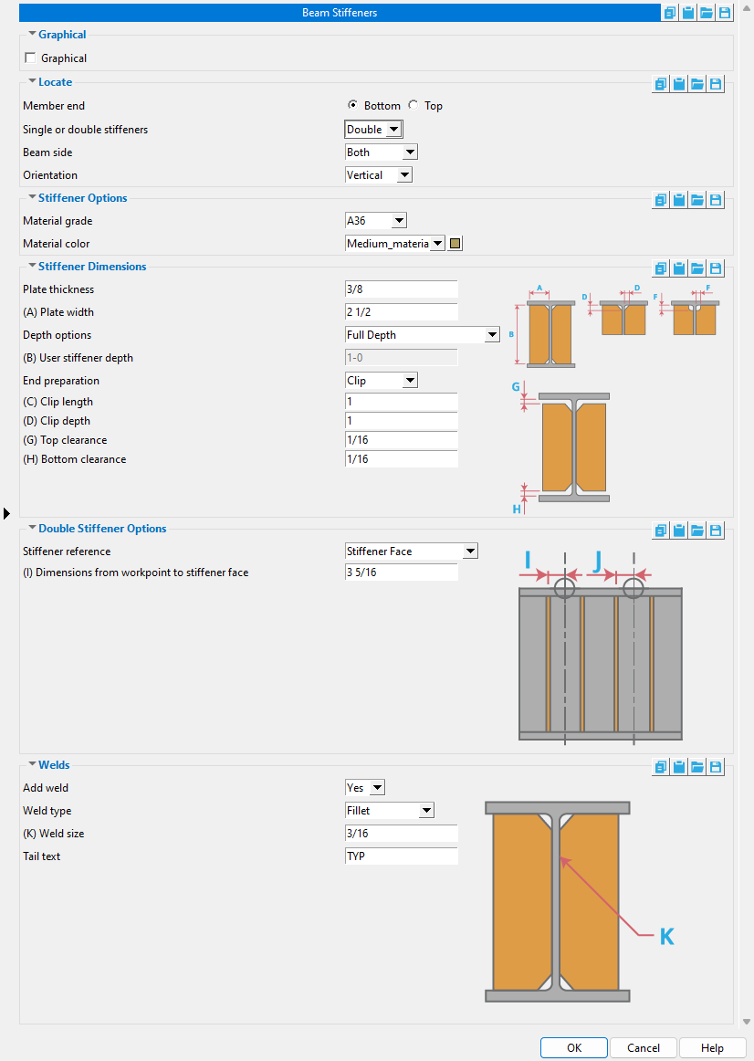
Beam Stiffeners at Column custom component settings :
![]() Graphical ----------------------------------------------------------------------
Graphical ----------------------------------------------------------------------
Graphical : ![]() or
or ![]() .
.
- A Beam Stiffeners at Column component is automatically set to "
 Graphical " whenever you make graphical changes to any of its materials or welds. For example, when you Edit Material or perform a material cutting operation on a Beam Stiffeners at Column material. This stops the component from being changed during Process and Create Solids . Click here for more information.
- Instead of allowing the component to be made " Graphical ." you may wish to Explode Component .
![]() Locate ----------------------------------------------------------------------
Locate ----------------------------------------------------------------------
|
|
' Bottom ' sets the stiffeners to be generated on the beam that is below the column that the Beam Stiffeners at Column custom component is a " Component " of.
' Top ' sets the stiffeners to be generated on the beam that is above the column that the Beam Stiffeners at Column custom component is a " Component " of.
Single or double stiffeners: Single or Double .
|
| To get examples like those shown above, you need to set the column " Member end " to ' Bottom ' since the beam stiffeners are below the column. |
' Single ' designates one stiffener (per beam side) which is centered at the work point of the column.
' Double ' designates two stiffeners per beam side. The stiffeners will be spaced evenly around the work point of the column based on the choice made to .
Beam side: Both or Near Side or Far Side .
|
| The examples shown above are all viewed from the beam's left end . |
' Both ' puts stiffeners on both the near side and far side of the beam's web.
' Near Side ' puts the stiffener(s) on the near side of the beam. The near side web of a beam is the main view that is shown on a beam detail. If you are looking at a beam web and the left end of that beam is to your left, then you are looking at the near side of the beam.
' Far Side ' puts the stiffener(s) on the far side of the beam.
Orientation: Normal or Vertical or Rotate .
|
|
' Normal ' orients the stiffener(s) normal to the beam. That is, the stiffeners will be perpendicular to the beam's flanges.
' Vertical ' orients the stiffener(s) vertically.
' Rotate ' lets you, the user, specify the rotation of the stiffener(s) by entering a number of degrees for the " Rotation about WP ."
![]() Stiffener Options ------------------------------------------------------------------
Stiffener Options ------------------------------------------------------------------
Material grade: A36 or A572 or etc. This is the grade of steel for the stiffener plate(s). This is also the " Steel grade " of the rectangular plate material that each stiffener plate is made of.
Setup: If the grade of steel you want is not shown on the list box (
), you can use Home > Project Settings > Job > Plate Grades to add it to the list.
Material color: A predefined color or a custom color . This sets the approximate color of the stiffener plates when the beam they are submaterials of is displayed in one of the three solid forms . This is also the " Color " of the rectangular plate material that each stiffener plate is made of.
The predefined colors are set up on the Predefined Colors window. The color swatch next to the list box (
Select ' Custom Color ' (last choice on the list) to launch your operating system's color picker and define any color you like.
![]() Stiffener Dimensions ------------------------------------------------------------
Stiffener Dimensions ------------------------------------------------------------
Plate thickness: The thickness of each of the stiffener plate(s) (in the primary dimension " Units " or other units ). This is also The " Material thickness " of the rectangular plate material that each stiffener plate is made of.
Plate width: The width of each of the stiffener plate(s) (in the primary dimension " Units " or other units ). This is also the " Material width " of the rectangular plate material that each stiffener plate is made of.
Depth options: Full depth or Top Flange Half Depth or Bottom Flange Half Depth or Top Flange Bottom K or Bottom Flange Top K or Top Flange User Depth or Bottom Flange User Depth . The stiffeners will be sized automatically based on the choice made here and on the " Depth " specified for the beam's section size in the local shape file .
' Full Depth ' extends the stiffeners to the top and bottom flanges of the beam minus the " Top clearance " and the " Bottom clearance ."
' Top Flange Half Depth ' extends the stiffeners from the top flange of the beam to the half-depth of the beam.
' Bottom Flange Half Depth ' extends the stiffeners from the bottom flange of the beam to the half-depth of the beam.
' Top Flange Bottom K ' extends the stiffeners from the top flange of the beam to the bottom k distance of the beam.
' Bottom Flange Top K ' extends the stiffeners from the top flange of the beam to the bottom k distance of the beam.
' Top Flange User Depth ' extends the stiffeners from the top flange of the beam to the "User stiffener depth" specified below.
' Bottom Flange User Depth ' extends the stiffeners from the bottom flange of the beam to the "User stiffener depth" specified below
User stiffener depth: The length of each of the stiffener plate(s) (in the primary dimension " Units " or other units ). This is also the " Order length " of the rectangular plate material that each stiffener plate is made of. This applies when ' Top Flange User Depth ' or ' Bottom Flange User Depth ' has been selected for " Depth options ."
End preparation: Clip or Cope or Fit exact .
' Clip ' applies a rectangular plate " Clip " operation to each stiffener. The " Clip length " dimension runs parallel with the length of the stiffener. The " Clip depth " dimension runs parallel with the width of the stiffener.
' Cope ' applies a rectangular plate " Cope " operation to each stiffener. The " Cope length " dimension runs parallel with the length of the stiffener. The " Cope depth " dimension runs parallel with the width of the stiffener.
' Fit exact ' precisely fits the contour of the stiffener to the contour of the beam web with a 1/16 inch setback.
Top clearance: The distance (in the primary dimension " Units " or other units ) between the top edge of each stiffener and the bottom face of the beam's top flange.
Bottom clearance: same as " Top clearance ," except that this is the distance between the bottom edge of each stiffener and the top face of the beam's bottom flange.
![]() Double Stiffener Options -----------------------------------------------------
Double Stiffener Options -----------------------------------------------------
Stiffener reference ( and spacing ): Stiffener Face or Stiffener Centerline .
' Stiffener Face ' lets you enter a " Dimension from workpoint to stiffener face ." The inside faces of each of the stiffeners will be that distance from the work line of the column.
' Stiffener Column ' lets you enter a " Dimension from workpoint to stiffener centerline ." The center of each stiffener will be that distance from the work line of the column.
![]() Welds -----------------------------------------------------------------------------------
Welds -----------------------------------------------------------------------------------
|
|
' Yes ' instructs Beam Stiffeners at Column to shop weld the stiffener(s) to the beam. 3D welds will appear in the model. After the beam is auto detailed ( Detail Members ), the stiffener welds will be represented on the beam's detail by a weld symbol .
' No ' instructs Beam Stiffeners at Column to not add welds.
Weld type: Fillet or Square groove or Bevel groove . This sets the " Weld type " on the Weld Edit window in Modeling as well as the " Weld type " for the weld symbol on the beam detail.
| symbol | name | weld used for... |
|
|
fillet | General welding of material. |
|
|
square groove | Butt joints of material 3/8" thick or less. |
|
|
bevel groove | General full penetration welding of material. |
Weld size: A distance (in the primary dimension " Units " or other units ) that indicates depth of preparation, size or strength of the weld. This sets the " Weld size " on the Weld Edit window in Modeling as well as the " Weld size " for the weld symbol on the beam detail.
Tail text: blank or a text string . This sets the " Supplementary tail text " on the Weld Edit window in Modeling as well as the " Supplementary tail text " for the weld symbol on the beam detail.
|
This weld symbol's tail text is TYP . |
If this field is left ' blank ', a tail is not drawn on the weld symbol.
If a ' string of characters ' is entered, a tail with that character string as the tail text is drawn on the weld symbol.

