Rolled Plate Edit window
( Modeling > F2 > "  Misc steel " > " Rolled Plate ")
Selecting " Rolled Plate " as the " Miscellaneous steel " type adds a custom member with rolled plate material to a 3D model.
The Rolled Plate custom member is a superior alternative to " Miscellaneous -- Rolled Plate ."
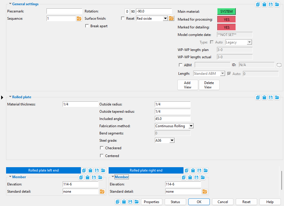
The edit window of this member features material and member options on the same window.
Its " General settings " include " Break apart " and " Rotation ," which are not available for the legacy miscellaneous member.


The " OK " button is disabled (grayed out) to indicate a validation error. Hover the " OK " button with your mouse pointer to get a listing of settings you need to change on this window. When all settings are valid, the " OK " button is enabled. 
Red-colored highlighting identifies an entry that is invalid. You need to change that setting, or you will not be able to close this window using " OK ."
Also see :
- Plates (topic)
- Miscellaneous member types (the complete list)
- Custom members (a rolled plate miscellaneous member is a custom member)
- Rolled Plate Material (window can set Rolled Plate Edit 's " Main Material " to ' USER ')
- Miscellaneous members versus legacy miscellaneous members (topic)
Add rolled plate :
1 . A rolled plate miscellaneous member can be properly located and rotated even in an isometric view. Before adding the member, be aware of the following:
- The key to ensuring that a miscellaneous member's material is properly oriented in the model is proper location of the member's work points and proper " Rotation " around the member line established by those work points. The member's material can also be " Centered " on the vertex of its outside radii with respect to the member line.
- Before adding a rolled plate miscellaneous member in Modeling , you should Open ( Ctrl + o ) a view that will facilitate the locating of the work points
- Work points for a perfectly vertical rolled plate can be located in an elevation view .
- Work points for a sloping rolled plate -- for example, a section whose member line follows the slope of a roof -- should be added in a view that is at the desired slope. To create such a view, you can use Navigate > Snap to Surface or View > Section View .
2 . To add a rolled plate miscellaneous member (in Modeling ):
Alternative 1 : Press F2 > check the box for "
Alternative 2 : Choose Model > Member > Prompt for Member Type > check the box for "
3 . Locate - Repeat - Return mouse bindings become active, and you are prompted to locate the rolled plate's work points. Two work points are required to lay out a rolled plate.
|
|
|
bindings |
3a : Select the appropriate Locate option.
3b : Left-click ( Locate ) at two different on-screen positions to define the member line between those two points. The first work point you enter when you add the rolled plate defines the left end of the member. Both points are represented as exact points after step 4, when the member is actually generated in the model.
When " Centered ," is checked (

The first point that you locate is identified by an origin symbol . The origin symbol also tells you which end is the member's left end. The following illustration shows the difference between locating the two points from left to right versus right to left.
If you Model > Member > Isolate > ... a rolled plate miscellaneous member, you will find that the member's MAIN VIEW shows the member's origin symbol (
) to be to your left. This is true for any miscellaneous member -- even if the origin symbol for the member is to your right in a plan view. The MAIN VIEW in member isolation directly correlates to the main view of the miscellaneous member's detail.
Best practice when adding a miscellaneous member in a plan view is to input the member from left to right or from bottom to top. That way, when you add a grid line from left to right, the near side of the member, as determined by the location of its left end , will be the side looking toward the bottom or toward the right of the screen.
4 . The Rolled Plate Edit window opens. On it are settings for the rolled plate that you are adding.
4a : The " Included angle " and " Outside radius " define the rolled plate's " Unrolled width ." Be sure to also define the " Material thickness ."
4b : Press the " OK " button at the bottom of the window to apply your settings and close this window.
Note: The default settings on this window are those of the last rolled plate miscellaneous member added or edited in this session of Modeling . Even if all you do is double-click a rolled plate member and press " OK " on its edit window, its settings become the defaults for the next-added rolled plate miscellaneous member. You therefore only need to make changes to those settings which are different for this member.
5 . If User and Site Options > Modeling > " Process after modeling operation " is ' Process and create solids ', the new plate will have automatically undergone all phases of Process and Create Solids and will show up in a solid form . If that option is ' Process ' or ' Do nothing ', then the member line of the rolled plate you just added shows up on screen in stick form , and you will have to Process > Process and Create Solids in order to have the member piecemarked and able to be displayed in a solid form. Do one (1) of the following:
|
|
|
bindings |
Alternative 1 : Move the mouse pointer (
) and middle-click ( Repeat ) to lay out a rolled plate just like the last one beginning at the point where the point location target (
) is at. The X, Y global axes location of the repeated plate will begin from the located repeat point (where the target is at). The plate's Z location and other settings will be that of the last-added or last-edited rolled plate.
Alternative 2 : Follow these instructions beginning with step 3 to add a rolled plate with different settings than the one you just laid out.
Alternative 3 : Right-click ( Return ) if you are done adding rolled plate.
------ Rolled plate ------
Material thickness: The thickness of this rolled plate (in the primary dimension " Units " or other units or the gage ). The thickness of a " Checkered " plate is measured exclusive of its raised pattern.
To enter gage plate: Type the ' gage number' followed by ' ga ' (example: ' 4ga ' is rewritten as ' 4GA ' when you Tab out of the field). Right-click tells you the stored thickness (based on industry standards), from which the weight of the gage plate is calculated. Allowable gages are any whole number from 3 to 38 . You can also enter an exact decimal thickness to get the gage (example: ' .1345 ' becomes ' 10GA ' when you Tab out of the field). The " Description " for a gage plate follows the format: ' plate prefix ' + ' numberGA ' + ' x ' + ' width ' (example: PL16GAx15 1/2 ).
Thickness precision : You can enter a plate " Material thickness " that is more precise than the " Dimension precision " that is set at Home > Project Settings > Fabricator > Detailing > Drawing Presentaton . For example, if you enter ' 5/32 ' and the " Dimension precision " is ' 1/16 ', the thickness of the plate will be ' 5/32 '. The thickness you enter will be reflected in the " Description " and will propagate to the bill of material, reports, etc. The setup option to " Round flat plate values " does not affect this. Be aware that the Ruler measures to whatever the " Dimension precision " is set to, which means that the plate's measured thickness may not exactly match its actual thickness.
The following can be used to track the choice made here when " Main material " is ' SYSTEM ':
Status Display: Material status > Material plate thickness
Report Writer: XXXXX . Thickness
Advanced Selection: Thickness
Parametric module: Thickness
Outside radius: The distance (in the primary dimension " Units " or other units ) from the outside corner the rolled plate to the center of an imaginary circle extrapolated from the outside edges of the rolled plate. This distance must be measured at the left end of the rolled plate if the " Outside tapered radius " results in a taper.
Visualizing the outside radius: Imagine you are looking at the end of the rolled plate where the first work point was located; you would see a cross-section of the width of the rolled plate. Extrapolate an arc from the outside curvature of the bend on the rolled plate, then measure the distance from either end of that arc to the center of the imaginary circle which that arc is a part of.
The following can report the choice made here when " Main material " is ' SYSTEM ':
Report Writer: XXXXX . RollOrBendRadius
Note: The rolled plate material's " Unrolled width " is calculated from the rolled plate's " Outside radius " and " Included angle ," So, when " Main material " is ' SYSTEM ', making a change to the " Outside radius " can directly affect the unrolled width of the rolled plate. In that case, these output the material's unrolled width setting that should match the choices made here and to the member's " Included angle :"
Report Writer: XXXXX . Width
Advanced Selection: Width
Parametric module: Width
Outside tapered radius: A distance (in the primary dimension " Units " or other units ) specifying the radius of the rolled plate from the end opposite to the left end of the rolled plate member.
The ' exact same distance ' as the " Outside radius " makes the rolled plate not tapered .
A ' distance ' other than that entered to " Outside radius " or ' 0 ' makes the rolled plate tapered. An entry of ' 0 ' to " Outside tapered radius " is ignored, and the rolled plate is not tapered. " Outside tapered radius " works the same way as " Outside radius ," except that this distance is measured from the end of the rolled plate opposite to the left end of the rolled plate member.
The following can reliably track the choice made here when " Main material " is ' SYSTEM ':
Report Writer: XXXXX . TaperRadius
Advanced Selection: TaperRadius
Parametric module: TaperRadius
Included angle: Any positive angle from .1 to 360 degrees.
This is the number of degrees of the circle that is taken up by the arc of the outside face of the rolled plate. (The radius of this arc is the " Outside radius ").
The following can reliably report the choice made here when " Main material " is ' SYSTEM ':
Report Writer: XXXXX . RolledOrBentAngle
Note: The rolled plate material's " Unrolled width " is calculated from the rolled plate's " Outside radius " and " Included angle ." So, when " Main material " is ' SYSTEM ', making a change to the " Included angle " can directly affect the unrolled width of the rolled plate. In that case, these output the material's unrolled width setting that should match the choices made here and to the member's " Outside radius :"
Report Writer: XXXXX . Width
Advanced Selection: Width
Parametric module: Width
Fabrication method: Continuous rolling or Segmented bending .
' Continuous rolling ' sets the curve of the rolled plate to be smooth, continuous and parabolic.
' Segmented bending ' causes the rolled plate to be a series of flat (not-curved) bend segments that together approximate a parabola. The number of segments is the number entered to " Bend segments ."
Bend segments: 0 or a quantity of segments of 3 to 400 .
' 0 ' (zero) produces the same result as " Continuous rolling ."
An entry of ' 3 or greater ' applies when " Segmented rolling " is selected. The more the segments, the smaller the bend angle between each segment, and the more closely the rolled plate approximates a continuous parabolic curve.
Steel grade: A36 or A572 or etc. This is the grade of steel of the rolled plate whose settings are defined on this window.
Setup: If the steel grade you want is not on the list box (
) for this field, you can use Home > Project Settings > Job > Plate Grades to add it to the list.
Tip: Changing the " Steel grade " does not cause the plate to be regenerated. This means that, if you change this setting only, material cut operations such as a Cut Layout may, optionally, be preserved.
The following can reliably track the choice made here when " Main material " is ' SYSTEM ':
Report Writer: MemberMaterial.Material.SubMaterial.MaterialGradeDescription
Advanced Selection: MaterialGrade
Parametric module: MaterialGrade
If this box is checked (
If the box is not checked (
), the rolled plate is considered to have a smooth near-side surface.
The following can accurately track the choice made here when " Main material " is ' SYSTEM ':
Report Writer: XXXXX . CheckeredPlatePattern
Advanced Selection: CheckeredPlatePattern
Parametric module: CheckeredPlatePattern
Centered: ![]() or
or ![]() . This option positions the rolled plate with respect to the member's left end.
. This option positions the rolled plate with respect to the member's left end.
If this box is checked (
If the box is not checked (
|
|
|
------ Member ------
End elevation: The elevation (in the primary dimension " Units " or other units ) of the work point at this end of the rolled plate. For a non-sloping plate, both the left and right end elevations are the same. When you add the rolled plate, its work points are placed in your current view's reference elevation until you change their elevations here, on this window.
| A rolled plate has two exact points , whose elevation you can change by changing the plate's left- and/or right-end " End elevation ." |
|
To determine the end elevation on a rolled plate in the 3D model, use Construction Line Add or a similar tool, select EXPT as the Locate option, then snap the point location target to the work point at the end of the member. The Z coordinate reported in the X-Y-Z display tells you the elevation at the snapped-to exact point.
Tip: You should use this option instead of rotating a rolled plate member's material to change its left- or right-end elevation. For complex situations, you can Model > Member > Move/Stretch one or the other of its work points.
Standard detail: None or a standard detail name . To apply a standard detail, you can type in the file name of the drawing (if you know it), or press the "file cabinet" browse button ( ![]() ) and double-click any job standard detail or global standard detail that is on the list.
) and double-click any job standard detail or global standard detail that is on the list.
If ' none ' is entered here, then no standard detail will be applied on this end of the miscellaneous member when it is automatically detailed .
If a ' standard detail name ' is entered here, the next time you auto detail this miscellaneous member, the reference point of the standard detail will align with the input work point on this end of the member, and the standard detail's bill of material will be combined with the member's bill of material. The detail is placed on a layer that is named after the standard detail plus a "_L" or "_R" suffix.

