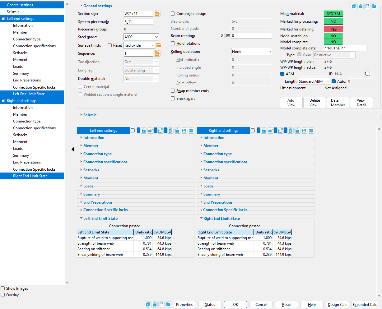
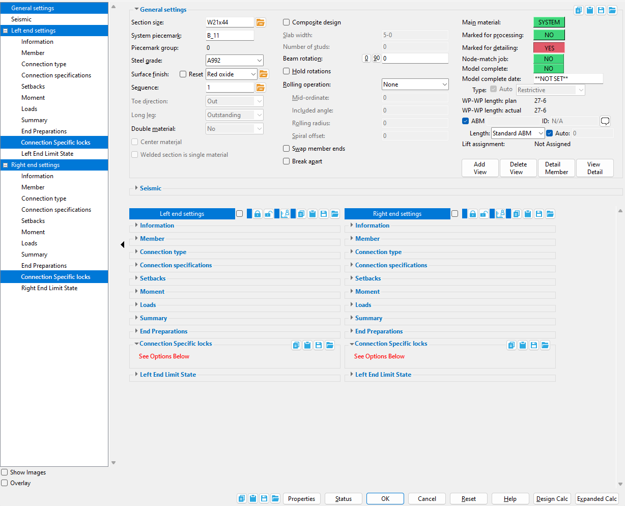
"  Show images " (when checked) displays drawings that depict the dimensions that are controlled by connection design locks .
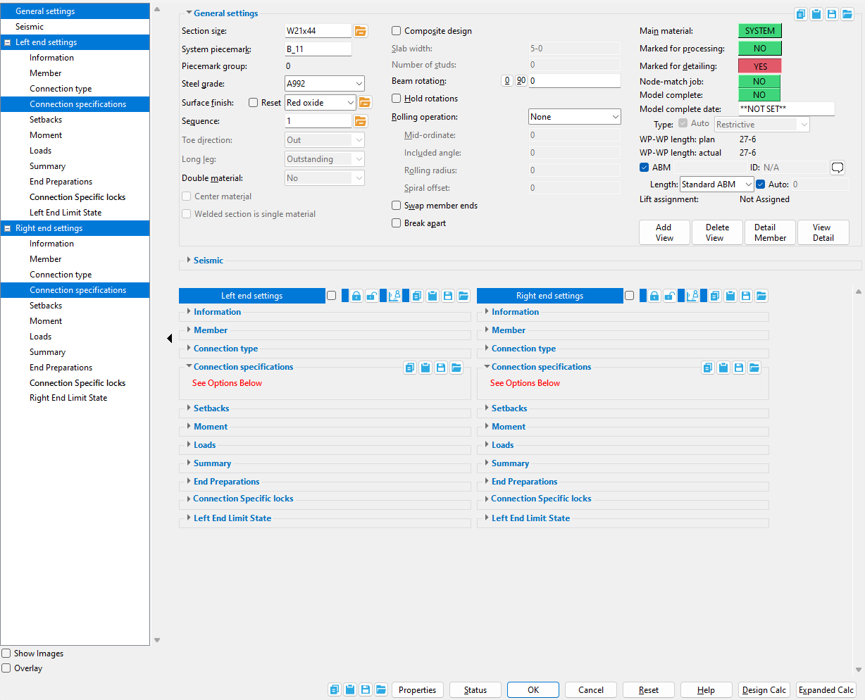
" Overlay " (when checked) displays one leaf at a time. When you select a leaf, either from the tree on the left or from inside the window itself, all other leaves collapse.
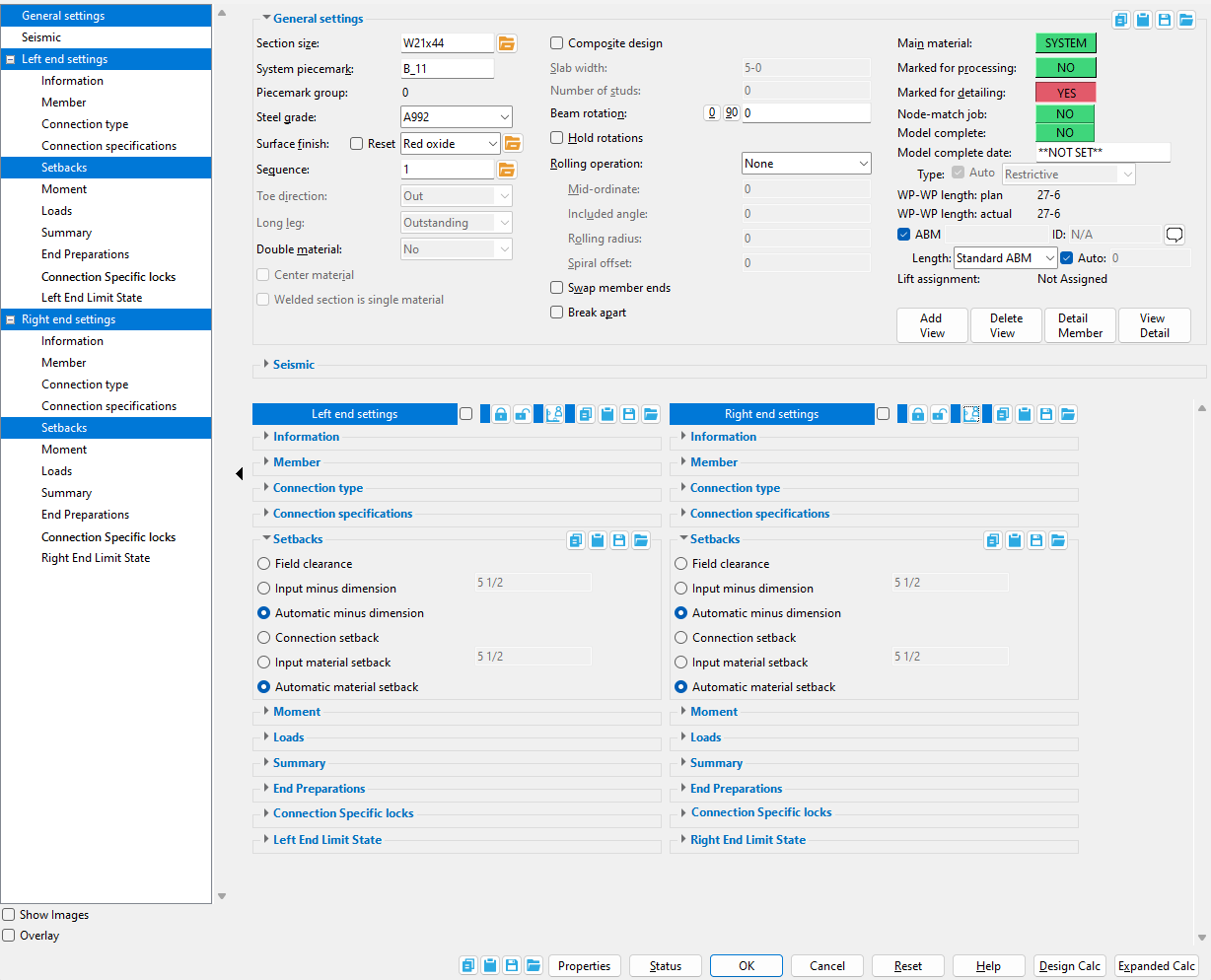
 Copy, Paste, Save, Load buttons:
- The position of these "form" buttons on the window tells you what settings they apply to. Click here for more information.
- You can
 Copy the settings on this window, then
  Paste those settings to a different edit window of the same type.
- You can
 Save the settings on this window to a file stored in a global folder that is used by your current version of SDS2. Give the file a name that will help other users identify its purpose. You can
  Load a saved file to replace the settings on this window (except Piecemark) with the settings that are stored in the file you select.
- When editing multiple windows at the same time, Paste and Load replace mixed entries to a single field with a single entry. Copy and Save ignore fields with mixed entries, treating them as if they have no entry or do not exist.
Properties opens the Edit Properties window, on which you can make entries to custom properties. If your current Job was set to use a legacy flavor when it was created, the window that opens is named Custom Properties , not Edit Properties.
Tip: The Edit Properties window can also be used to read  Log entries or review or type Notes.
Tip: The Member Properties command is an alternative to this button. It opens the Edit Properties window directly, without your first having to open a member edit window.
Status opens the Member Status Review window, which can give you additional information about the member, and which you can use to enter status information or designate a member as an existing member.
Note: This button shows  if one or more Repeat check boxes on the Member Status Review window do not match the checked-unchecked state of same-named fields in User and Site Options > Site > Member status items to copy/repeat. On the Status Review window, the fields that do not match User and Site Options are plotted in red .
OK (or the Enter key) closes the edit window and saves any changes you have made on the window to the member file.
Solids on OK: If the appropriate choice is made to User and Site Options > Modeling > Automatically process after modeling operation, then this member will automatically be regenerated (Create Solids will take place) after your press OK. Otherwise, you will have to manually Process and Create Solids in order for changes you made on this window to be fully updated in the 3D model.
Change all: If you Edit Member (one member only) and make a change that potentially triggers the Do you want to change all ... dialog and the 3D model contains more than one member of the same type that has the same piecemark as the member you changed, a yes-no dialog opens. On it is the question, Do you want to change all (members with this piecemark). Press the Yes button to change all the members; press the No button to change only this member.
Cancel (or the Esc key or the  button) closes the edit window without saving any changes that you have made. Cancel does not undo a Detail Member operation.
Note: If you opened this window while adding a member, Cancel brings you back to the work point location step of adding a member.
Tip: Any time you use Edit Member just to review a member (and you do not want to set the defaults for to-be-added members), the best way to close this window is to Cancel.
Reset undoes any changes made since you opened this window.
Exception: Reset does not undo changes made using the Add View, Delete View, Detail Member, and View detail buttons.

 ).
).