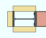
 Add Column Deck Support - Beam ( Modeling ) (a custom component )
Tool summary :
- Adds decking support material to a column. The material is positioned with reference to the top or bottom flange of a supported beam.
| YouTube video: Column Deck Support .
|
 |
Also see :
- Modeling (where custom components can be added)
- Custom components (topic)
- Component Plugin Setup ( Home > Project Settings > Job )
- Copy Component (to copy the deck supports to another beam)
- Move Component (to move the deck supports to another beam)
- Explode Component (to reduce the component to its constituent materials and welds)
- Component Selection Tool (to search for custom components of a selected type)
- Model Tree (to find custom components and select them for deletion, editing, etc.)
page 1 | contents | model > component > add > | toolbox
 To add, edit or delete the Column Deck Support - Beam custom component :
page 1 | contents | model > component > add > | toolbox
 Column Deck Support - Beam custom component settings :
------  Graphical ------
VIDEO 
With respect to " Graphical ," all custom components work much the same. This video demonstrates how it works on a Beam Stiffeners - Beam component.
A Column Deck Support - Beam component is automatically set to "
Graphical " whenever you make graphical changes to any of the supports -- for example, when you Edit Material or apply the Cut on Plane tool. This stops the component from being changed during Process and Create Solids . Click here for more information.
Instead of allowing the component to be made "
Graphical ," you may wish to Explode Component .
page 1 | contents | model > component > add > | toolbox
------  General settings ------
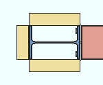
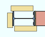
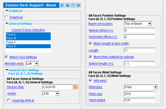
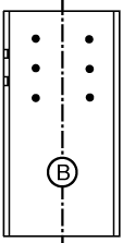
Column Faces Selection: Face A and/or Face B and/or Face C and/or Face D .You must select at least one face to get deck supports.
|
face A |
|
|
' Face B ' is web near side of the column.
' Face A ' is the left flange when you are looking at face B.
' Face C ' is the right flange when you are looking at face B.
' Face D ' is web far side of the column; that is, the reverse of face B.
If this box is checked (
), the same " Section size ," " Grade ," position settings, and weld settings are applied to the column deck supports on every column face selected .
If the box is not checked (
), options are provided on the Column Deck Support Beam Edit window to set each column face's deck supports independently of those on other column faces.
Member ends: Left or Right or Both . Each setting is available when there is a beam-to-column connection on that end.
' Left ' places column deck supports on the left end of the beam that you selected.
' Right ' places supports at the right end of the beam.
' Both ' creates a single custom component that places supports on both ends of the beam. Selecting that component selects all of its supports and welds on either end of the beam.
page 1 | contents | model > component > add > | toolbox
------  General Face Settings ------
------  Face [A, B, C, or D] Settings ------
Face General Settings
Section size: The column deck support's main material (e.g., ' L2x2x1/8 '). Only materials listed in the local shape file can be specified here.
To enter a section size: You can type in the section size that you want, or you can press the "file cabinet" browse button (
) and double-click any section that is on the list of available materials in the local shape file . Validation only lets you enter a material that is listed in the local shape file and that is either a wide flange, angle, channel, HSS/TS or W Tee.
Material grade: A36 or A572 or etc . The " Steel grade " of the W, L, C, HSS/TS or WT material that the support is made of.
Setup: If the grade of steel you want is not shown on the list box (
), you can use Home > Project Settings > Job > Material Grades and add it to the Wide Flange , Angle , Channel , HSS/TS , or WT Grades list.
Long leg vertical: ![]() or
or ![]() . This applies if the " Section Size " if the support is an angle whose legs are of unequal length. Otherwise, this field will be disabled ( grayed out ).
. This applies if the " Section Size " if the support is an angle whose legs are of unequal length. Otherwise, this field will be disabled ( grayed out ).
|
|
If this box is checked (
), the long leg of the angle is aligned vertically, parallel to the column.
If the box is not checked (
), the long leg of the angle extends horizontally.
Face Position Settings
Beam ref[erence] location: Top of Beam or Bottom of Beam .
|
" Vertical offset " = ' 0 ' |
|||||
|
|
||||
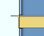
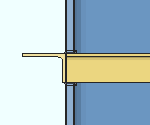
' Top of Beam ' positions the support with reference to the top flange of the beam.
' Bottom of Beam ' positions the support with reference to the bottom flange of the beam.
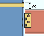
Vertical Offset (+/-): The distance (in the primary dimension " Units " or other units ) by which the support is offset above (+) or below (+) the " Beam ref location ."
|
In this example, " Vertical offset " is set to a positive value, and
|
Horizontal Offset (+/-): The distance (in the primary dimension " Units " or other units ) by which the support is offset horizontally. A positive (+) distance offsets the support to the right, relative to the face.
|
|
Match length to face width: ![]() or
or ![]() .
.
|
" |
|||||
|
|
||||
If this box is checked (
), the length of the support is -- depending on the column face it is placed at -- the flange width or the depth of the column. If "
Move Web material to outside " is not checked, and assuming that the " Horizontal Offset " is ' 0 ', the width on a web face is the column depth minus the k distances on either end of the support.
If the box is not checked (
), the length of the support is the " Length " that you enter. If the face is a web face, and if "
Move Web material to outside " is checked, its length will match the face width regardless of the " Length " that you enter or the setting to " Match length to face width ."
Length: The length (in the primary dimension " Units " or other units ) of the column deck support. This applies if " ![]() Match length to face width " is not checked; otherwise, this field will be disabled ( grayed out ). If the face is a web face, and if "
Match length to face width " is not checked; otherwise, this field will be disabled ( grayed out ). If the face is a web face, and if " ![]() Move Web material to outside " is checked, the setting made here is ignored for that face. Instead, the length will match the face width.
Move Web material to outside " is checked, the setting made here is ignored for that face. Instead, the length will match the face width.
Move Web material to outside: ![]() or
or ![]() . This applies when the column has flanges; that is, the column material is a WF, S, etc. If the column at an end is a Pipe or a HSS / TS, setting this option does nothing to that column's support material.
. This applies when the column has flanges; that is, the column material is a WF, S, etc. If the column at an end is a Pipe or a HSS / TS, setting this option does nothing to that column's support material.
|
|
If this box is checked (
), when the face is a column web, the deck support is moved to the edge of the column flanges. It also sets its length to match the face width.
If the box is not checked (
), the support is placed at the web of the column.
Extend length (+/-): The distance (in the primary dimension " Units " or other units ) by which the length that the material of a web face support is extended. This applies when " ![]() Move Web material to outside " is checked and when "
Move Web material to outside " is checked and when " ![]() Match length to face width " is unchecked.
Match length to face width " is unchecked.

|
el = " Extended length "
|
Face Weld Settings
' Yes ' instructs Add Column Deck Support - Beam to shop weld the deck supports to the column.
' No ' instructs Add Column Deck Support - Beam to not add welds.
Weld type: Fillet or Square groove or Bevel groove or V groove or Flare bevel groove . This sets the " Weld type " on the Weld Edit window in Modeling as well as the " Weld type " for the weld symbol on the column detail.
| symbol | name | weld used for... |
|
|
fillet | General welding of material. |
|
|
square groove | Butt joints. |
|
|
bevel groove | General full penetration welding of material. |
|
|
V groove | Butt joints of thicker material. |
|
|
flare bevel groove | For a radiused surface to flat surface. |
Weld size: A distance (in the primary dimension " Units " or other units ) that indicates depth of preparation, size or strength of the weld. This sets the " Weld size " on the Weld Edit window in Modeling as well as the " Weld size " for the weld symbol on the column detail.
Tail text: blank or a text string . This sets the " Supplementary tail text " on the Weld Edit window in Modeling as well as the " Supplementary tail text " for the weld symbol on the column detail.
|
This weld symbol's tail text is TYP . |
If this field is left ' blank ', a tail is not drawn on the weld symbol.
If a ' text string ' is entered, a tail with that text string as the tail text is drawn on the weld symbol.
page 1 | contents | model > component > add > | toolbox
