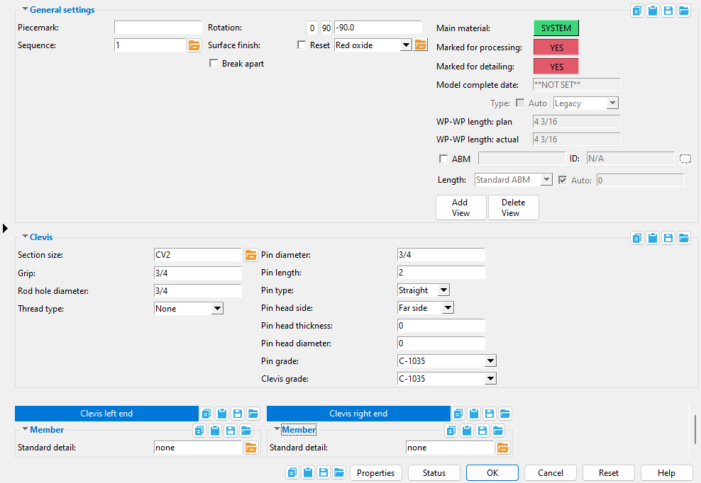
Clevis Edit window
( Modeling > F2 > "  Misc steel " > " Clevis ")
Selecting " Clevis " as the " Miscellaneous steel " type adds a custom member with clevis material to a 3D model.
The Clevis custom member is a superior alternative to " Miscellaneous -- Clevis ."
The edit window of this member features material and member options on the same window.
Its " General settings " include " Break apart " and " Rotation " which are not available for the legacy miscellaneous member.
- Warning! Don't make changes to the Clevis Material window that you can make on this window, Clevis Edit . Most changes made to this miscellaneous member's main material outside of this window will make the member graphical (" Main Material " = ' USER ').
- To open this window:
- Special indicators:


The " OK " button is disabled (grayed out) to indicate a validation error. Hover the " OK " button with your mouse pointer to get a listing of settings you need to change on this window. When all settings are valid, the " OK " button is enabled. 
Red-colored highlighting identifies an entry that is invalid. You need to change that setting, or you will not be able to close this window using " OK ." - " Properties " " Status " " OK " " Cancel " " Reset "
Also see :
- Clevis (topic)
- Miscellaneous member types (the complete list)
- Clevis Material (window can set Clevis Edit 's " Main Material " to ' USER ')
- Custom members (a clevis miscellaneous member is a custom member)
- Miscellaneous members versus legacy miscellaneous members (topic)
- Surfaces Connection (a custom component you can add to a miscellaneous member)
1 . A clevis miscellaneous member can be properly located and rotated even in an isometric view. Before adding the member, be aware of the following:
2 . To add a clevis miscellaneous member (in Modeling ):
Alternative 1 : Press F2 > check the box for "
Alternative 2 : Choose Model > Member > Prompt for Member Type > check the box for "
3 . Locate - Repeat - Return mouse bindings become active, and you are prompted to locate the clevis's work points. Two work points are required to lay out a clevis.
|
|
|
bindings |
3a : Select the appropriate Locate option.
3b : Left-click ( Locate ) at two different on-screen positions to define the member line between those two points. The first work point you enter when you add the clevis defines the left end of the member. The first point represented as an exact point after step 4, when the member is actually generated in the model. The second point determines the orientation of the member line with respect to the global coordinate system.

The first point that you locate is identified by an origin symbol . The origin symbol also tells you which end is the member's left end. The following illustration shows the difference between laying out work points from left to right versus right to left.
If you Model > Member > Isolate > ... a clevis miscellaneous member, you will find that the member's MAIN VIEW shows the member's origin symbol (
) to be to your left. This is true for any miscellaneous member -- even if the origin symbol for the member is to your right in a plan view. The MAIN VIEW in member isolation directly correlates to the main view of the miscellaneous member's detail.
4 . The Clevis Edit window opens. On it are settings for the clevis that you are adding.
4a : Enter the " Section size " for the clevis miscellaneous member.
4b : Enter a " Rod hole diameter " for the clevis.
4c : Enter a " Pin diameter , " and " Maximum pin [hole] diameter ."
4d : Press the " OK " button at the bottom of the window to apply your settings and close this window.
Tip 1: Point 1 of the clevis defines the center of the " Pin hole diameter " as well as the clevis's left end.
Tip 2: Point 1 and point 2 together define the axis around which the " Rod hole diameter " is centered. The length of the clevis is set per the selected " Section size " based on that section's local shape file specifications.
Tip 3: Be sure that you define your selections on this window per the " Section size " that you select. For example, if you set a " Pin diameter " that is greater than the " Maximum pin [hole] diameter " in the local shape file, you'll get a material clash.
Note: The default settings on this window are those of the last clevis miscellaneous member added or edited in this session of Modeling . Even if all you do is double-click a clevis member and press " OK " on its edit window, its settings become the defaults for the next-added clevis miscellaneous member. You therefore only need to make changes to those settings which are different for this member.
5 . If User and Site Options > Modeling > " Process after modeling operation " is ' Process and create solids ', the new clevis will have automatically undergone all phases of Process and Create Solids and will show up in a solid form . If that option is ' Process ' or ' Do nothing ', then the member line of the clevis you just added shows up on screen in stick form , and you will have to Process > Process and Create Solids in order to have the member piecemarked and able to be displayed in a solid form. Do one (1) of the following:
|
|
|
bindings |
Alternative 1 : Move the mouse pointer (
) and middle-click ( Repeat ) to lay out a clevis just like the last one beginning at the point where the point location target (
) is at. The X, Y global axes location of the repeated clevis will begin from the located repeat point (where the target is at). The clevis's Z location and other settings will be that of the last-added or last-edited clevis.
Alternative 2 : Follow these instructions beginning with step 3 to add a clevis with different settings than the one you just laid out.
Alternative 3 : Right-click ( Return ) if you are done adding clevis.
------ Clevis ------
Section size: Any clevis material section size that is listed in the local shape file . You must enter a section size in order to add the clevis.
To enter a section size: You can type in the section size that you want, or you can press the "file cabinet" browse button (
) and double-click a section size from the list of available clevis material. If the section you enter does not exist in the local shape file, validation prompts you to make a different entry.
Detailing after changing the " Section size " affects the " Description " and " Unit Weight " fields on the member bill of material.
The following can read the choice made here when " Main material " is ' SYSTEM ':
Connection Design Locks: Brace Connection To Gusset
Report Writer: MemberMaterial.Material.SubMaterial.MaterialFile.SectionSize
Grip: The distance (in the primary dimension " Units " or other units ) between the prongs of the clevis.
The following can read the choice made here when " Main material " is ' SYSTEM ':
Connection Design Locks: Brace Connection To Gusset
Report Writer: XXXXX . Grip
Advanced Selection: Grip
Parametric module: Grip
Rod diameter: The diameter (in the primary dimension " Units " or other units ) of the hole for inserting the rod.
The following can track the choice made here when " Main material " is ' SYSTEM ':
Report Writer: XXXXX . RodDiameter
Advanced Selection: RodDiameter
Parametric module: RodDiameter
Thread type: None or Left handed or Right handed . If the end of the round bar that is to be fitted to this clevis uses ' Left handed ' as its " Thread type ," you will probably want to select ' Left handed ' here.
The following can read the choice made here when " Main material " is ' SYSTEM ':
Connection Design Locks: Brace Connection To Gusset
Round Bar Material: Thread type
Turnbuckle Material: Left thread type and Right thread type
Report Writer: XXXXX . LeftThreadType
Pin diameter: The diameter of the shaft of the clevis pin (in the primary dimension " Units " or other units ).
The following can read the choice made here when " Main material " is ' SYSTEM ':
Connection Design Locks: Brace Connection To Gusset
Report Writer: XXXXX . PinDiameter
Advanced Selection: PinDiameter
Parametric module: PinDiameter
Pin length: The distance (in the primary dimension " Units " or other units ) from one end of the clevis pin to its opposite end. The length of the pin includes its head.
Connection Design Locks: Brace Connection To Gusset
Pin type: Straight or Headed or None .
|
Also see " Pin type " |
' Straight ' specifies a clevis pin that is a consistent diameter along the entirety of its " Pin length ."
' Headed ' specifies a clevis pin with a head placed on the selected " Pin head side ." The size of the head is controlled by the entries made to " Pin head thickness " and " Pin head diameter ."
Pin head side: Near side or Far side .
|
Tip: Isolate Material shows a view of a clevis in which its left end is to your left and its near side is toward you. |
' Near side ' puts the head on the near-side end of the clevis pin.
' Far side ' puts the head on the far-side end of the clevis pin.
Pin head thickness: The distance (in the primary dimension " Units " or other units ) along the length of the pin that you want the " Pin head diameter " to apply when ' Headed ' is selected as the " Pin type ."
Connection Design Locks: Brace Connection To Gusset
Pin head diameter: The diameter of the pin head (in the primary dimension " Units " or other units ) when ' Headed ' is selected as the " Pin type ."
Connection Design Locks: Brace Connection To Gusset
Pin grade: C-1035 or F22 Class3 or etc. This is the grade of steel for the clevis pin.
Setup: If the grade of steel you want is not shown as a list box (
) for this field, you can use Home > Project Settings > Job > Turnbuckle / Clevis / Pin Grades to add it to this list.
The following can read the choice made here when " Main material " is ' SYSTEM ':
Connection Design Locks: Brace Connection To Gusset
Advanced Selection: MaterialGrade
Parametric module: MaterialGrade
Clevis grade: C-1035 or F22 Class3 or etc. This is the grade of steel for the clevis.
Setup: If the grade of steel you want is not shown as a list box (
The following can be used to track the choice made here when " Main material " is ' SYSTEM ':
Bill of material: Steel Grade
Advanced Selection: MaterialGrade
Parametric module: MaterialGrade
|
|
------ Member ------
Standard detail: None or a standard detail name . To apply a standard detail, you can type in the file name of the drawing (if you know it), or press the "file cabinet" browse button ( ![]() ) and double-click any job standard detail or global standard detail that is on the list.
) and double-click any job standard detail or global standard detail that is on the list.
If ' none ' is entered here, then no standard detail will be applied on this end of the miscellaneous member when it is automatically detailed .
If a ' standard detail name ' is entered here, the next time you auto detail this miscellaneous member, the reference point of the standard detail will align with the input work point on this end of the member, and the standard detail's bill of material will be combined with the member's bill of material. The detail is placed on a layer that is named after the standard detail plus a "_L" or "_R" suffix.

