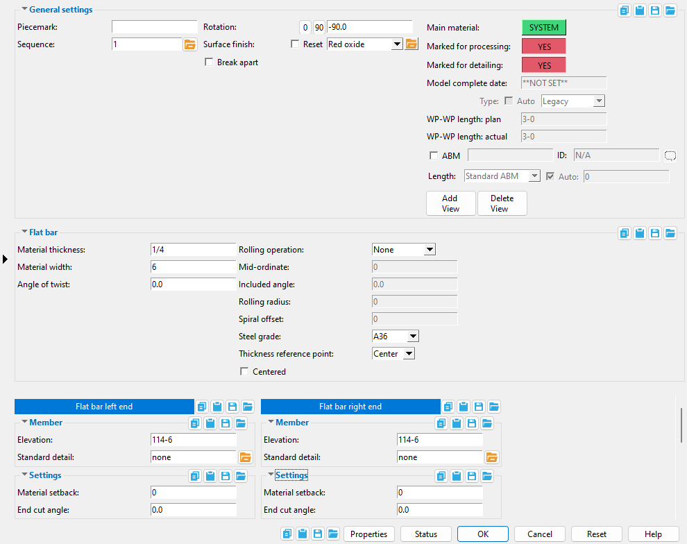
Flat Bar Edit window
( Modeling > F2 > "  Misc steel " > " Flat Bar ")
Selecting " Flat Bar " as the " Miscellaneous steel " type adds a custom member with flat bar material to a 3D model.
The Flat Bar custom member is a superior alternative to " Miscellaneous -- Flat Bar ."
The edit window of this member features material and member options on the same window.
Its " General settings " include " Break apart " and " Rotation ," which are not available for the legacy miscellaneous member.


The " OK " button is disabled (grayed out) to indicate a validation error. Hover the " OK " button with your mouse pointer to get a listing of settings you need to change on this window. When all settings are valid, the " OK " button is enabled. 
Red-colored highlighting identifies an entry that is invalid. You need to change that setting, or you will not be able to close this window using " OK ."
Also see :
- Flat Bar (topic)
- Miscellaneous member types (the complete list)
- Custom members (a flat bar miscellaneous member is a custom member)
- Flat Bar Material (window can set Flat Bar Edit 's " Main Material " to ' USER ')
- Miscellaneous members versus legacy miscellaneous members (topic)
- Surfaces Connection (a custom component you can add to a miscellaneous member)
1 . A flat bar miscellaneous member can be properly located and rotated even in an isometric view. Before adding the member, be aware of the following:
- The key to ensuring that a miscellaneous member's material is properly oriented in the model is proper location of the member's work points and proper " Rotation " around the member line established by those work points. A flat bar's material can also be " Centered " with respect to its member line.
- Before adding a flat bar miscellaneous member in Modeling , you should Open ( Ctrl + o ) a view that will facilitate the locating of the work points.
- Work points for sloping flat bar should be added in a view that is at the desired slope. To create such a view, you can use Navigate > Snap to Surface or View > Section View .
- To lay out a perfectly horizontal flat bar, open a plan view at the desired elevation.
- Work points for a perfectly vertical flat bar can be located in an elevation view .
- You can adjust the " Elevation " of a flat bar miscellaneous member's work points on its edit window. If you want the elevation of both work points to be at a particular elevation, you may want to open a plan view at the desired elevation.
- You may want to add construction lines so that there are INCL points for locating work points.
- Tools and widgets related to the locating of points include the point-location target (
 ), the X-Y-Z display , Modeling > Locate options and Offset Controls .
- Tools related to the adding of Modeling views include Navigate > Snap to Surface and View > Section View and File > View/Grids > Add Grid Line and others.
2 . To add a flat bar miscellaneous member (in Modeling ):
Alternative 1 : Press F2 > check the box for "
Alternative 2 : Choose Model > Member > Prompt for Member Type > check the box for "
3 . Locate - Repeat - Return mouse bindings become active, and you are prompted to locate the flat bar's work points. Two work points are required to lay out flat bar.
|
|
|
bindings |
3a : Select the appropriate Locate option.
3b : Left-click ( Locate ) at two different on-screen positions to define the member line between those two points. The first work point you enter when you add the flat bar defines the left end of the member. Both points are represented as exact points after step 4, when the member is actually generated in the model.

The first point that you locate is identified by an origin symbol . The origin symbol also tells you which end is the member's left end. Depending on the choice made for the bar's " Thickness reference point ," its member line will lie on the ' NS ', ' FS ', or ' Center ' of the bar's thickness, and, provided that " Centered " is not checked (
), its member line will lie on an edge of the plate. The following illustration shows the difference between locating the two points from left to right versus right to left.
You can set material back from the left end -- that is, from the first work point entered -- when you enter positive left end " Material setback ." Similarly, you can enter a right end setback.
If you Model > Member > Isolate > ... a flat bar miscellaneous member, you will find that the member's MAIN VIEW shows the member's origin symbol (
) to be to your left. This is true for any miscellaneous member -- even if the origin symbol for the member is to your right in a plan view. The MAIN VIEW in member isolation directly correlates to the main view of the miscellaneous member's detail.
Best practice when adding a miscellaneous member in a plan view is to input the member from left to right or from bottom to top. That way, when you add a grid line from left to right, the near side of the member, as determined by the location of its left end , will be the side looking toward the bottom or toward the right of the screen.
4 . After you are done laying out work points, the Flat Bar Edit window opens. On it are settings of the flat bar you are adding.
4a : Enter a " Material thickness " or use the default.
4b : Choose whether you want the flat bar to be " Centered " or not.
4c ( optional ): The " Left/right end settings " of this window let you specify cuts or material setbacks on the ends of the flat bar. The left end is the end associated with the first point you located in step 3.
4d : Press the " OK " button to apply your settings and close this window.
Note: The default settings on this window are those of the last flat bar miscellaneous member added or edited in this session of Modeling . Even if all you do is double-click a flat bar member and press " OK " on its edit window, its settings become the defaults for the next-added flat bar miscellaneous member. You therefore only need to make changes to those settings which are different for this member.
5 . If User and Site Options > Modeling > " Process after modeling operation " is ' Process and create solids ', the new plate will have automatically undergone all phases of Process and Create Solids and will show up in a solid form . If that option is ' Process ' or ' Do nothing ', then the member line of the flat bar you just added shows up on screen in stick form , and you will have to Process > Process and Create Solids in order to have the member piecemarked and able to be displayed in a solid form. Do one (1) of the following:
|
|
|
bindings |
Alternative 1 : Move the mouse pointer (
) and middle-click ( Repeat ) to lay out a flat bar just like the last one beginning at the point where the point location target (
Alternative 2 : Follow these instructions beginning with step 3 to add a flat bar with different settings than the one you just laid out.
Alternative 3 : Right-click ( Return ) if you are done adding flat bar.
------ Flat bar ------
| Defaults: If you press " OK " to close this window, the entries made to " Material thickness ," " Material width ," " Angle of twist ," " Rolling operation," and " Centered ," become the defaults for the next-added flat bar. |
Material thickness: The thickness (in the primary dimension " Units " or other units or the gage ) of the bar stock being added/edited. This dimension is measured along the flat bar's Z member axis .
To enter gage material: Type in the ' gage number' followed by ' ga ' (example: ' 4ga ' is rewritten as ' 4GA ' when you Tab out of the field). Right-click tells you the stored thickness (based on industry standards), from which the weight of the gage material is calculated. Allowable gages are any whole number from 3 to 38 . You can also enter an exact decimal thickness to get the gage (example: ' .1345 ' becomes ' 10GA ' when you Tab out of the field). The " Description " for a gage flat bar follows the format: ' flat bar prefix ' + ' numberGA ' + ' x ' + ' width ' (example: FL16GAx15 1/2 ).
Thickness precision: You can enter a plate " Material thickness " that is more precise than the " Dimension precision " that is set at Home > Project Settings > Fabricator > Detailing > Drawing Presentaton . For example, if you enter ' 5/32 ' and the " Dimension precision " is ' 1/16 ', the thickness of the plate will be ' 5/32 '. The thickness you enter will be reflected in the " Description " and will propagate to the bill of material, reports, etc. The setup option to " Round flat plate values " does not affect this. Be aware that the Ruler measures to whatever the " Dimension precision " is set to, which means that the plate's measured thickness may not exactly match its actual thickness.
The following can be used to track the choice made here when " Main material " is ' SYSTEM ':
Report Writer: XXXXX . Thickness
Advanced Selection: Thickness
Parametric module: Thickness
Material width: The width (in the primary dimension " Units " or other units ) of the bar stock being added/edited. This dimension is measured along the flat bar's Y member axis . It is permissible to enter a material width dimension that is longer than the flat bar's length.
Setup: Force flat bar description to use smaller of length & width
The following can track the choice made here when " Main material " is ' SYSTEM ':
Report Writer: XXXXX . Width
Advanced Selection: Width
Parametric module: Width
Angle of twist: 0 (zero) degrees or the positive or negative (-) number of degrees of twist about the member line of the flat bar.
' 0 ' (zero) results in straight (not twisted) member.
Entering a ' number of degrees ' causes the left end of the member's main material to remain fixed, while the right end is rotated the number of degrees entered. Validation can generate twists to .06 degree. Assuming you are looking from the right end toward the left end of the material, a positive entry rotates the main material counterclockwise.
The following can reveal the choice made here when " Main material " is ' SYSTEM ':
Report Writer: XXXXX . MaterialTwistAngle
Advanced Selection: MaterialTwistAngle
Parametric module: MaterialTwistAngle
Rolling operation: None or Camber or Weak axis or Strong axis . The center of curvature for each of these choices (except ' None ') is midway between the left and right ends of the flat bar.
None

|
Camber
|
Weak axis
|
Strong axis
|
' None ' makes the flat bar straight (not curved).
' Camber ' produces parabolic bending along the strong axis of the flat bar with the ends fixed. The " Mid-ordinate " sets the offset at mid-span and the direction (+ or -) of that offset.
' Weak axis ' or ' Strong axis ' rolling produces bending that is circular. The two ends of the flat bar are not fixed; that is, if the ends were vertical before the operation, they may not be vertical afterwards. The value entered to " Mid-ordinate " or " Included Angle " or " Rolling radius " sets the amount of curvature. A " Spiral offset " may also be set.
The following can be used to show the choice made here when " Main material " is ' SYSTEM ':
Report Writer: XXXXX . RollTypeDescription
Mid-ordinate: The positive or negative (-) distance (in the primary dimension " Units " or other units ) that the flat bar is offset at mid-span as a result of a " Rolling operation " of ' Camber ' or ' Strong Axis ' or ' Weak Axis '. The sign (+ or -) sets the direction of offset.
Camber with a positive mid-ordinate ( +m )
 |
Camber with a negative mid-ordinate ( -m )
 |
| Weak axis rolling with a positive mid-ordinate
( rolling toward the near side ) |
Weak axis rolling with a negative mid-ordinate
( rolling toward the far side )  |
Strong axis rolling with a positive mid-ordinate ( +m )
 |
Strong axis rolling with a negative mid-ordinate ( -m )
 |
The following can show the choice made here when " Main material " is ' SYSTEM ':
Report Writer: XXXXX . MidOrdinate
Advanced Selection: MidOrdinate
Parametric module: MidOrdinate
Included angle: The positive or negative (-) number of degrees that defines the angle of curvature for a " Rolling operation " that is set to ' Strong Axis ' or ' Weak Axis '. This option applies if if the entry to the " Mid-ordinate " field is ' 0 '.
|
i = included angle. Extrapolate a circle from the inside curvature of the member, then draw a line along each end of the member. The lines will meet at the center of the imaginary circle, and their included angle is the angle entered here. |
If the left end (work point 1) of the flat bar is to your left: A ' positive number ' of degrees raises the center of the flat bar's curvature on your computer screen. A ' negative (-) number ' makes the center of the member's curvature lower on your computer screen than its two ends.
The following can be used to track the choice made here when " Main material " is ' SYSTEM ':
Report Writer: XXXXX . IncludedAngle
Advanced Selection: IncludedAngle
Parametric module: IncludedAngle
Rolling radius: A positive or negative (-) distance (in the primary dimension " Units " or other units -- up to +/- 120,000 inches) that defines the amount of curvature of the flat bar when the " Rolling operation " is ' Strong axis ' or ' Weak axis '. The smaller the " Rolling radius " (+ or -), the greater the curvature. This option applies if if the entries to both the " Mid-ordinate " and " Included angle " fields are ' 0 '.
|
r = rolling radius. If you were to extrapolate a circle from the inside curvature of the member, the distance from any point on the inside curve of the top/bottom flange to the center of the circle is the distance entered here. |
If the left end (work point 1) of the flat bar is to your left: A ' positive rolling radius ' raises the center of the member's curvature on your computer screen. a ' negative (-) rolling radius ' makes the center of the member's curvature lower on your computer screen than its two ends.
The following can track the choice made here when " Main material " is ' SYSTEM ':
Report Writer: XXXXX . RollingRadius
Advanced Selection: RollingRadius
Parametric module: RollingRadius
Spiral offset: The positive or negative (-) distance (in the primary dimension " Units " or other units ) that you want the right end of the flat bar to be offset from the left end. The left end of the flat bar remains fixed. This applies when the " Rolling operation " is ' Weak axis ' or ' Strong axis ', and a non-zero entry has been made to the " Mid-ordinate ," " Included angle ," or the " Rolling Radius " fields.
For a flat bar whose member line is in the plane of a plan view: A ' positive distance ' raises the elevation of the right end. A ' negative (-) distance ' lowers the elevation of the right end.
The following can be reveal the choice made here when " Main material " is ' SYSTEM '.
Report Writer: XXXXX . SpiralOffset
Advanced Selection: SpiralOffset
Parametric module: SpiralOffset
Thickness reference point: Center or FS or NS . ' FS ' stands for far side, ' NS ' for near side. This option orients the " Material thickness " of the flat bar with respect to its member line.
|
|||
| A section view of the same flat bar , but with different depth reference points. The view looks perpendicular to the plan view (at 100 ft) in which the flat bar was added. |
' Center ' aligns the thickness of this flat bar so that it is centered with respect to the bar's work points.
' FS ' aligns the flat bar so that its far side surface includes the bar's member line. When the bar was added in a plan view at the default " Rotation " (' -90 '), the far side is the face that is away from you when you are in that view and when the bar was not subsequently rotated. You might select this setting, for example, when your work plane is the Surface of a material, you have located two points on that surface to add this flat bar, and you want this bar's far side to be flush to that surface.
' NS ' if you added the flat bar in a plan view and want its near side to be at the elevation of the bar's work points. The near side is the face of the flat bar that faces you when you are in the view in which the bar was added, assuming the bar was added in a plan view at the default " Rotation " (' -90 ' in a plan view) and was not subsequently rotated.
Steel grade: A36 or A572 or etc. This is the grade of steel for the flat bar whose settings are defined on this window.
Setup: If the steel grade you want is not on the list box (
) for this field, you can Home > Project Settings > Job > Flat Bar Grades to add it to the list.
Tip: Changing " Steel grade " does not cause the flat bar to be regenerated. This means that, if you change this setting only, material operations such as a Cut Layout may, optionally, be preserved.
The following can show the choice made here when " Main material " is ' SYSTEM '.
Report Writer: MemberMaterial.Material.SubMaterial.MaterialGradeDescription
Advanced Selection: MaterialGrade
Parametric module: MaterialGrade
Centered: ![]() or
or ![]() . This option orients the " Material width " of the flat bar with respect to its member line.
. This option orients the " Material width " of the flat bar with respect to its member line.
 |
 |
If this box is checked (
If the box is not checked (
|
|
|
------ Member ------
End elevation: The elevation (in the primary dimension " Units " or other units ) of the work point at this end of the flat bar. For a non-sloping bar, both the left and right end elevations are the same. When you add the flat bar, its work points are placed in your current view's reference elevation until you change their elevations here, on this window.
| A flat bar has two exact points , whose elevation you can change by changing the member's left- and/or right-end " End elevation ." |
|
To determine the end elevation on flat bar in the 3D model, use Construction Line Add or a similar tool, select EXPT as the Locate option, then snap the point location target to the work point at the end of the member. The Z coordinate reported in the X-Y-Z display tells you the elevation at the snapped-to exact point.
Tip: You should use this option instead of rotating a flat bar member's material to change its left- or right-end elevation. For complex situations, you can Model > Member > Move/Stretch one or the other of its work points.
Standard detail: None or a standard detail name . To apply a standard detail, you can type in the file name of the drawing (if you know it), or press the "file cabinet" browse button ( ![]() ) and double-click any job standard detail or global standard detail that is on the list.
) and double-click any job standard detail or global standard detail that is on the list.
If ' none ' is entered here, then no standard detail will be applied on this end of the miscellaneous member when it is automatically detailed .
If a ' standard detail name ' is entered here, the next time you auto detail this miscellaneous member, the reference point of the standard detail will align with the input work point on this end of the member, and the standard detail's bill of material will be combined with the member's bill of material. The detail is placed on a layer that is named after the standard detail plus a "_L" or "_R" suffix.
------ Settings ------
Material setback: The positive or negative (-) distance (in the appropriate " Units ") that you want the left or right end of the flat bar to be displaced from its work point.
A ' positive material setback ' makes the flat bar member shorter. The distance is subtracted from the distance spanned by the bar's member line to give you the length of the bar.
A ' negative (-) material setback ' makes the flat bar longer. The distance is also subtracted from the distance spanned by the bar's member line to give you the length of the bar.
The following can be used to show the choice made here when " Main material " is ' SYSTEM ':
Report Writer: XXXXX . MaterialSetbackLeftEnd
Report Writer: XXXXX . MaterialSetbackRightEnd
Advanced Selection: MaterialSetback[0] or MaterialSetback[1]
Parametric module: MaterialSetback[0] or MaterialSetback[1]
End cut angle: Any angle from 89 to -89 degrees. The cut will be made along the width of the flat bar.
In this example, the left end of the flat bar is to your left on your computer screen and negative distances along its Y member axis are toward the bottom of the screen. The flat bar's width is shown as vertical in this view: ' 0 ' (zero) square cuts the end. A ' positive angle ' is measured counterclockwise from a perpendicular bisector to the member line. A ' negative (-) angle ' is measured clockwise from a perpendicular bisector to the member line.
The following can read the choice made here when " Main material " is ' SYSTEM '.
Report Writer: XXXXX . WebCutLeftEnd
Report Writer: XXXXX . WebCutRightEnd
Advanced Selection: WebCutEnd[0] or WebCutEnd[1]
Parametric module: WebCutEnd[0] or WebCutEnd[1]

