 Add Welded Studs ( Modeling ) (a custom component )
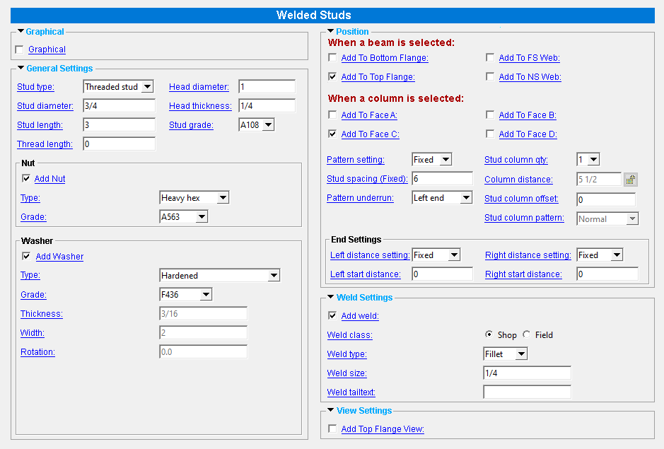
Tool summary :
 |
Also see :
| YouTube video: Welded Studs .
|
- Material Add Shear Stud or Threaded Stud (another way to add a stud)
- Number of studs (appends stud annotations to beams in erection views)
- Modeling (where custom components can be added)
- Custom components (topic)
- Component Plugin Setup ( Home > Project Settings > Job )
- Copy Component (to copy the deck supports to another beam)
- Move Component (to move the deck supports to another beam)
- Explode Component (to reduce the component to its constituent materials and welds)
- Component Selection Tool (to search for custom components of a selected type)
- Model Tree (to find custom components and select them for deletion, editing, etc.)
page 1 | contents | model > component > add > | toolbox
 To add, edit or delete the Welded Studs custom component :
page 1 | contents | model > component > add > | toolbox
------  Graphical ------
VIDEO 
With respect to " Graphical ," all custom components work much the same. This video demonstrates how it works on a Beam Stiffeners - Beam component.
A Welded Studs component is automatically set to "
Graphical " whenever you make graphical changes to any of the studs -- for example, when you Edit Material or perform a material cutting operation on Welded Studs material. This stops the component from being changed during Process and Create Solids . Click here for more information.
Instead of allowing the component to be made "
Graphical ," you may wish to Explode Component
page 1 | contents | model > component > add > | toolbox
------  General settings ------
Stud type: Shear stud or Threaded stud .
' Shear stud ' models non-threaded studs that may be field or shop welded. A " Head diameter " and " Head thickness " may be specified for the shear studs. The prefix set for " Shear Stud " in Home > Project Settings > Fabricator > Piecemarking > Member and Material Piecemarking > the " Prefixes " tab is added to the " Description " on the Modeling material's General Information window and in the Drawing Editor 's member bill of material. For example, a shear stud with a " Stud diameter " of '1/2' inch is automatically described as WS 1/2 when WS is the " Description " in Fabricator Setup .
' Threaded stud ' models threaded studs that may be field or shop welded. You can add threads to the studs by specifying a " Thread length ." The prefix set for " Threaded Stud " in Member and Material Piecemarking > the " Prefixes " tab is added to the " Description " on the material's General Information window and in the Drawing Editor 's member bill of material. For example, a threaded stud with a " Stud diameter " of '1/2' inch is automatically described as THD STUD 1/2 when THD STUD is the " Description " in Fabricator Setup .
Stud diameter: The rod diameter (in the primary dimension " Units " or other units ) of the shear studs or threaded studs.

|
d = diameter |
Also see: Changing the shear stud's diameter causes the " Weight of item " on the material's General Information window to be recalculated.
Stud length: The distance (in the primary dimension " Units " or other units ) between the two ends of each shear stud or threaded stud. A shear stud's head is included in its length.
| l = length |

|
Thread length: The distance (in the primary dimension " Units " or other units ) from the right end of the material to where you want the threaded area to end. The right end is the end opposite to the origin reference point symbol that is shown at the beginning of a Rotate Material operation. The following illustration shows how Modeling represents the threaded area when the round bar is displayed in solid opaque form. This does not affect auto detailing . This applies when the " Stud type " is ' Threaded stud ; otherwise, this field will be disabled ( grayed out ).
tl = thread length
 |
Head diameter: The diameter (in the primary dimension " Units " or other units ) of the heads of the shear stud The " Stud type " must be ' Shear stud ' to get a head on the studs.

|
hd = head diameter |
Tip: Making this the same as the " Stud diameter " results in shear studs without heads.
Head thickness: The distance (in the primary dimension " Units " or other units ) between the top of the heads of the shear studs and the lower lips of the heads of the shear studs. The " Stud type " must be ' Shear stud ' to get a head on the studs.
| ht = head thickness |

|
Tip: Enter a " Head thickness " of ' 0 ' if you want a shear stud without a head.
Stud grade: A108 or A493 or etc. This is the grade of steel for the shear stud or threaded stud whose settings are defined on this window.
Setup: If the grade of steel you want is not shown in the list box (
), you can use Home > Project Settings > Job > Material Grades > Shear and Threaded Stud Grades to add it to this list.
Nut (options are available when " Stud type " is ' Threaded stud ')
Add Nut: ![]() or
or ![]() . Generates nuts at the right ends of the studs. The right end is the end opposite to the origin reference point symbol that is shown at the beginning of a Rotate Material operation.
. Generates nuts at the right ends of the studs. The right end is the end opposite to the origin reference point symbol that is shown at the beginning of a Rotate Material operation.
Type: Heavy hex or Heavy square or Jam . This applies when " ![]() Add Nut " is checked; otherwise, this field will be disabled ( grayed out ).
Add Nut " is checked; otherwise, this field will be disabled ( grayed out ).
|
|
|
' Heavy square ' generates a square-shaped nut on the studs.
' Heavy hex ' generates a hexagon-shaped nut.
' Jam ' generates a jam nut.
Grade: Any grade entered to the " Nuts " tab at Home > Project Settings > Job > Bolts, Washers, and Holes > Nut and Washer Schedule for the selected type (' Heavy square ' or ' Heavy hex ' or ' Jam ') can be selected on the list box ( ![]() ) for this field. This applies when "
) for this field. This applies when " ![]() Add Nut " is checked; otherwise, this field will be disabled ( grayed out ).
Add Nut " is checked; otherwise, this field will be disabled ( grayed out ).
Washer (options are available when " Stud type " is ' Threaded stud ')
Add Washer: ![]() or
or ![]() . Generates washers that are set back from the right end of the studs to accomodate nuts. The right end is the end opposite to the origin reference point symbol that is shown at the beginning of a Rotate Material operation.
. Generates washers that are set back from the right end of the studs to accomodate nuts. The right end is the end opposite to the origin reference point symbol that is shown at the beginning of a Rotate Material operation.
Type: Hardened or Flat or Bevel or Hillside or Direct tension indicator or Double thick hardened or Heavy plate or Square plate or Round plate . This applies when " ![]() Add Washer " is checked; otherwise, this field will be disabled ( grayed out ).
Add Washer " is checked; otherwise, this field will be disabled ( grayed out ).
| Type | shape | BOM |
| hardened |
|
HD |
| flat |
|
FL |
| bevel |
|
BVL |
| hillside |
|
HLS |
| direct tension indicator |
|
DTI |
| double thick hardened |
|
DTHD |
| square
plate |
|
PL |
| round
plate |
|
RPL |
| heavy
plate |
|
HVPL |
Grade: Any grade that has been entered to the " Washers " tab at Home > Project Settings > Job > Bolts, Washers, and Holes > Nut and Washer Schedule for the selected type (' Hardened ' or ' Flat ' or ' Bevel ' or etc.) can be selected on the list box ( ![]() ) for this field. This applies when "
) for this field. This applies when " ![]() Add Washer " is checked; otherwise, this field will be disabled ( grayed out ).
Add Washer " is checked; otherwise, this field will be disabled ( grayed out ).
Thickness: The thickness (in the primary dimension " Units " or other units ) of the square plate or round plate or heavy plate or double thick hardened washers. By default, this the thickness set in Washer Settings for the " Type " chosen until you change it here, in this window. This applies when ![]() Add Washer " is checked; otherwise, this field will be disabled ( grayed out ). It is also disabled if the " Type " is not a plate washer or a double thick hardened washer.
Add Washer " is checked; otherwise, this field will be disabled ( grayed out ). It is also disabled if the " Type " is not a plate washer or a double thick hardened washer.
t = thickness

Width: The length or width of a square washer, or the diameter of a round plate washer. Your entry is interpreted as being in the primary dimensioning " Units ." This applies when " ![]() Add Washer " is checked; otherwise, this field will be disabled ( grayed out ). It is also disabled if the " Type " is not a plate washer or a flat washer.
Add Washer " is checked; otherwise, this field will be disabled ( grayed out ). It is also disabled if the " Type " is not a plate washer or a flat washer.
w = width

Rotation: A positive or negative (-) number of degrees (from 999999 to - 99999 ). A rotation can be applied when ' Square plate ' or ' Bevel ' or ' Hillside ' or ' Heavy plate ' is the selected " Type " of washer. This applies when " ![]() Add Washer " is checked; otherwise, this field will be disabled ( grayed out ).
Add Washer " is checked; otherwise, this field will be disabled ( grayed out ).
0 degrees
 |
10 degrees
 |
25 degrees
 |
45 degrees
 |
' 0 ' degrees makes the edges of the washer parallel with the edges of your computer screen (assuming that the head of the bolt is shown flat on your computer screen).
A positive number rotates the washer clockwise when you are looking at the head of the bolt. Point 1 is the head end of the bolt grip in an Add Bolt Point to Point operation.
A negative number rotates the washer counterclockwise when you are looking at the head of the stud.
page 1 | contents | model > component > add > | toolbox
------  Position ------
" Add to Flange " and " ...Web " options are available when the selected member is a beam. You must select at least one of these options to get studs.
If this box is checked (
), studs are added to the bottom flange of the selected beam parallel to its center line.
If the box is not checked (
), studs are not added to the bottom flange of the selected beam.
If this box is checked (
), studs are added to the top flange of the selected beam parallel to its center line.
If the box is not checked (
), studs are not added to the top flange of the selected beam.
If this box is checked (
), studs are added to the selected beam's far side web.
If the box is not checked (
), studs are not added to the selected beam's far side web.
If this box is checked (
), studs are added to the selected beam's near side web.
If the box is not checked (
), studs are not added to the selected beam's near side web.
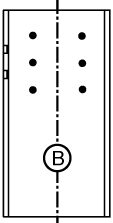
" Add To Face... " options are available when the selected member is a column. You must select at least one of these options to get studs.
|
face A |
|
|
Face B is web near side of the column.
Face A is the left flange when you are looking at face B, while Face C is the right flange. Face D is the reverse of face B.; that is, web far side of the column. |
If this box is checked (
), studs are added to face B of the column.
If the box is not checked (
), studs are not added to face B.
If this box is checked (
), studs are added to face C of the column.
If the box is not checked (
), studs are not added to face C.
If this box is checked (
), studs are added to face B of the column.
If the box is not checked (
), studs are not added to face B.
If this box is checked (
), studs are added to face D of the column.
If the box is not checked (
), studs are not added to face D.
Pattern setting: Fixed or Equal .
' Fixed ' spaces all of the welded studs using the " Stud spacing ." If the length of the beam or column cannot be equally divided by this spacing, the remaining length is used to space the studs at the end of the member chosen for the " Pattern underrun ."
' Equal ' spaces the welded studs equally. The spacing will not exceed the " Stud spacing ."
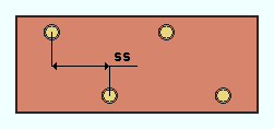
Stud spacing: A distance (in the primary dimension " Units " or other units ). How this distance is applied depends on the " Pattern setting :"

|
ss = " Stud spacing "
" Pattern setting " = ' Fixed ' " Pattern underrun " = ' Left end ' ud = underrun distance lsd = " Left side distance " rsd = " Right side distance " |

|
ss = " Stud spacing "
" Pattern setting " = ' Equal ' lsd = " Left side distance " rsd = " Right side distance " |
When the " Pattern setting " is ' Fixed ' and the " Right... " and " Left Distance " is also ' Fixed ', the studs are spaced at exactly this distance, with any remaining underrun distance placed at the end of the member chosen for the " Pattern underrun ."
When the " Pattern setting " is ' Equal ', the spacing distance is the maximum spacing of the studs.
Pattern underrun: Left end or Right end or Equal Both ends . This applies when the " Pattern setting " is ' Fixed ' and the " Right... " and " Left Distance " is also ' Fixed '. If the length of the beam or column cannot be equally divided by the " Stud spacing ," choosing...

|
" Pattern underrun " =
' Left end ' ud = underrun distance ss = " Stud spacing " lsd = " Left side distance " |

|
" Pattern underrun " =
' Right end ' ud = underrun distance ss = " Stud spacing " rsd = " Right side distance " |

|
" Pattern underrun " =
' Equal Both ends ' ud = underrun distance ss = " Stud spacing " |
' Left end ' places any remaining underrun distance between the last and the second to last stud at the left end of the member. The underrun distance is calculated by the program, and will not exceed the " Stud spacing ."
' Right end ' results in any remaining distance being placed at the right end of the member.
' Equal Both ends ' results in any remaining distance being equally divided between both ends of the member.

|
" Stud column qty " = ' 1 ' |

|
" Stud column qty " = ' 2 ' |
' 1 ' results in a single column of welded studs on the selected beam or column.
' 2 ' adds two columns of studs to the member.
Column distance: The distance (in the primary dimension " Units " or other units ) between stud columns. This applies when the " Stud column qty " is ' 2 '. If " Column distance " is unlocked ( ![]() ), the program selects the distance between the columns.
), the program selects the distance between the columns.

|
cd = " Stud column offset " |
Stud column offset: A distance (in the primary dimension " Units " or other units ) by which the stud column or columns is offset from the center of the member. A positive distance moves the column or columns of studs toward the near side, or, if the studs are on the web of a beam, down.

|
sco = " Stud column offset " |
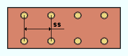
Stud column pattern: Normal or Staggered or Reverse staggered . This applies when the " Stud column qty " is ' 2 '.
| ss = " Stud spacing " | |
|
"Stud column pattern" =
' Normal ' |
|
"Stud column pattern" =
' Staggered ' |

|
"Stud column pattern" =
' Reverse staggered ' |
' Normal ' generates columns of studs in parallel rows.
' Staggered ' staggers the rows by removing alternate studs.
' Reverse staggered ' is similar to ' Staggered ', but the staggering in inverted.
End Settings
Left distance setting: Fixed or Minimum .
' Fixed ' ensures that the " Left start distance " sets the exact distance of the closest stud to the left end of the member from that end.
' Minimum ' ensures that the stud will be placed no greater than the " Left start distance " from the left end of the member.
Note: Setting this to ' Minimum ' eliminates the need for a " Pattern underrun ;" so in that case, the field is disabled ( grayed out ).
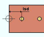
Left start distance: The distance (in the primary dimension " Units " or other units ) from the left end of the member that stud nearest to it is placed. The distance is measured from the center of the stud to the left end. When the " Left distance setting " is ' Minimum ', the start distance is a minumum distance.
|
lsd = " Left start distance " |
Right distance setting: Fixed or Minimum .
' Fixed ' ensures that the " Right start distance " sets the exact distance to the right end of the member from that end.
' Minimum ' ensures that the stud will be placed no greater than the " Left start distance " from the right end of the member.
Note: Setting this to ' Minimum ' eliminates the need for a " Pattern underrun ;" so in that case, the field is disabled ( grayed out ).
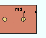
Right start distance: The distance (in the primary dimension " Units " or other units ) from the right end of the member that stud nearest to it is placed. The distance is measured from the center of the stud to the right end. When the " Left distance setting " is ' Minimum ', the start distance is a minumum distance.
|
rsd =
" Right start distance " |
page 1 | contents | model > component > add > | toolbox
------  Weld Settings ------
|
|
If this box is checked (
), the studs are welded to the member.
If the box is not checked (
), no welds are added.
" Weld... " options are available when " ![]() Add weld " is checked.
Add weld " is checked.
Weld class: ' ![]() Shop ' or '
Shop ' or ' ![]() Field '
Field '
'
Shop ' shop welds the studs to the member.
'
Field ' fields welds the studs to the member.
Weld type: Fillet . This sets the " Weld type " on the Weld Edit window in Modeling as well as the " Weld type " for the weld symbol on the member detail.
| symbol | name | weld used for... |
|
|
fillet | General welding of material. |
Weld size: A distance (in the primary dimension " Units " or other units ) that indicates depth of preparation, size or strength of the weld. This sets the " Weld size " on the Weld Edit window in Modeling as well as the " Weld size " for the weld symbol on the member detail.
Weld tailtext: blank or a string of characters . This sets the " Supplementary tail text " on the Weld Edit window in Modeling as well as the " Supplementary tail text " for the weld symbol on the column detail.
|
In this example of a weld symbol, the character string TYP is the tail text. |
If this field is left ' blank ', a tail is not drawn on the weld symbol.
If a ' string of characters ' is entered, a tail with that character string as the tail text is drawn on the weld symbol.
page 1 | contents | model > component > add > | toolbox
------  View Settings ------
If this box is checked (
), and the selected member is a beam, a system-created "TOP VIEW" is added. This view appears in the view list of the " Isolate Member " toolbox and on the beam's detail. The selected member must be a column; otherwise, this setting is ignored.
If the box is not checked (
), no top view is added to a selected beam.
Tip: Such a view is useful if "
Add to Top Flange " is checked, because it cause that top flange to be detailed, showing the studs.
page 1 | contents | model > component > add > | toolbox

