The " OK " button is disabled (grayed out) to indicate a validation error. Hover the " OK " button with your mouse pointer to get a listing of settings you need to change on this window. When all settings are valid, the " OK " button is enabled.
Red-colored highlighting identifies an entry that is invalid. You need to change that setting, or you will not be able to close this window using " OK ."
Warning! Don't make changes to the Bent Plate Material window that you can make on this window, Bent Plate Edit . Most changes made to this miscellaneous member's main material outside of this window will make the member graphical (" Main Material " = ' USER ').
Surfaces Connection (a custom component you can add to a miscellaneous member)
Bent plate member layout :
1 . A bent plate miscellaneous member can be properly located and rotated even in an isometric view. Before adding the member, be aware of the following:
The key to ensuring that a miscellaneous member's material is properly oriented in the model is proper location of the member's work points and proper " Rotation " around the member line established by those work points.
Before adding a bent plate miscellaneous member in Modeling , you should Open ( Ctrl + o ) a view that will facilitate the locating of the work points.
You can adjust the " Elevation " of a bent plate miscellaneous member's work points on its edit window. If you want the elevation of both work points to be at a particular elevation, you may want to open a plan view at the desired elevation.
You may want to add construction lines so that there are INCL points for locating work points.
Custom components such as the Surfaces Connection can be added to miscellaneous members. If you plan to add such a connection to your bent plate miscellaneous member, you need to locate the work points of the member accordingly.
Be aware that you can apply a left- or right-end " Material setback " to set the bent plate material back from its left- or right-end work point in order to accommodate a connection. For example, if your bent plate work point was located using INCM to connect the material to a column, setting the " Material setback " to half the depth of the column would set back the bent plate material to be flush with the column's flange.
2 . To add a bent plate miscellaneous member (in Modeling ):
Alternative 1 : Press F2 > check the box for " Miscellaneous steel " > double-click " Bent Plate ."
Alternative 2 : Choose Model > Member > Prompt for Member Type > double-click " Bent Plate ."
3 .Locate - Repeat - Return mouse bindings become active, and you are prompted to locate the bent plate's work points. Two work points are required to lay out a bent plate.
3b : Left-click ( Locate ) at two different on-screen positions to define the member line between those two points. The first work point you enter when you add the bent plate defines the left end of the member. Both points are represented as exact points after step 4, when the member is actually generated in the model.
The " Length leg 1 " will be perpendicular to the member line between these two points. Provided that the plate is not " Centered " and its " Rotation " is ' -90 ' degrees (the default), one face of leg 1 will be in the work plane of your view.
The first point that you locate is identified by an origin symbol . The origin symbol also tells you which end is the member's left end.
The following illustration shows the difference between laying out work points from left to right versus right to left.
The following illustration shows the difference between laying out these points from top to bottom versus bottom to top in an elevation view.
If you Model > Member > Isolate > ... a bent plate miscellaneous member, you will find that the member's MAIN VIEW shows the member's origin symbol ( ) to be to your left. This is true for any miscellaneous member -- even if the origin symbol for the member is to your right in a plan view. The MAIN VIEW in member isolation directly correlates to the main view of the miscellaneous member's detail.
Best practice when adding a miscellaneous member in a plan view is to input the member from left to right or from bottom to top. That way, when you add a grid line from left to right, the near side of the member, as determined by the location of its left end , will be the side looking toward the bottom or toward the right of the screen.
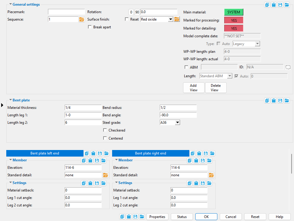
4 . The Bent Plate Edit window opens. On it are settings for the bent plate that you are adding.
4a : Make entries to the " Length leg 1 " and " Length leg 2 " fields to set the length of these legs from the member line to their edges.
4b : Enter a " Bend radius " and a " Bend angle " to set the amount of bending around the member line.
4e : Press the " OK " button at the bottom of the window to apply your settings and close this window.
Note: The default settings on this window are those of the last bent plate miscellaneous member added or edited in this session of Modeling . Even if all you do is double-click a bent plate member and press " OK " on its edit window, its settings become the defaults for the next-added bent plate miscellaneous member. You therefore only need to make changes to those settings which are different for this member.
5 . If User and Site Options > Modeling > " Process after modeling operation " is ' Process and create solids ', the new plate will have automatically undergone all phases of Process and Create Solids and will show up in a solid form . If that option is ' Process ' or ' Do nothing ', then the member line of the bent plate you just added shows up on screen in stick form , and you will have to Process > Process and Create Solids in order to have the member piecemarked and able to be displayed in a solid form. Do one (1) of the following:
bindings
Alternative 1 : Move the mouse pointer ( ) and middle-click ( Repeat ) to lay out a bent plate just like the last one beginning at the point where the point location target ( ) is at. The X, Y global axes location of the repeated plate will begin from the located repeat point (where the target is at). The plate's Z location and other settings will be that of the last-added or last-edited bent plate.
Alternative 2 : Follow these instructions beginning with step 3 to add a bent plate with different settings than the one you just laid out.
Alternative 3 : Right-click ( Return ) if you are done adding bent plate.
------ Bent Plate ------
Material thickness: The thickness of this bent plate (in the primary dimension " Units " or other units or the gage ). The thickness of a " Checkered " plate is measured exclusive of its raised pattern.
To enter gage plate: Type in the ' gage number' followed by ' ga ' (example: ' 4ga ' is rewritten as ' 4GA ' when you Tab out of the field). Right-click tells you the stored thickness (based on industry standards), from which the weight of the gage plate is calculated. Allowable gages are any whole number from 3 to 38 . You can also enter an exact decimal thickness to get the gage (example: ' .1345 ' becomes ' 10GA ' when you Tab out of the field). The " Description " for a gage plate follows the format: ' bent plate prefix ' followed by ' numberGA ' followed by ' x ' followed by ' width ' (example: BPL16GAx15 1/2 ).
Thickness precision: You can enter a plate " Material thickness " that is more precise than the " Dimension precision " that is set at Home > Project Settings > Fabricator > Detailing > Drawing Presentaton . For example, if you enter ' 5/32 ' and the " Dimension precision " is ' 1/16 ', the thickness of the plate will be ' 5/32 '. The thickness you enter will be reflected in the " Description " and will propagate to the bill of material, reports, etc. The setup option to " Round flat plate values " does not affect this. Be aware that the Ruler measures to whatever the " Dimension precision " is set to, which means that the plate's measured thickness may not exactly match its actual thickness.
Note: If you are newly adding this bent plate, the thickness that will be entered to this field by default is the thickness of the last bent plate that was added or edited. How the thickness is measured with respect to the elevation is determined by whether it is " Centered " or not.
The following can be used to track the choice made here when " Main material " is ' SYSTEM ':
Length leg 1: The distance (in the primary dimension " Units " or other units ) measured parallel with leg 1 as shown in cross section from the edge of leg 1 to the member line established in step 3 . This is the length of the leg of the bent plate that remains fixed if you change the " Bend angle ."
Note: Unless you Rotate the member around its Y axis, the leg 1 length dimension is measured perpendicular to the member line established in step 3 . Even if you rotate its material around its Z axis, the leg 1 length dimension will still be measured perpendicular to the length of the member (to its X member axis).
The following can track the choice made here when " Main material " is ' SYSTEM ':
Length leg 2: The distance (in the primary dimension " Units " or other units ) measured parallel with leg 2 as shown in cross section from the edge of leg 2 to the member line established in step 3 . This is the length of the leg of the bent plate that is repositioned if you change the " Bend angle ."
The following can reliably show the choice made here when " Main material " is ' SYSTEM ':
Bend radius: The radius (in the primary dimension " Units " or other units ) of the bend between the two legs. This radius defines the length of bend, but not the bend angle .
Visualizing the bend radius: If you were to extrapolate a circle from the inside curvature of the bend on the bent plate, then the distance from any point on the inside curve of the bend to the center of the circle would be the distance that you would enter to this field.
The following can track the choice made here when " Main material " is ' SYSTEM ':
Bend angle: A positive or negative (-) number of degrees ( 360 to -360 ) defining the angle of the bend in the bent plate.
Note: This angle is measured counterclockwise from a line tangent to the near side surface of leg 2 of the bent plate. It determines the position of a tangent line along the near side surface of leg 1 of the bent plate. Changing the " Bend angle " will reposition leg 2 with respect to leg 1 of the bent plate. Leg 1 will remain fixed.
The following can accurately reveal the choice made here when " Main material " is ' SYSTEM ':
Steel grade: A36 or A572 or etc. This is the grade of steel for the bent plate whose settings are defined on this window.
Setup: If the steel grade you want is not on the list box ( ) for this field, you can use Home > Project Settings > Job > Plate Grades to add it to the list.
The following can be used to track the choice made here when " Main material " is ' SYSTEM ':
If this box is checked ( ), this bent plate becomes a checkered plate, which is a steel plate with raised ribs on its near-side surface to prevent slippage on items such as floors and stair treads. The " Material thickness " of a checkered plate is measured exclusive of the raised pattern. The plate will be detailed on the submaterial and the member with a small sample of the checkered pattern .
If the box is not checked ( ), the bent plate is considered to have a smooth near-side surface.
The following can reveal the choice made here when " Main material " is ' SYSTEM ':
If this box is checked ( ), the bend plate will be centered on the vertex of its bend radius with reference to its work points .
If the box is not checked ( ), the near-side surface of leg 1 of the bent plate will be aligned with the bent plate's work points (if the bent plate was not rotated around the Z axis).
Note: This option does not change a bent plate's left or right " End elevation ."
Bent plate left end settings
Bent plate right end settings
An origin symbol identifies a miscellaneous member's left end when you hover its member line.
----- Member ------
End elevation: The elevation (in the primary dimension " Units " or other units ) of the work point at this end of the bent plate. For a non-sloping plate, both the left and right end elevations are the same. When you add the bent plant, its work points are placed in your current view's reference elevation until you change their elevations here, on this window.
A bent plate has two exact points , whose elevation you can change by changing the plate's left- and/or right-end " End elevation ."
To determine the end elevation on bent plate in the 3D model, use Construction Line Add or a similar tool, select EXPT as the Locate option, then snap the point location target to the work point at the end of the member. The Z coordinate reported in the X-Y-Z display tells you the elevation at the snapped-to exact point.
Tip: You should use this option instead of rotating a bent plate member's material to change its left- or right-end elevation. For complex situations, you can Model > Member > Move/Stretch one or the other of its work points.
Standard detail: None or a standard detail name . To apply a standard detail, you can type in the file name of the drawing (if you know it), or press the "file cabinet" browse button ( ) and double-click any job standard detail or global standard detail that is on the list.
If ' none ' is entered here, then no standard detail will be applied on this end of the miscellaneous member when it is automatically detailed .
If a ' standard detail name ' is entered here, the next time you auto detail this miscellaneous member, the reference point of the standard detail will align with the input work point on this end of the member, and the standard detail's bill of material will be combined with the member's bill of material. The detail is placed on a layer that is named after the standard detail plus a "_L" or "_R" suffix.
------ Settings ------
Material setback: The positive or negative (-) distance in the primary dimensioning " Units " that you want the (left or right) end of the bent plate to be displaced from its work point.
A ' positive material setback ' makes the bent plate shorter. The distance is subtracted from the work point distance.
A ' negative (-) material setback ' makes the bent plate longer. The negative distance is also subtracted from the work point distance.
The following can track the choice made here when " Main material " is ' SYSTEM ':
Leg 1 cut angle: Any positive or negative (-) angle measured in degrees ( 89 to -89 ). The cut is made along leg 1 .
If the left end of the bent plate is to your left on your computer screen and negative distances along its Y member axis are toward the bottom of the screen: ' 0 ' (zero) square cuts the end. A ' positive angle ' is measured counterclockwise from a perpendicular bisector to the member line. A ' negative (-) angle ' is measured clockwise from a perpendicular bisector to the member line.
Leg 2 cut angle: Any positive or negative (-) angle measured in degrees ( 89 to -89 ). The cut is made along leg 2 .
If the left end of the bent plate is to your left on your computer screen and positive distances along its Z member axis are toward the top of the screen: ' 0 ' (zero) square cuts the end. A ' positive angle ' is measured counterclockwise from a perpendicular bisector to the member line. A ' negative (-) angle ' is measured clockwise from a perpendicular bisector to the member line.
 Misc steel " > " Bent Plate ")


 ), the X-Y-Z display , Modeling > Locate options and Offset Controls .

) to be to your left. This is true for any miscellaneous member -- even if the origin symbol for the member is to your right in a plan view. The MAIN VIEW in member isolation directly correlates to the main view of the miscellaneous member's detail.
) and middle-click ( Repeat ) to lay out a bent plate just like the last one beginning at the point where the point location target (
) for this field, you can use Home > Project Settings > Job > Plate Grades to add it to the list.
), the bent plate is considered to have a smooth near-side surface.