 Group Member Edit
- General Settings
- Step-By-Step
- Tips and Tricks
- Related Tools
![]() Copy, Paste, Save, Load buttons:
Copy, Paste, Save, Load buttons:
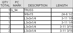
Description: The text string that you want to appear as the " Description " for line 1 in the group member's bill of material.
| " Description " entered here : |
|
|
| " Description " in the bill of material : |
|
Status Display: Group member status > Group description
Report Writer: GroupedMember.Description
System piecemark or User piecemark: A text string of up to 61 characters which identifies this group member. If this is blank when you press " OK ," piecemarking assigns the group a system piecemark.
| System piecemark | The text string entered is the system piecemark that piecemarking has assigned. SDS2 piecemarking is permitted change this mark. |
| User piecemark | Any text string manually entered here is a user piecemark. SDS2 piecemarking will not assign new members that user piecemark, nor will piecemarking remove that user piecemark from members to which it has been assigned. |
Note: This field is disabled if you are editing multiple group members .
Setup: Piecemarking uses the " Piecemark Prefix " for " Group Member " when assigning a system piecemark to a group member. The system piecemarks for component members of group members can optionally be broken apart from non-grouped members using " Break apart sub-member marks when ."
CNC: If you " Download " for CNC and select a group member piecemark, each component member of that group member is downloaded to a separate file named after that component member's piecemark.
Related tools: To rename a system piecemark and keep it a system piecemark, use " Change Marks " (after the member's detail is on a sheet) or " Detail Sheet Autoloading " (as details are placed onto sheets). Or use the " Rename Project Items " utility (at any time). To change a piecemark from system to user or vice-versa, use SDS2 Edit Piecemark Options .
Group members also have index numbers: These index numbers are usually shown in brackets [num] , much like a member number is shown in brackets for a member. Each group member index number in a Job is unique, providing a programmatic way to distinguish group members that have the same piecemark.
Status Display: Group member status > Group piecemark
Report Writer: GroupedMember.Piecemark
Main member: Any member that makes up the group member can be selected as the " Main member ." Initially you select this member when you Create Group Member .
Each member is listed on the list box (
) by its piecemark and member number [in brackets]. The member that you select is the member that preset views are created from when you " Add View " on this window or " Preset " in isolation. For example, if the member you select is the top chord of a truss, and you add a preset "TOP FLANGE" view, the view will be of the top chord of the truss.
Tip: See " Main view locked to main member " to set the member that is selected here to be the "MAIN VIEW" that is shown on the detail and in isolation. Click here for more on creating views for group members.
Piecemark on member: The member that the " System piecemark " or " User piecemark " (entered above ) will be displayed on in a view in Modeling .
The list box (
) for this field lists each member that makes up the group member by its piecemark and member number [in brackets].
Surface finish: None or Sandblasted or Red oxide or Yellow zinc or Gray oxide or Blued steel or Galvanized or Duplex Coating or Undefined 1 or Undefined 2 or Undefined 3 or Red oxide 2 or Any user added surface finish. This applies the surface finish to the sub-members as well as the attached submaterial, with the check box (![]() ) checked on for auto inside of the material edit window. This affects the colors of 'Solid ' members on erection views in the Drawing Editor . This also sets the color when "Output material color " is set to 'Surface finish ' for a VRML Export or a DWG/DXF Export . The "Color " ( not "Surface finish ") sets the color of this material in Modeling .
) checked on for auto inside of the material edit window. This affects the colors of 'Solid ' members on erection views in the Drawing Editor . This also sets the color when "Output material color " is set to 'Surface finish ' for a VRML Export or a DWG/DXF Export . The "Color " ( not "Surface finish ") sets the color of this material in Modeling .
| sand blasted | red oxide | yellow zinc | user surface finish 1 |
| gray oxide | blued steel | galvanized | user surface finish 2 |
To assign a different surface finish, you can drop-down the current surface finish and select the one you want, or you can press the "file cabinet" browse button (
) and double-click any surface finish that is on the list.
Reset : ![]() or
or ![]() .
.
If this box is checked (
), all attached materials surface finish are reset to follow what is selected on the submember level, with the check box (
) checked on for auto inside of the material edit window, when the window is closed by selecting the "OK"button (or the Enter key).
If the box is not checked (
), all attached materials surface finish remains at what is set inside the material edit window.
Note 1: If the member's material surface finish changes from what the group member level has set, an information tag is shown next to the surface finish in the group member edit window. This notifies the user that a member is not following what was set on the group member level.
Note 2: Member Piecemarks can be split apart by surface finish. All surface finishes that do not have the 'Break Marks Member' checked on can be applied to any like member with out the member splitting. If the 'Break Marks Member' is checked on then only like members with that specific surface finish can have the same piecemark.
Tip 1: "Surface area" is reported on the General Information inside the material edit window -- and this can be used to estimate the amount of coating required and its cost.
Tip 2: Changing "Steel grade " "Color " and "Surface finish " do not cause the material to be regenerated. This means that, if you change those settings only, material fit operations such as a Fit Exact may, optionally, be preserved.
Report Writer: MemberMaterial.Material.SurfaceFinish
Setup: Surface Finish Settings
Update Attributes: Surface finish reset:
Update Attributes: Surface finish value:
Sequence: Any sequence name from Home > Project Settings > Job > Modeling > Zone and Sequence > Sequence Names .
To enter a different sequence: You can type in any sequence name that is on the Sequence Names list, or press the "file cabinet" browse button (
) and double-click any sequence name that is on the list.
Entering a sequence assigns that sequence to all members that make up the group member. This applies even if mixed entries are made here.
Warning: If the setup option " Break member piecemarks apart by " in Member and Material Piecemarking is set to ' Sequence ' or ' Zone ', members that make up this group member may be assigned new piecemarks if you change the sequence of this group member. The same is true if the box is checked for " Break submaterial marks apart by sequence " or " Break submaterial marks apart by zone ."
Setup: The Zone and Sequence window.
Topic: Dividing a model into sequences/zones
Tools: Sequence by Area , Set Sequence , Update Attributes
Status Display: General status options > Sequence and Zone
Main view locked to main member: ![]() or
or ![]() .
.
If this box is checked (
) and you select a different " Main member ," then the "MAIN VIEW" of the group member is locked to the newly selected " Main member ." You can rotate that view in isolation .
If the box is not checked (
) and you select a different " Main member ," then the "MAIN VIEW" of the group member remains the member that it was previously locked to.
Tip: If you Isolate Group Member by Location , then press the " Preset " button, the view you create will be based off the " Main member " that is selected. If this box is checked, then you know that view is also the "MAIN VIEW." If this box is not checked, then you know that the preset views will not be based off of the "MAIN VIEW."
Defaults: When you do a Create Group Member , you select the member that you want to be the " Main member ." By default, the box for " Main view locked to main member " is checked, which means that this member is also the "MAIN VIEW" of the group member.
Report Writer: GroupedMember.LockMainViewToMainMember
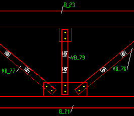
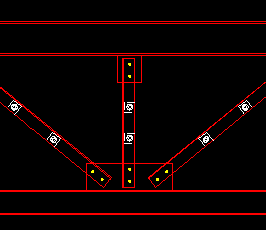
Show member marks on detail: ![]() or
or ![]() . This applies when this group member undergoes Detail Member Groups .
. This applies when this group member undergoes Detail Member Groups .
 |
 |
If this box is checked (
) when you Detail... this group member, Detail Member Groups generates a pointer and a member piecemark label for each member that is part of the group member. Pointers that are directly over the member being called out have a face indicator .
If the box is not checked (
) when you Detail... this group member, the members are not identified on the resulting drawing.
Note: If " Show member marks ... " is checked along with " Show sub material ... " and " Show section sizes ... " then a single pointer to the member main material is used for the main member mark, the submaterial mark and the section size.
Report Writer: GroupedMember.ShowMemberMarkOnDetail
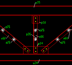
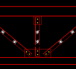
Show sub material marks on detail: ![]() or
or ![]() . This applies when this group member undergoes Detail Member Groups .
. This applies when this group member undergoes Detail Member Groups .
 |
 |
If this box is checked (
) when you Detail... this group member, Detail Member Groups generates a pointer and a material piecemark label for each material that is part of the member group.
If the box is not checked (
) when you Detail... this group member, the submaterials are not identified on the resulting drawing.
Note: If " Show sub material ... " is checked along with " Show member marks ... ', a single pointer and label will be used to identify the member and submaterial mark for each member main material. Only the submaterial mark will be shown on submaterials other than the member main material.
Report Writer: GroupedMember.ShowSubMarkOnDetail
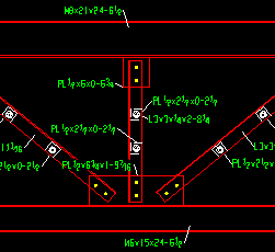
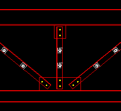
Show section sizes on detail: ![]() or
or ![]() . This applies when this group member undergoes Detail Member Groups .
. This applies when this group member undergoes Detail Member Groups .
 |
 |
If this box is checked (
) when you Detail... this group member, Detail Member Groups generates a pointer and a section size label for each material that is part of the member group.
If the box is not checked (
) when you Detail... this group member, the section sizes are not identified on the resulting drawing.
Note: If " Show section sizes ... " is checked along with " Show sub material ... " and " Show member marks ... " then a single pointer to the member main material is used for the main member mark, the submaterial mark and the section size. For submaterials other that the member main material, the label associated with a pointer will show the submaterial mark and the section size.
Report Writer: GroupedMember.ShowSectionSizeOnDetail
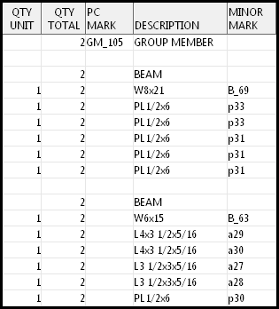
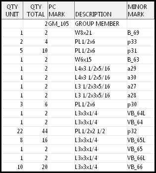
Organize BOM by submember piecemark : ![]() or
or ![]() . BOM stands for bill of material. You can review/edit a group member's bill of material by choosing Objects > Bill of Material > Edit Bill while in the group member's detail. The choice made here will update a group member's BOM when you Process > Detail Member Groups .
. BOM stands for bill of material. You can review/edit a group member's bill of material by choosing Objects > Bill of Material > Edit Bill while in the group member's detail. The choice made here will update a group member's BOM when you Process > Detail Member Groups .
|
||||||
|
Neither of these examples show the entire BOM . They show only the top part. For both BOMs, the setup option " |
If this box is checked (
), the bill of material will be organized by submember, with submaterials, shop bolts and field bolts listed together with their associated submember. This means that submaterials that are otherwise exactly the same may be listed on separate lines. The bill will likely be much longer.
If the box is not checked (
), then submaterials that are the same will be listed on a single line, regardless of whether or not they are associated with more than one submember. Consequently, the bill of material will require fewer lines to enumerate the same number of parts.
Marked for processing: ![]() or
or ![]() or
or ![]() .
.
means that all members that make up this group member will automatically be selected the next time you Process and Create Solids . All submembers of a group member are automatically marked for Process and Create Solids whenever you Create Group Member or Ungroup Group Member or when you check the box for "
Galvanized ." To make this read " NO, " close this window and Process and Create Solids , then open this window again.
means that all members that make up this group member have undergone Process and Create Solids and have not since that time been interactively or automatically marked for processing.
indicates mixed entries to this field. It means that some members that make up this group need to undergo Process and Create Solids , but other members do not.
Marked for detailing: ![]() or
or ![]() . If this button said " NO " when you first opened this window, you can switch it to " YES " and thus mark this group member for detailing. You can also switch from " YES " to " NO " as long as a detail already exists.
. If this button said " NO " when you first opened this window, you can switch it to " YES " and thus mark this group member for detailing. You can also switch from " YES " to " NO " as long as a detail already exists.
means this group member will automatically be selected for detailing the next time you Detail Member Groups . All members whose details have not yet be generated or which have been altered in Modeling since the time that their details were generated are automatically marked for detailing.
means that the member has undergone Detail Member Groups and has not been altered in Modeling since that time. OR it means that the user has switched this button to " NO " to prevent an existing detail from being detailed again. Another way to make this read " NO " is to press the " Detail Member " button on this window.
Report Writer: GroupedMember.NeedsToBeDetailed
| Special Buttons for Detailing this Group Member Note: Preset views are based off of the " Main member ." |
|||
|
|
|
|
|
| This button opens a window with a list of preset views that you can select. When you Detail this group member, each preset view is drawn on the detail. | This button opens a list of views that you can delete. If this group member has only a main view, you get a warning instead of a list of views since you cannot delete the main view. | This button details this group member. Newly added views are drawn on the detail. Deleted views are not drawn. | Press this button to start up the Drawing Editor . You will automatically be shown the detail of this group member if this group member has been detailed. |
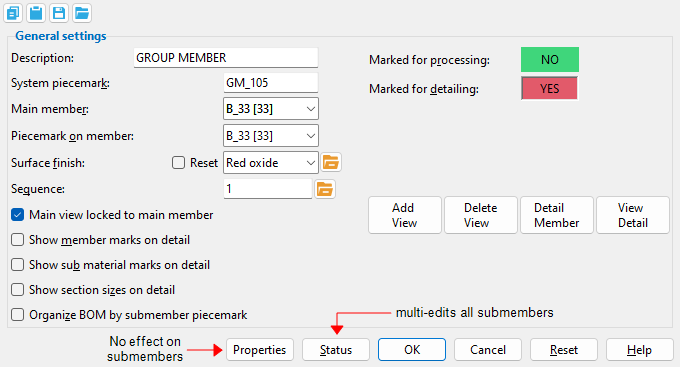
"Properties" opens the Edit Properties window, on which you can make entries to custom properties . If your current Job was set to use a legacy flavor when it was created, the window that opens is named Custom Properties , not Edit Properties . The properties that you set affect the group member only, they do not affect submembers.
Tip: The Edit Properties window can also be used to read "
Log " entries or review or type "
Notes ."
Tip: The Group Member Properties command is an alternative to this button. It opens the Edit Properties window directly, without your first having to open a group member edit window.
" Status " opens the Member Status Review window, which can give you additional information about the status of all submembers in this group. You can use to enter status information or designate a member as an existing member . Any change you make to a group member's status is inherited by all submembers.
Note: This button shows
if one or more " Repeat " check boxes on the Member Status Review window do not match the checked-unchecked state of same-named fields in User and Site Options > Site > " Member status items to copy/repeat ." On the Status Review window, the fields that do not match User and Site Options are plotted in red .
" OK " (or the Enter key) closes the edit window and saves any changes you have made on the window to the member file.
Solids on "OK" : If the appropriate choice is made to User and Site Options > Modeling > " Automatically process after modeling operation ," then this member will automatically be regenerated (Create Solids will take place) after your press " OK ." Otherwise, you will have to manually Process and Create Solids in order for changes you made on this window to be fully updated in the 3D model.
Change all: If you Edit Member (one member only) and make a change that potentially triggers the " Do you want to change all ... " dialog and the 3D model contains more than one member of the same type that has the same piecemark as the member you changed, a yes-no dialog opens. On it is the question, " Do you want to change all (members with this piecemark). " Press the " Yes " button to change all the members; press the " No " button to change only this member.
" Cancel " (or the Esc key or the ![]() button) closes the edit window without saving any changes that you have made. " Cancel " does not undo a " Detail Member " operation.
button) closes the edit window without saving any changes that you have made. " Cancel " does not undo a " Detail Member " operation.
Note: If you opened this window while adding a member, " Cancel " brings you back to the work point location step of adding a member.
Tip: Any time you use Edit Member just to review a member (and you do not want to set the defaults for to-be-added members), the best way to close this window is to " Cancel. "
" Reset " undoes any changes made since you opened this window.
Exception: " Reset " does not undo changes made using the " Add View " " Delete View " " Detail Member " " View detail " buttons.
1 . Invoke Group Member Edit using the Find Tool by searching the command name and clicking the icon, which is pictured above.
Learn more about alternative methods for launching commands.
2 . The status line prompts you to "Locate group members to edit". Select one or more group members, then press the Enter key or right-click and choose OK on the context menu.
3 . The group member edit window opens. When you are done making changes to the settings in the group member's edit window, click the OK button to accept the changes.
Alternative: Click the Cancel button to not apply any changes made to the settings in the group member edit window and end the command.
- Detail Member Groups (affected by options on this window)
- Grayed out fields (indicate mixed entries or that the field is disabled)
- Use member mark for main material in shop bill of group member ( Home > Project Settings > Fabricator > Mem & Mtrl Piecemarking > " Group " tab > )
- Status Display ( Member Status > Grouped member )
