Sag Rod (Legacy) Member
- General Overview
- Step-By-Step
- Tips and Tricks
- Related Tools
![]() Copy, Paste, Save, Load buttons:
Copy, Paste, Save, Load buttons:
- The position of these "form" buttons on the window tells you what settings they apply to. Click here for more information.
- You can
 Copy the settings on this window, then
  Paste those settings to a different edit window of the same type.
- You can
 Save the settings on this window to a file stored in a global folder that is used by your current version of SDS2. Give the file a name that will help other users identify its purpose. You can
  Load a saved file to replace the settings on this window (except Piecemark) with the settings that are stored in the file you select.
- When editing multiple windows at the same time, Paste and Load replace mixed entries to a single field with a single entry. Copy and Save ignore fields with mixed entries, treating them as if they have no entry or do not exist.
Model complete date: **NOT SET** or a month day year.
Graphical: ![]() or
or  . Click here for more information.
If this box is checked
( , GTP Export can output layout point data from a Sag Rod (Legacy) member for GTP software.)
If the box is not checked
( , GTP Export cannot output layout point data for that Sag Rod (Legacy) member.)
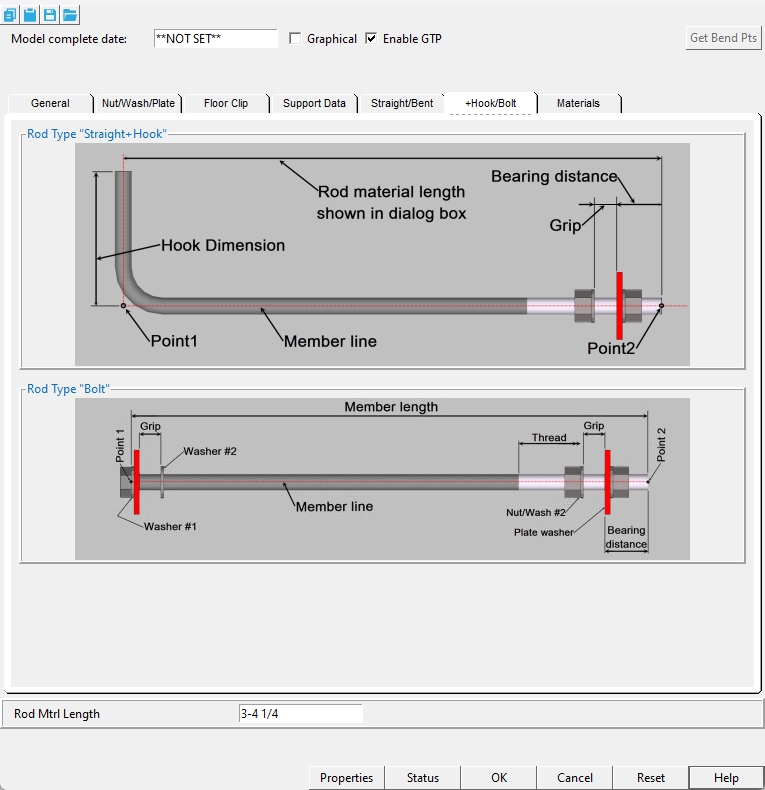
Get Bend Pts: Pressing this button gives you the option to reset or remove the bend point location(s) of a bent rod type.
Rod Mtrl Length: This is the material length of the round bar material.
Properties opens the Edit Properties window, on which you can make entries to custom properties. If your current Job was set to use a legacy flavor when it was created, the window that opens is named Custom Properties , not Edit Properties.
Tip: The Edit Properties window can also be used to read
Log entries or review or type
Tip: The Member Properties command is an alternative to this button. It opens the Edit Properties window directly, without your first having to open a member edit window.
Status opens the Member Status Review window, which can give you additional information about the member, and which you can use to enter status information or designate a member as an existing member.
Note: This button shows
if one or more Repeat check boxes on the Member Status Review window do not match the checked-unchecked state of same-named fields in User and Site Options > Site > Member status items to copy/repeat. On the Status Review window, the fields that do not match User and Site Options are plotted in red .
OK (or the Enter key) closes the edit window and saves any changes you have made on the window to the member file.
Solids on OK: If the appropriate choice is made to User and Site Options > Modeling > Automatically process after modeling operation, then this member will automatically be regenerated (Create Solids will take place) after your press OK. Otherwise, you will have to manually Process and Create Solids in order for changes you made on this window to be fully updated in the 3D model.
Change all: If you Edit Member (one member only) and make a change that potentially triggers the Do you want to change all ... dialog and the 3D model contains more than one member of the same type that has the same piecemark as the member you changed, a yes-no dialog opens. On it is the question, Do you want to change all (members with this piecemark). Press the Yes button to change all the members; press the No button to change only this member.
Cancel (or the Esc key or the ![]() button) closes the edit window without saving any changes that you have made. Cancel does not undo a Detail Member operation.
button) closes the edit window without saving any changes that you have made. Cancel does not undo a Detail Member operation.
Note: If you opened this window while adding a member, Cancel brings you back to the work point location step of adding a member.
Tip: Any time you use Edit Member just to review a member (and you do not want to set the defaults for to-be-added members), the best way to close this window is to Cancel.
Reset undoes any changes made since you opened this window.
Exception: Reset does not undo changes made using the Add View, Delete View, Detail Member, and View detail buttons.
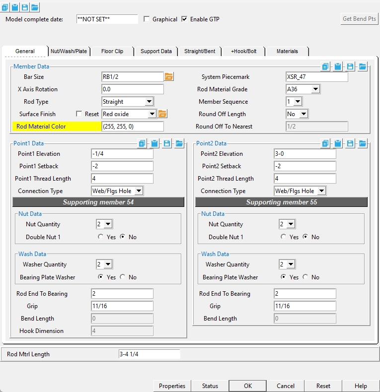
General > Member Data
Bar Size: Any round bar material section size that is maintained in the local shape file can be entered here. You can type in the section size or press the file cabinet browse button (  ) and select it from the list that opens.
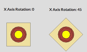
X Axis Rotation: The angle (in degrees) that the whole member is rotated about the member line.
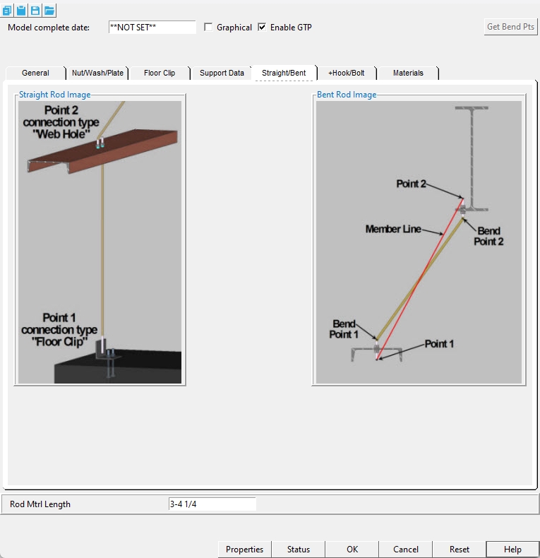
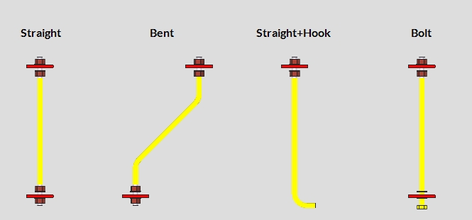
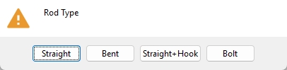
Rod Type: Straight or Bent or Straight+Hook or Bolt.
Note: When the Rod Type is changed to 'Bent' after the sag rod member has been added, you will be prompted to add bends to the rod.
Bend Point 1 : The status line prompts "Locate Bend Point 1 or RETURN". Move your mouse pointer
( to place the point location target)
( where you want, then left-click (Locate) the bend at the Point 1 end of the Sag Rod (Legacy) member.)
Alternative: Right-click (Return) or press the Esc button to not add a bend to the Point 1 end of the sag rod.
Bend Point 2 : The status line prompts "Locate Bend Point 2 or RETURN". Move your mouse pointer
( to place the point location target( where you want, then left-click (Locate) the bend at the Point 2 end of the Sag Rod (Legacy) member.Alternative: Right-click (Return) or press the Esc button to not add a bend to the Point 2 end of the sag rod.
Surface finish: None or Sandblasted or Red oxide or Yellow zinc or Gray oxide or Blued steel or Galvanized or Duplex Coating or Undefined 1 or Undefined 2 or Undefined 3 or Red oxide 2 or Any user added surface finish. This affects the colors of Solid members on erection views in the Drawing Editor . This also sets the color when Output material color is set to Surface finish for a VRML Export or a DWG/DXF Export. The Color (not Surface finish) sets the color of this material in Modeling .
| sand blasted | red oxide | yellow zinc | user surface finish 1 |
| gray oxide | blued steel | galvanized | user surface finish 2 |
To assign a different surface finish, you can drop-down the current surface finish and select the one you want, or you can press the
Auto ![]() or
or ![]()
If this box
If the box
Note 1: Submaterial piecemarks can be split apart by surface finish. All surface finishes that do not have the Break Marks Material checked on can be applied to any like material with out the material splitting. If the Break Marks Material is checked on then only like materials with that specific surface finish can have the same piecemark, and because the submaterial marks differ so would the member's piecemark.
Note 2: When exporting a KISS file using "model" as the Data source surface finish data on the materials are compiled into the KISS download as follows, with a few exceptions (G=galvanized, N= none or sandblasted, P= others). Those exceptions are:
If the box for Finish routing in KISS export setup is set to a user routing
If the user has adjusted the Abbreviation for any of the default provided surface finishes
If you are using a user added surface finish
In these cases you will get what is provided in either the User routing, or the abbreviation field. For other exports it will always provide the abbreviation in the 'surface finishes' settings page.
Tip 1: Surface area is reported on the General Information window -- and this can be used to estimate the amount of coating required and its cost.
Tip 2: Changing Steel grade, Color, and Surface finish do not cause the plate to be regenerated. This means that, if you change those settings only, material fit operations such as a Fit Exact may optionally be preserved.
Report Writer: MemberMaterial.Material.SurfaceFinish
Setup: Surface Finish Settings
Rod Material Color: This sets the color of the round bar material. You can type in the RGB color code or right-click inside the entry field and select either the "Color Dialog" option or select a pre-defined color from the "Named Colors" list.
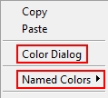
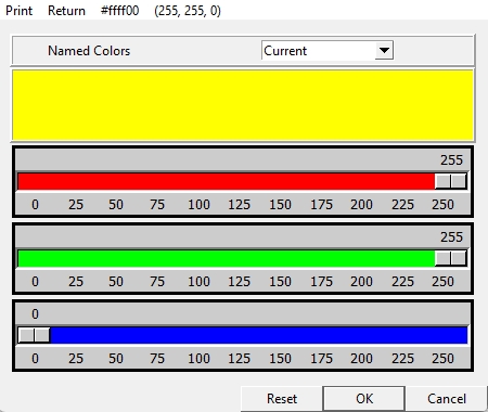
Color Dialog window: Select a pre-defined color from the "Named Colors" list or use the RGB sliders to set the color.
System Piecemark: A text string of up to 61 characters which identifies this member as having a unique design distinct from other members that have been assigned different piecemarks.
Rod Material Grade: A36 or A572-50 or etc. This sets the steel grade of the round bar material.
Member Sequence: Any sequence name from the Sequence Names list can be entered here.
Defaults: The sequence assigned by default to the first Sag Rod (Legacy) member that is added after you first start up Modeling is the sequence listed in line 1 of the Sequence Names list. The default sequence for each subsequently added Sag Rod (Legacy) member during the same session in Modeling becomes the sequence assigned to the last-added or last-edited Sag Rod (Legacy) member.
To assign a different sequence, you can click the list box
( and select any sequence name that is on the list.)
Round Off Length: Yes or No. When "Yes" is selected, the "Rod Material Length" is rounded up or down based on the values of "Round Off To Nearest" and the "Rod Material Length".
Round Off To Nearest: The dimensional value entered here is applied when "Round Off Length" is set to "Yes". When "Round Off Length" is set to "No", this setting is disabled.
General > Point1/Point2 Data
Point1/Point2 Elevation: The elevation of the sag rod's work points.
Note: Depending on setback values, the work points of the sag rod might not be at the exact ends of the sag rod's round bar material. The work points are the two locations selected when inputting the member.
Point1/Point2 Setback: A positive or negative (-) distance the sag rod will be displaced from its work point.
A 'positive setback' makes the sag rod shorter. The distance is subtracted from the "Rod Mtrl Length".
A 'negative (-) setback' makes the sag rod longer. The distance is added to the "Rod Mtrl Length".
Point1/Point2 Thread Length: The distance from the end of the sag rod to where the threading ends.
Connection Type: Plain or Web/Flgs Hole or Web Hole or Bott Flg Hole or Top Flg Hole or Floor Clip.
Plain: Does not add a hole to the supporting member at this end of the sag rod.
Web/Flgs Hole: Adds a hole to the supporting member's web or flange at this end of the sag rod.
Web Hole: Adds a hole to the supporting member's web.
Bott Flg Hole: Adds a hole to the supporting member's bottom flange.
Top Flg Hole: Adds a hole to the supporting member's top flange.
Floor Clip: Adds a clip angle to this end of the sag rod. A Floor Clip connection can only be applied to the Point1 end of the sag rod.
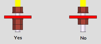
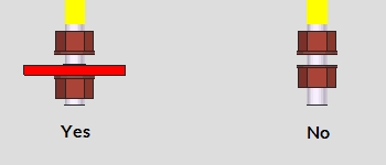
Bearing Plate Washer: 
 Yes or No.
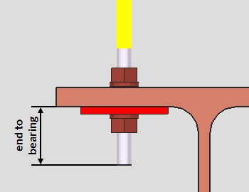
Rod End To Bearing: The distance from the end of the sag rod to the location where the sag rod connection bears on the supporting member.
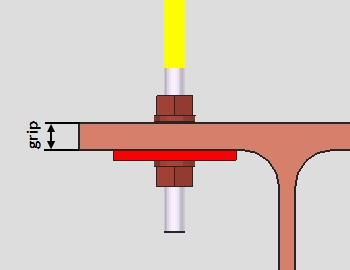
Grip: The distance between washers (or between nuts if washers are omitted) where the rod passes through the supporting material. The value entered here typically equals the thickness of the supporting material(s) the rod connects to.
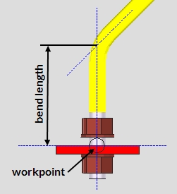
Bend Length: The distance from the sag rod's work point to the center of the bend in the rod. This measurement is taken along the center of the round bar material. This applies when the "Rod Type" is set to 'Bent'.
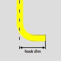
Hook Dimension: The distance from the center of the sag rod to the end of the hook. This applies when the "Rod Type" is set to 'Straight+Hook'.
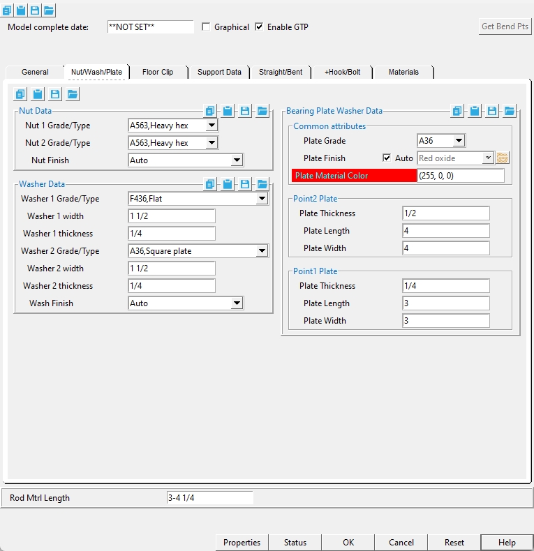
Nut/Wash/Plate > Nut Data
Nut 1/Nut 2 Grade/Type: A563, Heavy hex or A5630C, Heavy hex or A563-DH, Heavy hex or A194, Heavy hex.
Setup: The options listed here are populated from Home > Project Settings > Job > Bolts, Washers, and Holes > Nut and Washer Schedule > Nuts tab.
Nut Finish: Auto or Black or Mechanically galvanized or Hot dipped galvanized.
Nut/Wash/Plate > Washer Data
Washer 1/Washer 2 Grade/Type: F436, Hardened or F436, Flat or F436, Bevel, etc.
Setup: The options listed here are populated from Home > Project Settings > Job > Bolts, Washers, and Holes > Nut and Washer Schedule > Washers tab.
Washer 1/Washer 2 width: The width and length of a square washer, or the diameter of a round plate washer. This option is only enabled when the washer grade/type is set to flat, square plate, or round plate.
Washer 1/Washer 2 thickness: The thickness of a square or round plate washer. This option is only enabled when the washer grade/type is set to flat, square plate, or round plate.

Wash Finish: Auto or Black or Mechanically galvanized or Hot dipped galvanized.
Nut/Wash/Plate > Bearing Plate Washer Data > Common Attributes
Plate Grade: A36 or A572-42 or A572-50 or A588.
Setup: The options listed here are populated from Home > Project Settings > Job > Material Grades > Plate Grades.
Plate Finish: None or Sandblasted or Red oxide or Yellow zinc or Gray oxide or Blued steel or Galvanized or Duplex Coating or Undefined 1 or Undefined 2 or Undefined 3 or Red oxide 2 or Any user added surface finish. This affects the colors of 'Solid ' members on erection views in the Drawing Editor . This also sets the color when "Output material color " is set to 'Surface finish ' for a VRML Export or a DWG/DXF Export . The "Color " ( not "Surface finish ") sets the color of this material in Modeling .
| sand blasted | red oxide | yellow zinc | user surface finish 1 |
| gray oxide | blued steel | galvanized | user surface finish 2 |
To assign a different surface finish, you can drop-down the current surface finish and select the one you want, or you can press the "file cabinet" browse button (
Auto
If this box is checked (
If the box is not checked (
Note 1: Submaterial piecemarks can be split apart by surface finish. All surface finishes that do not have the 'Break Marks Material' checked on can be applied to any like material with out the material splitting. If the 'Break Marks Material' is checked on then only like materials with that specific surface finish can have the same piecemark, and because the submaterial marks differ so would the member's piecemark.
Note 2: When exporting a KISS file using "model" as the "Data source" surface finish data on the materials are compiled into the KISS download as follows, with a few exceptions (G=galvanized, N= none or sandblasted, P= others). Those exceptions are:
If the box for "Finish" routing in KISS export setup is set to a user routing
If the user has adjusted the Abbreviation for any of the default provided surface finishes
If you are using a user added surface finish
In these cases you will get what is provided in either the User routing, or the abbreviation field. For other exports it will always provide the abbreviation in the 'surface finishes' settings page.
Tip 1: "Surface area" is reported on the General Information window -- and this can be used to estimate the amount of coating required and its cost.
Tip 2: Changing "Steel grade " "Color " and "Surface finish " do not cause the plate to be regenerated. This means that, if you change those settings only, material fit operations such as a Fit Exact may, optionally, be preserved.
Report Writer:MemberMaterial.Material.SurfaceFinish
Setup:Surface Finish Settings
Plate Material Color: This sets the color of the rectangular plate material. You can type in the RGB color code or right-click inside the entry field and select either the "Color Dialog" option or select a pre-defined color from the "Named Colors" list.
Color Dialog window: Select a pre-defined color from the "Named Colors" list or use the RGB sliders to set the color.
Nut/Wash/Plate > Bearing Plate Washer Data > Point1/Point2 Plate
Plate Thickness: The material thickness of the rectangular plate material that makes the bearing plate washer.
Plate Length: The workpoint distance of the rectangular plate material that makes the bearing plate washer.
Plate Width: The material width of the rectangular plate material that makes the bearing plate washer.
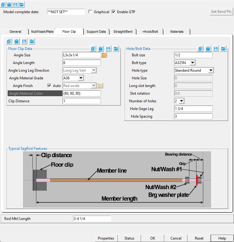
Floor Clip > Floor Clip Data
Angle Size: Any angle material section size that is maintained in the local shape file can be entered here. You can type in the section size or press the file cabinet browse button ( ) and select it from the list that opens.
Angle Length: The workpoint distance of the angle rolled section material that makes the floor clip.
Angle Long Leg Direction: Long Leg Vert or Long Leg Horiz. The direction the long leg of the angle rolled section material is oriented to when the section size has unequal leg lengths. This setting is disabled when the angle's section size has even leg lengths.
Angle Material Grade: A36 or A572-50 or A588.
Setup: The options listed here are populated from Home > Project Settings > Job > Material Grades > Angle Grades.
Angle Finish: None or Sandblasted or Red oxide or Yellow zinc or Gray oxide or Blued steel or Galvanized or Duplex Coating or Undefined 1 or Undefined 2 or Undefined 3 or Red oxide 2 or Any user added surface finish. This affects the colors of 'Solid ' members on erection views in the Drawing Editor . This also sets the color when "Output material color " is set to 'Surface finish ' for a VRML Export or a DWG/DXF Export . The "Color " ( not "Surface finish ") sets the color of this material in Modeling .
| sand blasted | red oxide | yellow zinc | user surface finish 1 |
| gray oxide | blued steel | galvanized | user surface finish 2 |
To assign a different surface finish, you can drop-down the current surface finish and select the one you want, or you can press the "file cabinet" browse button (
Auto
If this box is checked (
If the box is not checked (
Note 1:Submaterial piecemarks can be split apart by surface finish. All surface finishes that do not have the 'Break Marks Material' checked on can be applied to any like material with out the material splitting. If the 'Break Marks Material' is checked on then only like materials with that specific surface finish can have the same piecemark, and because the submaterial marks differ so would the member's piecemark.
Note 2: When exporting a KISS file using "model" as the "Data source" surface finish data on the materials are compiled into the KISS download as follows, with a few exceptions (G=galvanized, N= none or sandblasted, P= others). Those exceptions are:
If the box for "Finish" routing in KISS export setup is set to a user routing
If the user has adjusted the Abbreviation for any of the default provided surface finishes
If you are using a user added surface finish
In these cases you will get what is provided in either the User routing, or the abbreviation field. For other exports it will always provide the abbreviation in the 'surface finishes' settings page.
Tip 1: "Surface area" is reported on the General Information window -- and this can be used to estimate the amount of coating required and its cost.
Tip 2: Changing "Steel grade " "Color " and "Surface finish " do not cause the plate to be regenerated. This means that, if you change those settings only, material fit operations such as a Fit Exact may, optionally, be preserved.
Report Writer:MemberMaterial.Material.SurfaceFinish
Setup:Surface Finish Settings
Angle Material Color: This sets the color of the angle rolled section material. You can type in the RGB color code or right-click inside the entry field and select either the "Color Dialog" option or select a pre-defined color from the "Named Colors" list.
Color Dialog window: Select a pre-defined color from the "Named Colors" list or use the RGB sliders to set the color.
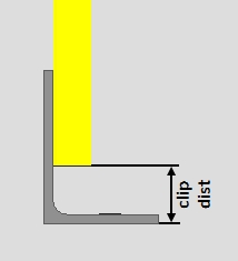
Clip Distance: The distance the heel of the angle rolled section material is located from the end of the sag rod.
Floor Clip > Hole/Bolt Data
Bolt size: The diameter of the shank of the theoretical bolt that would be used to anchor the floor clip to it's supporting material (3D bolts are not actually added to the floor clip). This setting automatically determines the "Hole Size" based on the requirements of your project's "Connection design method" when the "Hole Type" is set to either 'Standard Round', 'Short Slot', 'Oversized round', or 'Long Slot'.
Bolt type: A325N, A325SC, A325X, A490N, etc.
Setup: The options listed here are populated from Home > Project Settings > Job > Bolts, Washers, and Holes > Bolt Specifications.
Hole type: Standard Round or Short Slot or Oversized round or Long Slot or Anchor Bolt Hole or Cope Hole or Erection Pin Hole or Plug Weld Hole.

Hole Size: The diameter of the hole. This setting is enabled when "Hole type" is set to 'Anchor Bolt Hole', 'Cope Hole', 'Erection Pin Hole', or 'Plug Weld Hole'. When this setting is disabled, the hole's diameter is automatically determined by the value entered for "Bolt size" and the requirements of your project's "Connection design method".
Long slot length: The length of a long slot hole. This setting is only enabled when "Hole type" is set to 'Long Slot'.

Slot rotation: The angle (in degrees) that the slot is rotated relative to its hole group rotation. Slot rotations can be modeled to a precision of 0.1 degree. This setting is only enabled when "Hole type" is set to 'Short Slot' or 'Long Slot'.
when the hole group X axis
is horizontal
when the hole group X axis
is vertical
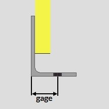
Hole Gage Leg: The distance from the heel of the angle rolled section material to the center of the hole.
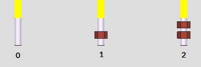
Hole Spacing: The distance between the center of each hole when "Number of holes" is set to '2'.
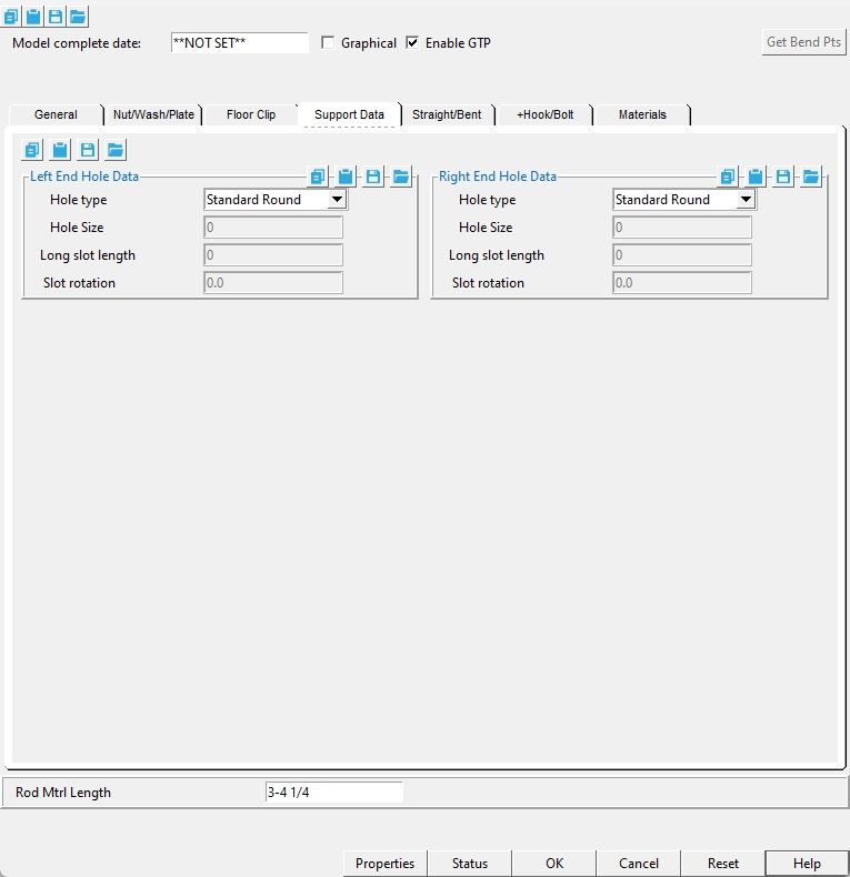
Support Data > Left/Right End Hole Data
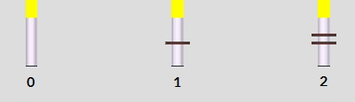
Hole type: Standard Round or Short Slot or Oversized round or Long Slot or Anchor Bolt Hole or Cope Hole or Erection Pin Hole or Plug Weld Hole. This applies to the hole that gets added to the sag rod's supporting member.
Hole size: The diameter of the hole that gets added to the sag rod's supporting member. This setting is enabled when "Hole type" is set to 'Anchor Bolt Hole', 'Cope Hole', 'Erection Pin Hole', or 'Plug Weld Hole'. When this setting is disabled, the hole's diameter is automatically determined by the value entered for "Bar Size" (the round bar material's diameter) and the requirements of your project's "Connection design method".
Long slot length: The length of a long slot hole. This setting is only enabled when "Hole type" is set to 'Long Slot'.
Slot rotation: The angle (in degrees) that the slot is rotated relative to its hole group rotation. Slot rotations can be modeled to a precision of 0.1 degree. This setting is only enabled when "Hole type" is set to 'Short Slot' or 'Long Slot'.
when the hole group X axis
is horizontal
when the hole group X axis
is vertical
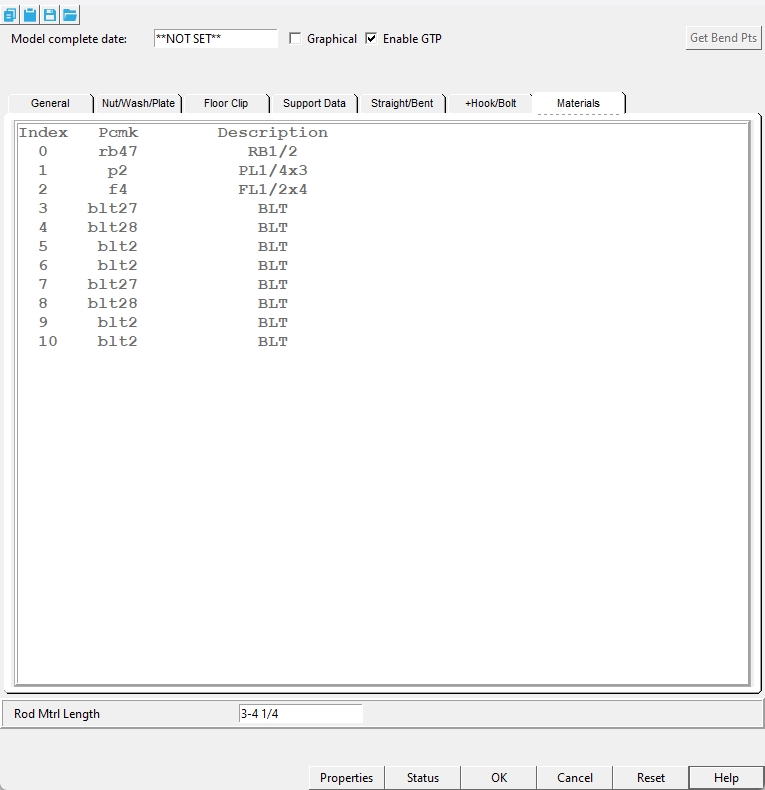
Materials
Pcmk: A list of the submaterial piecemarks for all materials attached to the sag rod member.
Description: A list of each submaterial's description.
1 . Invoke Sag Rod (Legacy) using the Find Tool by searching the command name and clicking the icon, which is pictured above.
Learn more about alternative methods for launching commands.
2 . The status line prompts, "SagRod.Add Point 1". Move your mouse pointer ![]() )
)![]() )
)
Alternative: Right-click (Return) or press the Esc button to end the operation.
3 .The status line prompts, "SagRod.Add Point 2". Move your mouse pointer ![]() )
)![]() )
)
Alternative: Right-click (Return) or press the Esc button to end the operation.
4 . The Rod Type window appears with four buttons: Straight or Bent or Straight+Hook or Bolt. Left-click on a rod type option.
Bent: Follow these additional steps when the Bent option is selected as the Rod Type:
4a . The status line prompts "Locate Bend Point 1 or RETURN". Move your mouse pointer
( to place the point location target( where you want, then left-click (Locate) the bend at the Point 1 end of the Sag Rod (Legacy) member.Alternative: Right-click (Return) or press the Esc button to not add a bend to the Point 1 end of the sag rod.
4b . The status line prompts "Locate Bend Point 2 or RETURN". Move your mouse pointer
( to place the point location target( where you want, then left-click (Locate) the bend at the Point 1 end of the Sag Rod (Legacy) member.Alternative: Right-click (Return) or press the Esc button to not add a bend to the Point 2 end of the sag rod.
5 . The Sag Rod member edit window opens. After you are done changing or reviewing settings, left-click on the 'OK' button.
Alternative: Left-click the 'Cancel' button to end the operation and stop the Sag Rod (Legacy) member from being added to the model.
6 . The status line prompts "SagRod.Add Point 1". Repeat steps 2-5 to add another Sag Rod (Legacy) member.
Alternative: Right-click (Return) or press the Esc button to end the operation.
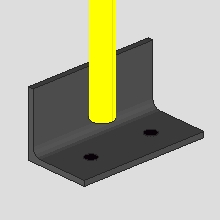
- The sag rod custom member can add holes to members:
- A sag rod can be added in space without a connecting member.
-
Two work points are required to add a sag rod. The two points can be in vertical, horizontal or diagonal alignment.
-
Note in the examples below that the point 1 end is the bottom end. Be aware that if point 1 was the top end, the hook for the 'Straight hook' type would be on the top end, and the bolt head at the bottom end of the "Bolt" type would be at the top end, and so on.
- This following example shows how to get a proper view for one situation. The same principles that are used in this example may apply to many different situations:
|
Suppose that you want to add a sag rod that puts holes in the center of the webs of these two toe-down channel girts, which are in perfect vertical alignment. |
|
Snap to a vertical surface of one of the girts. In this example, the outside surface of the near side toe of the bottom girt is snapped to. |
|
Use View > Relative Depth to move the work plane of your current view into the view depth by a value equal to half the depth of the girt. For this example, the Depth check "Out" distance was also adjusted. |
|
Now, when you add a sag rod and locate -- for example -- an INCM point, that point will be at half the depth of the girt. |