Plate Layout Edit window
( Modeling > F2 > "  Misc steel " > " Plate Layout ")
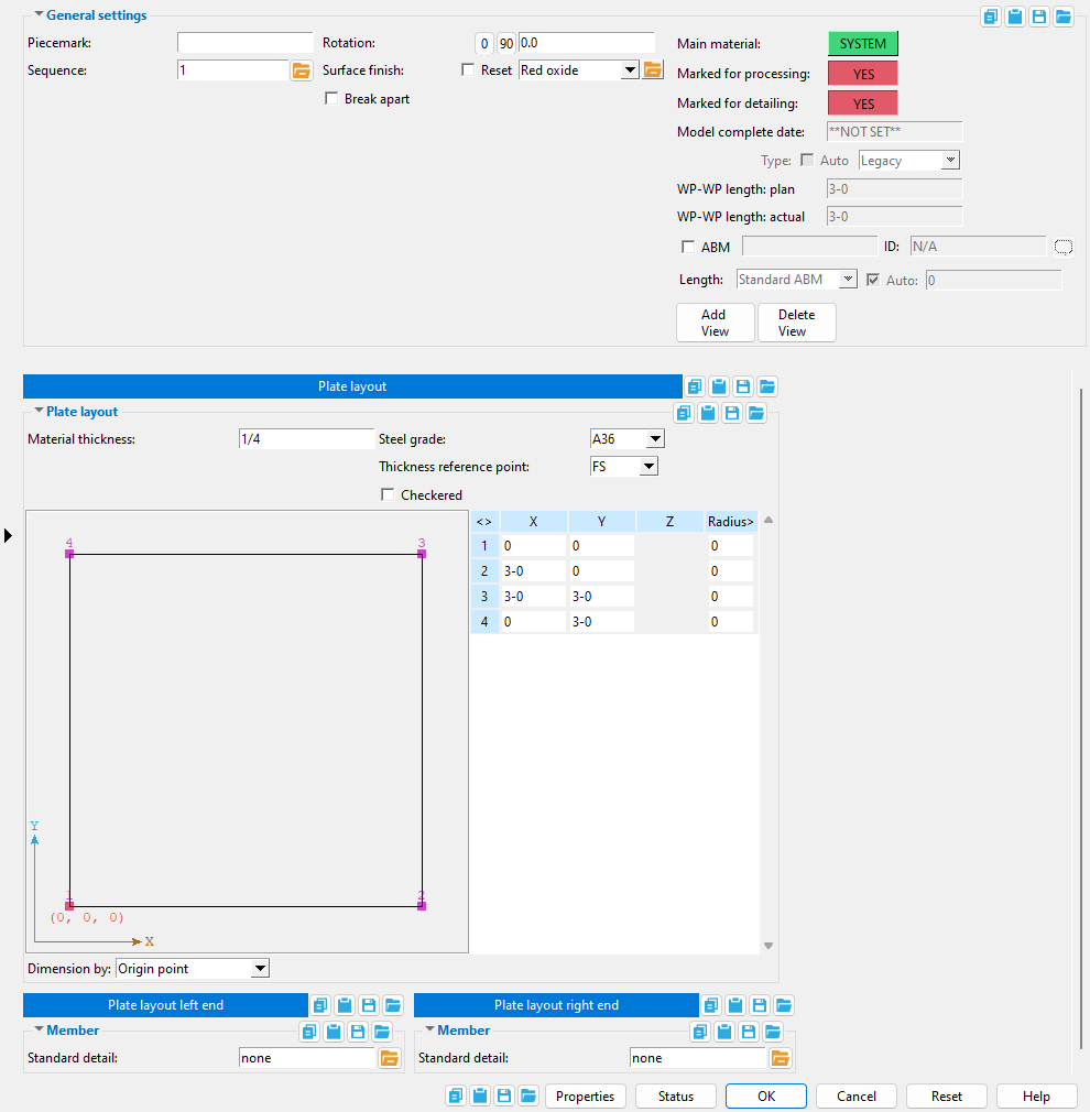
Selecting " Plate Layout " as the " Miscellaneous steel " type adds a custom member with plate layout material to a 3D model.
The Plate Layout custom member is a superior alternative to " Miscellaneous -- Flat Plate Layout ."
The edit window of this member features material and member options on the same window. Its " General settings " include "" Break apart " and " Rotation ," which are not available for the legacy miscellaneous member.


The " OK " button is disabled (grayed out) to indicate a validation error. Hover the " OK " button with your mouse pointer to get a listing of settings you need to change on this window. When all settings are valid, the " OK " button is enabled. 
Red-colored highlighting identifies an entry that is invalid. You need to change that setting, or you will not be able to close this window using " OK ."
Also see :
- Material Types (topic)
- Miscellaneous member types (the complete list)
- Custom members (a plate layout miscellaneous member is a custom member)
- Multi-Sided Flat Plate Material (window can set Plate Layout Edit 's " Main Material " to ' USER ')
- Miscellaneous members versus legacy miscellaneous members (topic)
- Surfaces Connection (a custom component you can add to a miscellaneous member)
Add plate layout :
1 . A plate layout miscellaneous member can be properly located and rotated even in an isometric view. Before adding the member, be aware of the following:
2 . To add a plate layout miscellaneous member (in Modeling ):
Alternative 1 : Press F2 > check the box for "
Alternative 2 : Choose Model > Member > Prompt for Member Type > check the box for "
3 . Locate - Repeat - Return mouse bindings become active, and you are prompted to locate the plate's work points. Three or more work points are required to lay out a plate.
|
|
|
bindings |
3a : Select the appropriate Locate option.
3b : Left-click ( Locate ) at two different on-screen positions to define the member line between those two points. The first work point you enter when you add the layout defines the left end of the member. Both points are represented as exact points after step 4, when the member is actually generated in the model.

The first point that you locate is identified by an origin symbol . The origin symbol also tells you which end is the member's left end. The following illustration shows work points for a multi-sided flat plate laid out in a plan view.
If you Model > Member > Isolate > ... a plate layout miscellaneous member, you will find that the member's MAIN VIEW shows the member's origin symbol (
) to be to your left. This is true for any miscellaneous member -- even if the origin symbol for the member is to your right in a plan view. The MAIN VIEW in member isolation directly correlates to the main view of the miscellaneous member's detail.
Best practice when adding a miscellaneous member in a plan view is to input the first two work points from left to right or from bottom to top. That way, when you add a grid line from left to right, the near side of the member, as determined by the location of its left end , will be the side looking toward the bottom or toward the right of the screen.
3c : A dialog box for corner rounding opens. As you left-click ( Locate ) to define points, remember to set corner rounding for the most recently located point before you left-click ( Locate ) to define the next point. Below is an example of a multi-sided flat plate with and without corner rounding.
3d ( optional ): If you accidentally left-click ( Locate ) at a point you do not want, hold down Shift and left-click ( Remove ) to remove that point. You can remove as many points as you like, then continue locating points as described in 3c.
3e : Middle-click ( Complete ) with your mouse pointer anywhere in the view. This locates the final point exactly where you placed the starting point.
4 . The Plate Layout Edit window opens. On it are settings for the plate layout that you are adding.
4a : " Material thickness " and " Steel grade " and " Thickness reference point " and " Checkered " are filled out with default settings that match the last multi-sided flat plate that you added or edited in your current Modeling session. If you did not previously add or edit such a plate, default settings populate this window. You should change these settings as you see fit, then press the " OK " button.
Tip: The near side of the multi-sided flat plate is the face of the plate you were looking at in the view in which you added the plate (unless you rotated around the Y or Z axes). You can use the " Thickness reference point " option to set whether the thickness of the plate is on the near side, far side or center of the plate.
Note: The default settings on this window are those of the last plate layout miscellaneous member added or edited in this session of Modeling . Even if all you do is double-click such a member and press " OK " on its edit window, its settings become the defaults for the next-added plate layout miscellaneous member. You therefore only need to make changes to those settings which are different for this member.
5 . If User and Site Options > Modeling > " Process after modeling operation " is ' Process and create solids ', the new bent plate layout will have automatically undergone all phases of Process and Create Solids and will show up in a solid form . If that option is ' Process ' or ' Do nothing ', then the member line of the layout you just added shows up on screen in stick form , and you will have to Process > Process and Create Solids in order to have the member piecemarked and able to be displayed in a solid form. Do one (1) of the following:
|
|
|
bindings |
Alternative 1 : Move the mouse pointer (
) and middle-click ( Repeat ) to lay out a flat plate just like the last one beginning at the point where the point location target (
) is at. The X, Y global axes location of the repeated plate will begin from the located repeat point (where the target is at). The plate's Z location and other settings will be that of the last-added or last-edited flat plate.
Alternative 2 : Follow these instructions beginning with step 3 to add a flat plate with different settings than the one you just laid out.
Alternative 3 : Right-click ( Return ) if you are done adding bent plate.
------ Plate layout ------
Material thickness: The thickness of this multi-sided flat plate (in the primary dimension " Units " or other units or the gage ). The thickness of a " Checkered " plate is measured exclusive of its raised pattern. The thickness of the plate is its dimension along its Z member axis , which is perpendicular to the plane on which the plate's " Thickness reference point " is located.
|
The entry made here will also change the " Material thickness " entry in the Multi-Sided Flat Plate Material window if you edit this member's material. |
To enter gage plate: Type in the ' gage number' followed by ' ga ' (example: ' 4ga ' is rewritten as ' 4GA ' when you Tab out of the field). Right-click tells you the stored thickness (based on industry standards), from which the weight of the gage plate is calculated. Allowable gages are any whole number from 3 to 38 . You can also enter an exact decimal thickness to get the gage (example: ' .1345 ' becomes ' 10GA ' when you Tab out of the field). The " Description " for a gage plate follows the format: ' plate type prefix ' + ' numberGA ' + ' x ' + ' diameter ' (example: PL16GAx15 1/2 ).
Thickness precision: You can enter a plate " Material thickness " that is more precise than the " Dimension precision " that is set at Home > Project Settings > Fabricator > Detailing > Drawing Presentaton . For example, if you enter ' 5/32 ' and the " Dimension precision " is ' 1/16 ', the thickness of the plate will be ' 5/32 '. The thickness you enter will be reflected in the " Description " and will propagate to the bill of material, reports, etc. The setup option to " Round flat plate values " does not affect this. Be aware that the Ruler measures to whatever the " Dimension precision " is set to, which means that the plate's measured thickness may not exactly match its actual thickness.
The following can be used to track the choice made here when " Main material " is ' SYSTEM ':
Status Display: Material status > Material plate thickness
Report Writer: XXXXX . Thickness
Advanced Selection: Thickness
Parametric module: Thickness
Steel grade: A36 or A572 or etc. This is the grade of steel for the multi-sided flat plate whose settings are defined on this window.
Setup: If the steel grade you want is not on the list box (
) for this field, you can use Home > Project Settings > Job > Plate Grades to add it to the list.
The following can track the choice made here when " Main material " is ' SYSTEM ':
Report Writer: MemberMaterial.Material.SubMaterial.MaterialGradeDescription
Advanced Selection: MaterialGrade
Parametric module: MaterialGrade
Thickness reference point: FS or Center or NS . Work points for the following three examples are all laid out in a counterclockwise direction at an elevation of 100 feet.Editing a plate layout and changing its " Thickness reference point " will update that member in the 3D model when you press " OK ."
|
' NS ' stands for near side. If you want the plate layout's near side to be at the elevation of the plate's work points, then select ' NS '. The near side is the face you are looking at when the left end of the plate layout is to your left and the right end of the member is to your right. If you added the plate layout in a plan view, the near side is the face that you see in that view.
' FS ' stands for far side. If you want the plate's far side at the elevation of the plate's work points, then select ' FS '. The far side is the face that is away from you when the left end of the plate layout is to your left and the right end is to your right.
Select ' Center ' if you want the thickness of the plate centered at the elevation of plate's work points.
The following can reliably track the choice made here when " Main material " is ' SYSTEM ':
Advanced Selection: MaterialOriginPoint
Parametric module: MaterialOriginPoint
If this box is checked (
If the box is not checked (
), the plate is considered to have a smooth near-side surface.
The following can track the choice made here when " Main material " is ' SYSTEM ':
Report Writer: XXXXX . CheckeredPlatePattern
Advanced Selection: CheckeredPlatePattern
Parametric module: CheckeredPlatePattern
------ Diagram ------
 |
Radius: A distance (in the primary dimension " Units " or other units ) that defines the amount of corner rounding that takes place.
" Radius " is the radius of a circle. Two lines that are tangent to that circle meet at the located point. The arc of the rounded corner ends at the points of tangency of these two lines. 
A " Radius " of ' 0 ' designates a sharp corner with no corner rounding.
Increasing the size of the " Radius " moves the edge of the rounded corner back from the corner point. This is because the " Radius " defines a circle that is tangent to both lines to the corner point. The arc of the rounded corner begins and ends at the tangent points.
You can set a different " Radius " for each corner. Clicking on the upper-right corner of the table (" Radius ") lets you set the radius for each point to be the same value.
Dimension by: Length and angle or Previous point or Origin point . This applies when you hover a point in the diagram with your mouse pointer ( ![]() ), regardless of whether or not you are adding points.
), regardless of whether or not you are adding points.
' Length and angle ' shows one or two dimensions and an angle. The dimension(s) are to the point you are hovering. One dimension may be to the previous point, and another dimension may be to the next point. The angle to the point you are hovering may be the included angle between the hovered point and the previous two points. Or it may be the angle between the hovered point and a horizontal or vertical bisector to the previous point.
' Previous point ' shows horizontal and/or vertical dimensions between the point you are hovering and the previous point in the diagram. Dimensions of zero will not be shown.
' Origin point ' shows horizontal and/or vertical dimensions from the origin point (point 1) to the point you are hovering. Dimensions of zero will not be shown.
Adding points: You can click a line in the diagram to add a point. The new point snaps to your mouse pointer until you left-click to locate that point or right-click to cancel. Dimensions are shown as you move your mouse pointer to reposition the snapped-to point. An alternative to clicking in the diagram to add points is to enter the points to the table.
|
|
----- Member ------
Standard detail: None or a standard detail name . To apply a standard detail, you can type in the file name of the drawing (if you know it), or press the "file cabinet" browse button ( ![]() ) and double-click any job standard detail or global standard detail that is on the list.
) and double-click any job standard detail or global standard detail that is on the list.
If ' none ' is entered here, then no standard detail will be applied on this end of the miscellaneous member when it is automatically detailed .
If a ' standard detail name ' is entered here, the next time you auto detail this miscellaneous member, the reference point of the standard detail will align with the input work point on this end of the member, and the standard detail's bill of material will be combined with the member's bill of material. The detail is placed on a layer that is named after the standard detail plus a "_L" or "_R" suffix.

