 Add Outrigger ( Modeling )
Tool summary :
|
|
Also see :
- Modeling (where custom components can be added)
- Custom components (topic)
- Outrigger Setup ( Home > Project Settings > Job > [ Plugin Defaults } > Components )
- Copy Component (to copy the outriggers to another beam)
- Move Component (to move the outriggers to another beam)
- Explode Component (to reduce the component to its constituent materials and welds)
- Component Selection Tool (to search for custom components of a selected type)
- Model Tree (to find custom components and select them for deletion, editing, etc.)
![]() To add, edit or delete an Outrigger custom component :
To add, edit or delete an Outrigger custom component :
|
Tip: If you use in-tool selection -- that is, select the beam after selecting " Outrigger " as the custom component you want to add -- only wide flange or welded plate wide flange beams will be selectable.
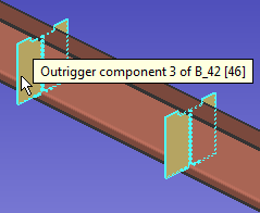
Selecting any material or weld that is part of an Outrigger custom component selects the entire component when the " Selection filter " is set to ' Default ' or ' All ' or ' Custom Components '',
![]() Outrigger custom component settings :
Outrigger custom component settings :
![]() Graphical --------------------------------------------------------------------------------------
Graphical --------------------------------------------------------------------------------------
Graphical : ![]() or
or ![]() .
.
- An Outrigger component is automatically set to "
 Graphical " whenever you make graphical changes to any of its materials. For example, when you Edit Material or perform a material cutting operation on an Outriggers material. This stops the component from being changed during Process and Create Solids . Click here for more information.
- Instead of allowing the component to be made " Graphical ." you may wish to Explode Component .
![]() Locate ------------------------------------------------------------------------------------------
Locate ------------------------------------------------------------------------------------------
Placement method: Pick points or Auto spacing or Fixed spacing .
' Pick points ' lets you locate outriggers by picking points along the beam work line . If you choose to ' Pick points ', you need to be in an appropriate view before you invoke Add Component . A plan view at the beam's left and right " End elevation " works well for a non-sloping beam. For a sloping beam, you should Snap to Surface on the beam's top flange. You may also want to lay out construction lines so that there are INCL or INCM points where you want to locate the outriggers.
After you press " OK " on the Outriggers window, the status line will prompt you to locate points. 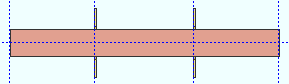
The outriggers are generated at the center of the points that you located. ' Auto spacing ' makes the " Maximum spacing " a maximum. The " Distance from left end to 1st outrigger " and " Distance from right end to 1st outrigger " are fixed. The " X distance " from the left end of the beam material is recorded for each outrigger.
' Fixed spacing ' makes the distances entered for " Distance from left to nearest outrigger " and the " Distance from right to nearest outrigger " into minimums, and the distance entered for " Maximum spacing " into the actual, fixed spacing that is used.
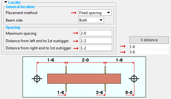
Beam side: Near side or Both or Far side .
|
| The left end of the beam is shown in all three of these examples. |
' Near Side ' places the outriggers on the near side of the beam's web. If you are looking at the web of a beam, and the left end of the beam is to your left, then you are looking at the near side web of the beam.
' Both ' places the outriggers on both the near side and far side of the beam.
' Far Side ' places the outriggers on the far side of the beam's web.
Orientation: Normal or Vertical .
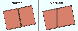
' Normal ' orients the outriggers normal to the beam. That is, the outriggers will be perpendicular to the beam's flanges.
' Vertical ' orients the outriggers vertically.
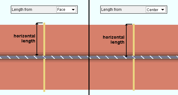
Length from: Face or Center . This sets the reference point that the " Horizontal length " is measured from.
|
| Plate outriggers on both sides of a beam web. The view is taken from beneath the top flange of the beam. |
' Face ' instructs Outrigger to measure the " Horizontal length " from the face of the beam. As a consequence, the " Order length " of a plate outrigger will match the " Horizontal length " value that is entered. The " Order length " of a rolled section outrigger will also match the " Horizontal length " value that is entered.
' Center ' instructs the Outrigger custom component to measure the " Horizontal length " from the center line of the beam.
Spacing
If this box is checked (
If the box is not checked (
), then Process and Create Solids may change the " X distance " values that are shown in order to apply the settings related to the " Placement method " that is specified on this window. You can manually change the " X distance " values since they will be enabled (not grayed out).
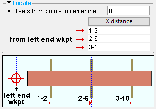
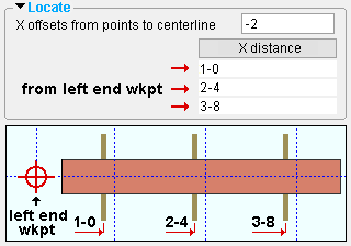
X offsets from points to centerline: A positive (+) or negative (-) distance (in the primary dimension " Units " or other units ). This applies regardless of the " Placement method ." If the spacing between the outriggers is correct, but you want to shift each outrigger a certain distance to the right or to the left, you can enter that positive or negative distance here.
|
|
| To create these examples, the " X offsets from points to centerline " was changed from ' 0 ' to ' -2 '. When the beam was processed, the outriggers shifted 2 inches toward the left of the beam. |
' 0 ' results in no adjustment to the " X distance " locations of the outriggers.
' a positive (+) distance ' adds the distance that is entered to each of the " X distance " locations of the outriggers. As a result, all of the outriggers will shift the entered offset distance away from the left end of the beam.
' a negative (-) distance ' subtracts the distance that is entered to each of the " X distance " locations of the outriggers. As a result, all of the outriggers will shift the entered offset distance toward the left end of the beam.
Maximum spacing: A distance (in the primary dimension " Units " or other units ).This applies when the " Placement method " is ' Auto spacing ' or ' Fixed spacing '.
When the " Placement method " is ' Auto spacing, ' " Maximum spacing " is a maximum.
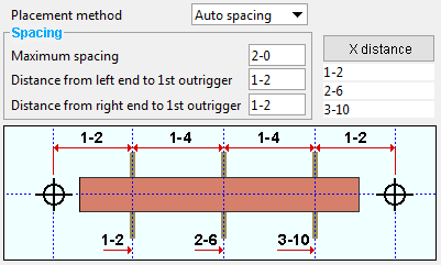
|
The actual spacing may be less than the " Maximum spacing " when the " Placement method " is ' Auto spacing '. In this example, the " Maximum spacing " is 2'-0", while the actual spacing is 1'-4". One outrigger is placed at the " Distance from left end to 1st outrigger ." Another outrigger is placed at the " Distance from right end to 1st outrigger ." |
When the " Placement method " is ' Fixed spacing ', " Maximum spacing " is fixed.
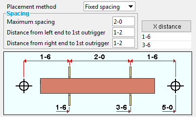
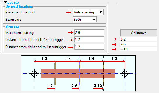
|
The actual spacing will equal the " Maximum spacing " when the " Placement method " is ' Fixed spacing '. In this example, the " Maximum spacing " is 2'-0", and the actual spacing is 2'-0". Note that the " Distance from left end to 1st outrigger ." and the " Distance from right end to 1st outrigger " are not fixed values. |
Distance from left end to 1st outrigger: A distance (in the primary dimension " Units " or other units ). This distance is measured from the left-end workpoint of the beam.
When the " Placement method " is ' Auto spacing, ' an outrigger will be placed the " Distance from left end to 1st outrigger ." Another outrigger will be placed at the " Distance from right end to 1st outrigger ." Additional outriggers will be placed in the space between the nearest-to-the-two-ends outriggers if that space is greater than the " Maximum spacing ."
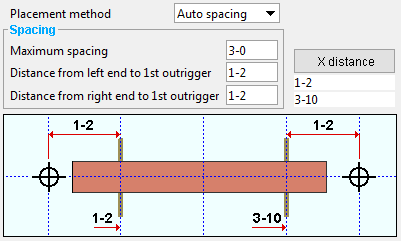
In this example, one outrigger is placed at the " Distance from left end to 1st outrigger ." Another outrigger is placed at the " Distance from right end to 1st outrigger ."
Since the " Maximum spacing " is larger than the space that is available between the outside outriggers, no outrigger is placed in between them.
When the " Placement method " is ' Fixed spacing ', the " Distance from left end to 1st outrigger " is a minimum. No outrigger will be placed closer to the left end than this distance. Outriggers that are the " Maximum spacing " apart from one another will be placed in the available space between the " Distance from left end ... " and " Distance from right end .... " If the " Maximum spacing " exceeds that available space, an outrigger will be placed at the center of that available space.
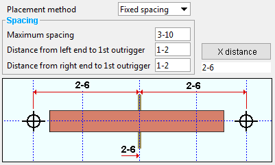
In this example, a near-side and far-side outrigger is placed half-way between the " Distance from left end to 1st outrigger " and the " Distance from right end to 1st outrigger ." This is done because the " Maximum spacing " is larger than the space that is available between the distances from the ends..
Also see the examples that are shown for " Maximum spacing "
Distance from right end to 1st outrigger: See " Distance from left end to 1st outrigger ." This distance-entry field works the same way as that one, except that the distance is measured from the right-end workpoint of the beam.
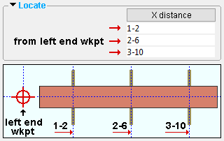
X distance: A table that is filled out after the Outrigger custom component undergoes Process and Create Solids . The table tells you the positioning points of the outriggers from the left end workpoint of the beam. The values reported in the table are editable (i.e., you can type in different X distances), but you must check the box for " ![]() Lock spacing values " if you want to keep Process and Create Solids from changing the values.
Lock spacing values " if you want to keep Process and Create Solids from changing the values.
|
Be aware that the " X distance " reported for an outrigger positioning point is from the workpoint of the beam. Also, the " X distance " locates the center of the thickness of a plate outrigger. It locates the heel of a channel or angle outrigger. It locates the center of a wide flange, W tee, HSS rectangular or HSS round outrigger. |
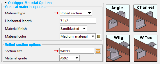
![]() Outrigger material options --------------------------------------------------------------
Outrigger material options --------------------------------------------------------------
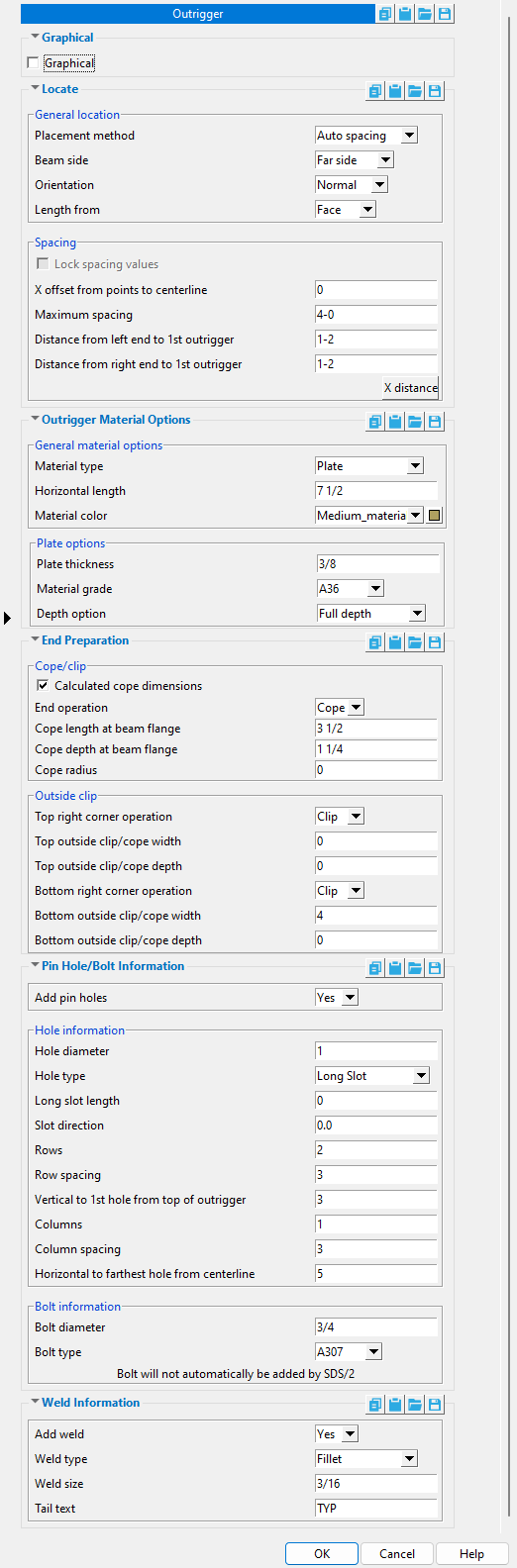
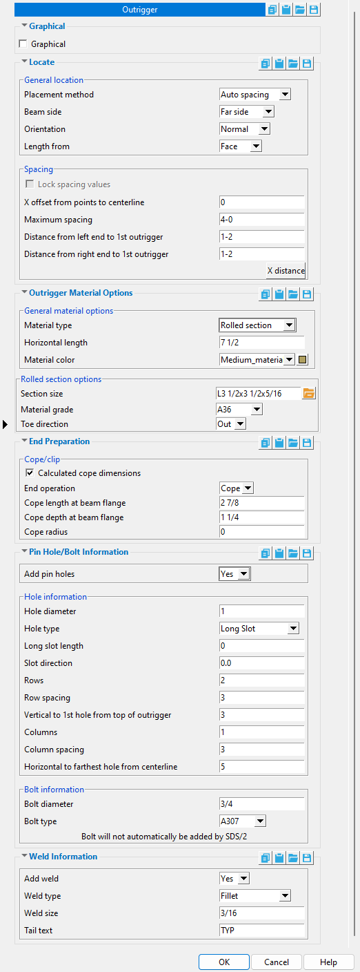
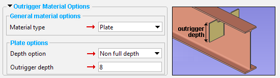
Material type: Plate or Rolled section .
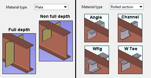
' Plate ' gives you a " Depth option " of ' Full depth ' or ' Non full depth ." If you choose ' Non full depth ', you need to specify the " Outrigger depth ."
' Rolled section ' lets you specify an angle, channel, wide flange, W tee, pipe or HSS/TS as the " Section size " that the outrigger will be fabricated from.
Horizontal length: A distance (in the primary dimension " Units " or other units ). This distance is measured from the ' Face ' of the web or the ' Center ' of the web, depending on the choice made to " Length from ." It is measured perpendicular to the web, which means that it is measured horizontally if the beam web is vertical.
|
|
| Plate outriggers on both sides of a beam web. The view is taken from beneath the top flange of the beam. |
Material color: A predefined color or a custom color . This is the approximate color of the outriggers when the beam it is a submaterial of is displayed in one of the three solid forms . When the " Material type " is ' Plate ', this is the " Color " of the rectangular plate material that the outrigger is fabricated from. When the " Material type " is ' Rolled Section ', this is the " Color " of the wide flange, channel, angle, W tee, HSS rectangular or HSS round section.
The predefined colors are set up on the Predefined Colors window. The color swatch next to the list box (
) displays the color that is selected.
Select ' Custom Color ' (last choice on the list) to launch your operating system's color picker and define any color you like.
Plate options
Plate thickness: The thickness of each of the plate outriggers (in the primary dimension " Units " or other units ). This is also The " Material thickness " of the rectangular plate material that each plate outrigger is made of. This applies only when the " Material type " is ' Plate '.
Material grade: A36 or A572 or etc. This is the grade of steel for plate outriggers. This is also the " Steel grade " of the rectangular plate material that each plate outrigger is made of. To get plate outriggers, the " Material type " must be set to ' Plate '.
Setup: If the grade of steel you want is not shown on the list box (
Depth option: Full depth or Non full depth . This applies when the outrigger " Material type " is ' Plate '.
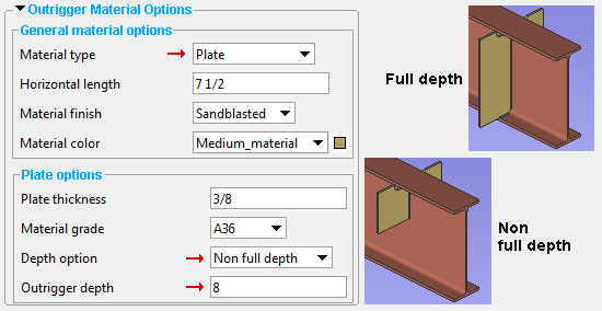
' Full depth ' instructs Outrigger to create plate outriggers that are the full depth of the beam.
' Non full depth ' instructs the Outrigger custom component to create outrigger plates that are the " Outrigger depth " that is specified (below).
Outrigger depth: A distance (in the primary dimension " Units " or other units ). This distance is measured from the inside of the top flange of the beam, parallel with the depth of the beam. It applies when the " Material type " is ' Plate ' and the " Depth option " is ' Non full depth '. It sets the " Material width " on the Rectangular Plate Material window for the plate.
Rolled section options
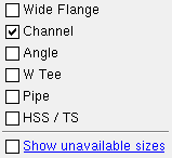
Section size: Any section for W , L , C , HSS round (pipe) , HSS rectangular (tube) or WT material that is listed in the local shape file . You must enter a section size in order to complete a Add Material or Add Miscellaneous Member operation.
C15x50

The selection dialog that opens when you press the button. In this example, only "
To enter a section size: Either type in the section size that you want, or press the "file cabinet" browse button (
Material grade: A36 or A572 or etc. This is the steel grade for the " Section size " entered above. It applies when the outrigger " Material type " is ' Rolled section '.
Setup: If the grade of steel you want is not shown on the list box (
Toe direction: In or Out . This applies when an angle or a channel has been entered as the " Section size ."
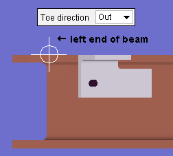
|
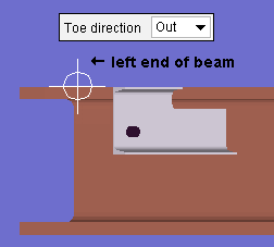
|
| An angle outrigger is shown in the left example. A channel outrigger is shown in the right example. | |
' In ' signifies toe in. When facing the near side of the beam, the left end of the beam will be on your left, and the toes of the channel or the toe of the angle will point toward the left end.
' Out ' signifies toe out. When facing the near side of the beam, the left end of the beam will be on your left, and the toes of the channel or the toe of the angle will point toward the right end.
![]() End preparations --------------------------------------------------------------------------
End preparations --------------------------------------------------------------------------
Calculated cope dimensions: ![]() or
or ![]() . This applies when the " End operation " is ' Cope '.
. This applies when the " End operation " is ' Cope '.
If this box is checked (
If the box is not checked (
End operation: Cope or Fit or None .
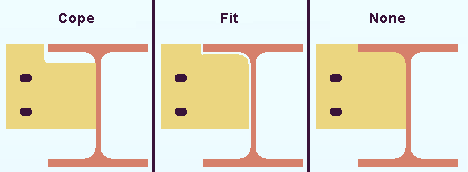
' Cope ' copes the outrigger with automatically calculated settings for " Cope length at beam flange " and " Cope depth at beam flange " when "
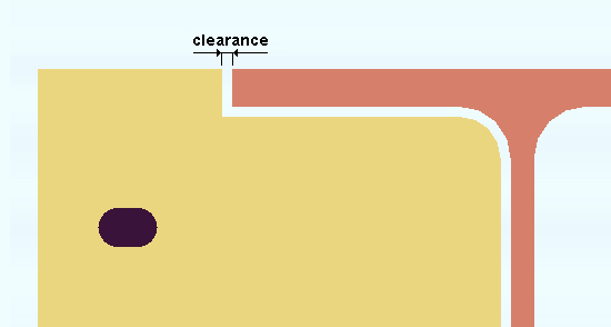
' Fit ' cuts the outrigger to the profile of the beam with an option to set the " Clearance " between the two.
' None ' results in no cut. The outrigger will likely clash with the beam flange.
" Cope length at beam flange " or " User cope length at beam flange ": The distance (in the primary dimension " Units " or other units ) that the beam-side, top of the outrigger will be coped parallel to the flange of the beam.
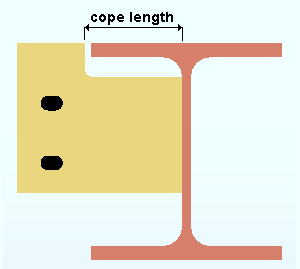
" Cope length at beam flange " indicates that "
" User cope length at beam flange " indicates that "
" Cope depth at beam flange " or " User cope depth at beam flange ": The distance (in the primary dimension " Units " or other units ) that the beam-side, top of the outrigger will be coped parallel to the depth of the beam.
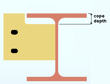
" Cope depth at beam flange " indicates that "
" User cope depth at beam flange " indicates that "
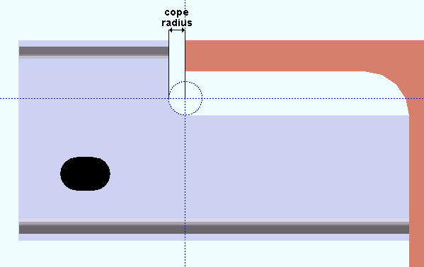
Cope radius: The distance (in the primary dimension " Units " or other units ) that is the radius of the circular corner cut of a cope. This applies when the outrigger " Material type " is ' Rolled section '. It sets the " Cope radius " on the Rolled Section Material window.
Clearance: The distance (in the primary dimension " Units " or other units ) between the outline of the outrigger and the profile of the beam when ' Fit ' is the " End operation "
Outside clip
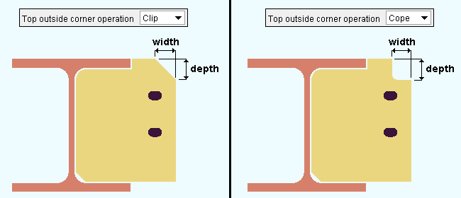
Top right corner operation: Clip or Cope . This applies when the " Material type " is ' Plate '.
|
| If you are looking at the a near-side outrigger from the left end of the beam, the top, outside corner will be the top, right corner. |
' Clip ' gives you options for " Top outside clip/cope width " and a " Top outside clip/cope depth " so that you can specify a straight, angular cut. You must enter values other than ' 0 ' to those fields in order for the top, outside corner of the plate outrigger to be clipped.
' Cope ' gives you options for " Top outside clip/cope width " and a " Top outside clip/cope depth " so that you can specify a 90 degree, L-shaped cut. You must enter values other than ' 0 ' to those fields in order for the top, outside corner of the plate outrigger to be coped.
Top outside clip/cope width: The distance (in the primary dimension " Units " or other units ) that the outside, top corner of the plate outrigger will be coped or clipped parallel to the beam flange width.
Top outside clip/cope depth: The distance (in the primary dimension " Units " or other units ) that the outside, top corner of the plate outrigger will be coped or clipped parallel to the beam depth.
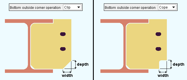
Bottom right corner operation: Clip or Cope . This applies when the " Material type " is ' Plate '.
|
| If you are looking at the a near-side outrigger from the left end of the beam, the bottom, outside corner will be the bottom, right corner. |
' Clip ' gives you options for " Bottom outside clip/cope width " and " Bottom outside clip/cope depth " so that you can specify a straight, angular cut. You must enter values other than ' 0 ' to those fields in order to get a clip cut.
' Cope ' gives you options for " Bottom outside clip/cope width " and a " Bottom outside clip/cope depth " so that you can specify a 90 degree, L-shaped cut. You must enter values other than ' 0 ' to those fields in order for the bottom, outside corner of the plate outrigger to be coped.
Bottom outside clip/cope width: The distance (in the primary dimension " Units " or other units ) that the outside, bottom corner of the plate outrigger will be coped or clipped parallel to the beam flange width.
Bottom outside clip/cope depth: The distance (in the primary dimension " Units " or other units ) that the outside, bottom corner of the plate outrigger will be coped or clipped parallel to the beam depth.
![]() Pin Hole/Bolt Information --------------------------------------------------------------
Pin Hole/Bolt Information --------------------------------------------------------------
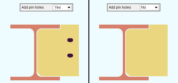
' Yes ' instructs Outrigger to allow the adding of pin holes. Options such as " Hole diameter ," " Hole type ," etc. are enabled.
' No ' instructs the Outrigger custom component to not allow pin holes in the outrigger. Options such as " Hole diameter ," " Hole type ," etc. will be disabled (grayed out). During Create Solids , holes in the outrigger will be removed.
Hole information
Hole diameter: The diameter of the holes in the outrigger. You can enter a hole diameter in the primary dimension " Units " or other units .
![]() dia = hole diameter
dia = hole diameter
Hole type: Standard round or Short slot or Oversized round or Long slot . This sets the " Hole type " of the holes in the outrigger.

A ' Standard round ' hole is perfectly round and has a " Hole diameter " that is typically 1/16 inch larger than the input bolt diameter. See Table J3.3 or Table J3.3M ( AISC Thirteenth Edition , p. 16.1-105).
A ' Short slot ' is oblong in shape, has a diameter that is typically 1/16 inch larger than the input bolt diameter, and has a relatively short slot length (1 5/16 inch for a 1 inch diameter bolt).
An ' Oversized ' hole typically inputs a " Hole diameter " 3/16 inch larger than the input bolt diameter. See Table J3.3 or Table J3.3M ( AISC Thirteenth Edition , p. 16.1-105).
A ' Long slot ' is oblong in shape, has a diameter 1/16 inch larger than the input bolt diameter, and has a relatively long " Slot length " (2 1/2 inch for a 1 inch diameter bolt).
Long slot length: The distance (in the primary dimension " Units " or other units ) between the two points farthest from one another on the perimeter of a slot. This applies when the " Hole type " is ' Long slot '.
| slot length |
|
|
Slot direction: A positive (+) or negative (-) number of degrees . This applies when the " Hole type " is ' Long slot ' or ' Short slot '. It sets the " Slot rotation " of the outrigger holes. Slot rotations can be modeled to a precision of 0.1 degree.
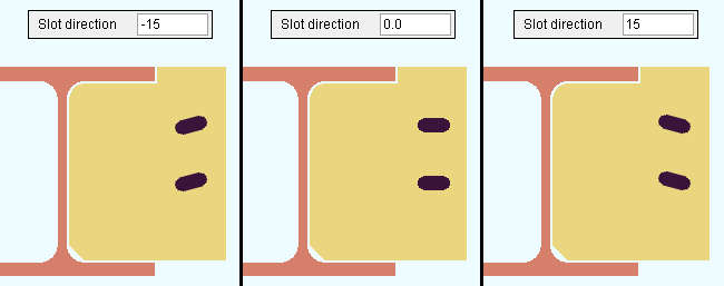
' 0 ' (zero) degrees orients the length of the slot perpendicular to the beam's web. That is, the slot length will be horizontal if the beam web is vertical.
A ' positive number ' of degrees rotates the slot counterclockwise from its ' 0 ' orientation.
A ' negative number ' of degrees rotates the slot clockwise from its ' 0 ' orientation. .
Rows: The number (a count) of the rows of holes in the outrigger. The holes in a row run horizontally (assuming the beam's web is vertical). Hole rows are numbered vertically (from top to bottom). The top hole is the " Vertical to 1st hole from top of outrigger ." An entry of ' 0 ' stops holes from being generated. An entry of ' 1 ' results in only a single row of holes.
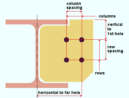
Row spacing: The distance (in the primary dimension " Units " or other units ) between two adjacent holes in the same column of holes.
Vertical to 1st hole from top of outrigger: The distance (in the primary dimension " Units " or other units ) from the top of the outrigger to the nearest hole. This distance is measured parallel with the web of the beam as it is shown in profile. Consequently, this distance is measured vertically if the beam's web is vertical.
Columns: The number (a count) of the columns of holes in the outrigger. The holes in a column run vertically (assuming the beam's web is vertical). Hole rows are numbered horizontally (from outer to inner, right to left in the example below). The hole that is farthest to the outside is the " Horizontal to farthest hole from centerline ." An entry of ' 0 ' stops holes from being generated. An entry of ' 1 ' results in only a single column of holes.
Column spacing: The distance (in the primary dimension " Units " or other units ) between two adjacent holes in the same row of holes.
Horizontal to farthest hole from centerline: The distance (in the primary dimension " Units " or other units ) from the centerline of the beam to the farthest column of holes. This distance is measured perpendicular to the beam's centerline, horizontally if the beam's web is vertical. In the illustration below, this dimension is labeled "horizontal to far hole."
Bolt information
Bolt diameter: You can enter a bolt diameter in the primary dimension " Units " or other units . The diameter you enter will become the " Bolt diameter " on the Hole Edit window for each of the outrigger pin holes.
| diameter |
|
Outrigger does not automatically add bolts. If you Match Holes to a material that faces this outrigger and choose to add bolts through those holes, the newly added bolts will, by default, be the " Bolt diameter " specified here.
Bolt type: A490N or A490SC or A307 , etc. This will be the " Preferred bolt type " on the Hole Edit window for each of the outrigger pin holes. Select from the list box ( ![]() ) the type of bolt to be used. Bolt types listed on the menu come from the Bolt Specifications .
) the type of bolt to be used. Bolt types listed on the menu come from the Bolt Specifications .
Outrigger does not automatically add bolts. If you Match Holes to a material that faces this outrigger and choose to add bolts through those holes, the newly added bolts will, by default, be the " Bolt type " specified here.
![]() Weld Information ---------------------------------------------------------------------------
Weld Information ---------------------------------------------------------------------------
' Yes ' instructs Outrigger to shop weld the outriggers to the beam.
' No ' instructs the Outrigger custom component to not add welds.
Weld type: Fillet or Square groove or Bevel groove . This sets the " Weld type " on the Weld Edit window in Modeling as well as the " Weld type " for the weld symbol on the beam detail.
| symbol | name | weld used for... |
|
|
fillet | General welding of material. |
|
|
square groove | Butt joints. |
|
|
bevel groove | General full penetration welding of material. |
Weld size: A distance (in the primary dimension " Units " or other units ) that indicates depth of preparation, size or strength of the weld. This sets the " Weld size " on the Weld Edit window in Modeling as well as the " Weld size " for the weld symbol on the beam detail.
Tail text: blank or a text string . This sets the " Supplementary tail text " on the Weld Edit window in Modeling as well as the " Supplementary tail text " for the weld symbol on the beam detail.
|
This weld symbol's tail text is TYP . |
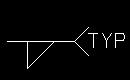
If this field is left ' blank ', a tail is not drawn on the weld symbol.
If a ' text string ' is entered, a tail with that character string as the tail text is drawn on the weld symbol.

