DSTV Options
- General Overview
- Tips and Tricks
- Related Tools
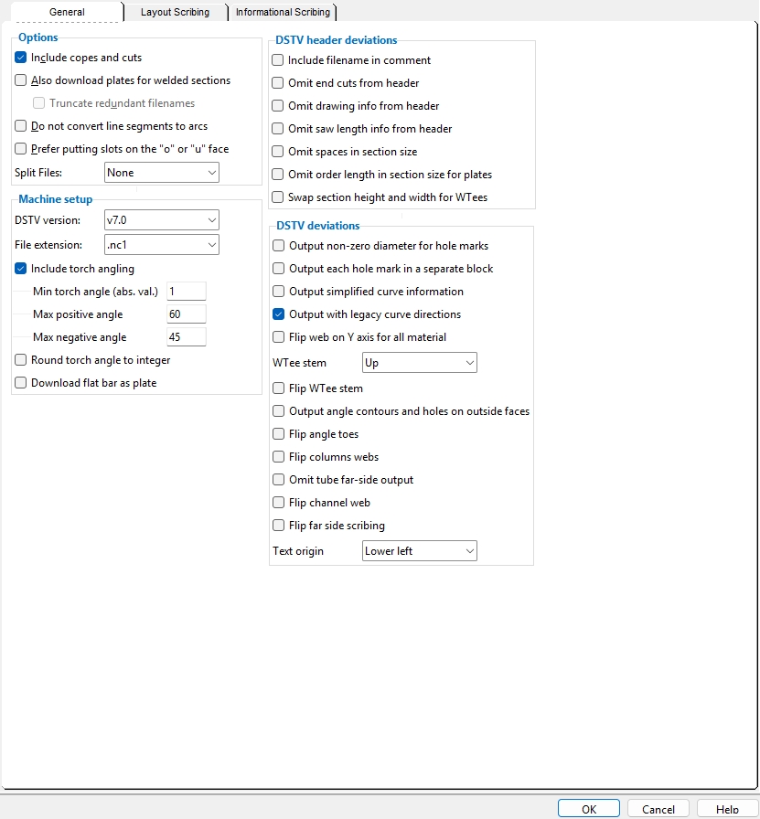
General
Options
If this box
is checked, the DSTV download file will include instructions for the placement of copes and cuts along with instructions on the placement of holes.
If this box
is not checked, the DSTV download file will only include instructions for the placement of holes. The download file will not include copes and cuts.
Also download plates for welded sections: ![]() or
or ![]() . This applies when you download a welded plate wide flange or a welded plate box member. Case 2 also applies if you download a welded plate wide flange or a welded plate box submaterial.
. This applies when you download a welded plate wide flange or a welded plate box member. Case 2 also applies if you download a welded plate wide flange or a welded plate box submaterial.
Case 1 :
Case 2 :
Case 3 :
If this box
If this box
Case 1 : For a beam or a column or vertical brace on which
Case 2 : For a beam or a column or vertical brace on which
Truncate redundant file names: ![]() or
or ![]() . This applies when Download plates (too) is checked and you download a welded plate wide flange or a welded plate box member and
. This applies when Download plates (too) is checked and you download a welded plate wide flange or a welded plate box member and ![]() Welded section is single material is not checked for a beam or a column or vertical brace and the piecemarking setup option
Welded section is single material is not checked for a beam or a column or vertical brace and the piecemarking setup option ![]() Use member mark for member main material in model is checked.
Use member mark for member main material in model is checked.
|
|
If this box
If this box
Do not convert line segments to arcs: ![]() or
or ![]() .
.
If this box
If this box
Prefer putting slots on the o or u face: ![]() or
or ![]() . This applies to downloads of angles with slots. In the DSTV standard, the o and u faces are on the leg of the angle that is vertical on the CNC machine.
. This applies to downloads of angles with slots. In the DSTV standard, the o and u faces are on the leg of the angle that is vertical on the CNC machine.
 The o and u faces of an angle.
If this box
If this box
Split Files: None or Scribing or Sequence or Both.
None keeps all instances of the same material included in the same.nc1 download file. The file will not include scribing instructions.
Scribing applies to members or materials that are downloaded with the option to scribe Placement marks for.It applies when different placement or piecemark scribing is required for different instances of a material or member with the same piecemark. The SDS2 CNC program will generate a separate file for each scribing need. The files might be named, for example, p3-0.nc1 , p3-1.nc1 , p3-2.nc1 , etc.
Sequence causes downloads of submaterials which run across different sequences to be output in separate files. The files might be named, for example, a45-0.nc1 , a45-1.nc1 , etc., and each file will report the quantity of only those instances of the material that are in the particular sequence.
Both splits the CNC download files by both scribing and sequence.
Note: The option to split files by scribing is mainly for submaterials. However, similar scribing conflicts may occur when you download a member main material by
Submaterial. The way to get around this problem for member main material is to, instead, download by
Machine Setup
Select v5.0 to output a download file using DSTV-nc1 version 5 standard.
Select v7.0 to output a download file using DSTV-nc1 version 7 standard.
File extension: .nc1 or .nc or .dat.
.nc1 adds an.nc1 extension (e.g., B_1.nc1 ) to subsequently generated DSTV download files.
.nc adds an.nc extension (e.g., B_1.nc ) to subsequently generated DSTV download files.
.dat adds a.dat extension (e.g., B_1.dat ) to subsequently generated DSTV download files.
Naming of DSTV files: DSTV files are named after either a member piecemark (upper case) or a submaterial piecemark (lower case), depending on how the members or materials are selected. The File extension that is selected here is then added to that name.
|
|||
|
If this box
If this box
Minimum torch angle (abs. value): A positive number of degrees from 0 to 90.
| Examples of Torch Angles (These are all positive angles -- interior to exterior. The minimum set here also applies to negative angles.) |
||||||
|
Effect on the download: Torch angles that are less than the Minimum torch angle will not be downloaded. 0 is vertical and permits any torch angle to be downloaded. An entry of 10 causes only those torch angles that are 10 degrees or more from vertical (clockwise or counterclockwise) to be included in the download file.
A possible application: Suppose that your CNC machine can only handle a single cut on the same edge. This is a problem because the sloping beam with a welded moment connection that you want to download to this machine has two bevel cuts on the same end -- one from the web cut, the other from the field weld preparation. Properly setting a Minimum torch angle is a way for you to get only one cut in the download file.
Max positive angle: The maximum positive angle that you want to allow in the DSTV download file. If the angle of a web cut or field weld prep or etc. exceeds the angle you enter here, that cut will not be included in the download file. Be aware that an angle that is positive in SDS2 may be negative in the DSTV file. See the example below.
| This example shows what, in the 3D model, is a single Web cut of 45 degrees . In the DSTV download file, this web cut is two cuts, one positive, the other negative. |
|
Max negative angle: Same as Max positive angle ,except that this applies to negative torch angles in the DSTV file.
| In the 3D model, this is one Web cut of 45 degrees . DSTV sees it as two cuts, one positive, one negative. If your Max positive angle was 60 and your Max negative angle was 30, only the positive cut would be included in the download file. |
|
Round torch angle to integer: ![]() or
or ![]() . This applies when you choose to
. This applies when you choose to ![]() Include torch angle in the download file.
Include torch angle in the download file.
|
|||
|
If this box
If this box
Download flat bar as plate: ![]() or
or ![]() . The following example shows the part of a DSTV file that is affected by this option.
. The following example shows the part of a DSTV file that is affected by this option.
|
|
If this box
If this box
Note: This option does not apply to a flat bar that was created from a rectangular plate by substituting the description from the Preferred Flat Bar Sizes list. For such a material, DSTV always uses the description prefix for plates, regardless of the choice made here.
DSTV header deviations
Include filename in comment: ![]() or
or ![]() .
.
|
|
If this box
If this box
Omit end cuts from header: ![]() or
or ![]() . This applies when the member or material has a Web cut.The DSTV download file's header has two lines ( 18 and 19 in the examples below) for designating web cuts. The first of these lines is for a web cut on the left end, the second is for the right end.
. This applies when the member or material has a Web cut.The DSTV download file's header has two lines ( 18 and 19 in the examples below) for designating web cuts. The first of these lines is for a web cut on the left end, the second is for the right end.
|
|
If this box
If this box
Omit drawing info from header: ![]() or
or ![]() . This option was added for compatibility with Steel Projects software, but may also apply to other situations.
. This option was added for compatibility with Steel Projects software, but may also apply to other situations.
|
|
If this box
If this box
Omit saw length info from header: ![]() or
or ![]() . This option was added to accommodate older Ficep machines, but may also be applied to downloads for other machines. It applies when Dimension from saw length is not checked (
. This option was added to accommodate older Ficep machines, but may also be applied to downloads for other machines. It applies when Dimension from saw length is not checked ( ![]() ), but the piece would be longer if that option were checked.
), but the piece would be longer if that option were checked.
|
||||||
|
The saw length in this example is 5-0 , which is 1524 mm
(5 x 12 x 25.4). |
If this box
If this box
Note: When Dimension from saw length is
Omit spaces in section size: ![]() or
or ![]() . This option was added for compatibility with WinCad software, which may have problems reading the section size in older machines when there is a space in the section size. Other machines and software may also have this problem. Spaces are conventionally used in the names of imperial section sizes such as the L6x3 1/2x1/2 section in the example below.
. This option was added for compatibility with WinCad software, which may have problems reading the section size in older machines when there is a space in the section size. Other machines and software may also have this problem. Spaces are conventionally used in the names of imperial section sizes such as the L6x3 1/2x1/2 section in the example below.
|
|
If this box
If this box
Omit order length in section size for plates: ![]() or
or ![]() .
.
|
|
If this box
If this box
Swap section height and width for W tees: ![]() or
or ![]() .
.
 |
 |
If this box
If this box
DSTV deviations
Output non-zero diameter for hole marks: ![]() or
or ![]() .
.
 |
 |
If this box
If this box
Output each hole mark in a separate block: ![]() or
or ![]() .
.
 |
|
If this box
If this box
Output simplified curve information: ![]() or
or ![]() .
.
|
Curve information is used to describe any radiused or curved cut, including cope radii (as shown), cut layouts made with Corner Rounding turned on, and Exact Fits to a radiused material such as a pipe. |
If this box
If this box
Output with legacy curve directions : ![]() or
or ![]() . This option configures the download file so that the contour of a rolled section ( wide flange , tube , etc.) correctly depicts the radius of the cut.
. This option configures the download file so that the contour of a rolled section ( wide flange , tube , etc.) correctly depicts the radius of the cut.
|
A top flange contour with cut radii that are convex instead of concave. |

|
The same top flange, as it is supposed to look in your software. |
Leave the
Flip web on Y axis for all material: ![]() or
or ![]() . This option was added for use with Peddimat software and for Ficep machines. It applies to all material types.
. This option was added for use with Peddimat software and for Ficep machines. It applies to all material types.
|
A wide flange web that is flipped vertically. Note that the top and bottom flanges are not flipped. |
|
The same wide flange web, as it is supposed to look in your software. |
Leave the
WTee stem: Up or Down or Right or Left.
' Up

|
' Down

|
' Right

|
' Left

|
Up orients the W tee stem up in the DSTV download file. Down orients the W tee stem down. Right orients the W tee stem toward the right. Left orients the W tee stem toward the left.
Flip WTee stem: ![]() or
or ![]() . This option lets you configure the download file so that W tee stems are shown correctly in the viewer you use to view that file.
. This option lets you configure the download file so that W tee stems are shown correctly in the viewer you use to view that file.
|
A W tee whose stem is flipped vertically , so that it appears upside-down. The flange is not flipped -- only the stem is flipped. |
|
The same W tee , as it is supposed to look in your software. |
Leave the
Output angle contours and holes on outside faces: ![]() or
or ![]() . This option was added for PythonX users.
. This option was added for PythonX users.
If this box
If this box
Flip angle toes: ![]() or
or ![]() . This option lets you configure the download file to compensate for differences in how angles are represented in different DSTV viewers.
. This option lets you configure the download file to compensate for differences in how angles are represented in different DSTV viewers.
 |
 |
If this box
If this box
Flip column webs: ![]() or
or ![]() . This lets you configure the download file so that the contour of a wide flange or tube (HSS rectangular) column web is correctly depicted in the DSTV viewer you use to look at that file. This option was added for users of VersaFab on Python X machines, but may also apply to other situations.
. This lets you configure the download file so that the contour of a wide flange or tube (HSS rectangular) column web is correctly depicted in the DSTV viewer you use to look at that file. This option was added for users of VersaFab on Python X machines, but may also apply to other situations.
|
A column web that is flipped vertically. Note that the top and bottom flanges are not flipped. |
|
The same column web, as it is supposed to look in your software. |
Leave the
Omit tube far-side output: ![]() or
or ![]() . This may apply when you download tube sections to older Ficep machines. It is required for older Ficep machines running Arianna.
. This may apply when you download tube sections to older Ficep machines. It is required for older Ficep machines running Arianna.
If this box
If this box
Flip channel web: ![]() or
or ![]() . This option lets you configure the download file so that channel web holes and cuts are shown correctly in the DSTV viewer you use to look at that file.
. This option lets you configure the download file so that channel web holes and cuts are shown correctly in the DSTV viewer you use to look at that file.
|
|
A channel web that is flipped vertically. Note that the top and bottom flanges are not flipped. |
|
|
The same channel web, as it is supposed to look in your software. |
Leave the
Flip far side scribing: ![]() or
or ![]() . This option lets you configure the download file so that far-side scribing is shown correctly in the DSTV viewer you use to view that file.
. This option lets you configure the download file so that far-side scribing is shown correctly in the DSTV viewer you use to view that file.
|
Far-side scribing that is flipped vertically. |
|
The same scribing, as it is supposed to look in the DSTV viewer. |
Leave the
A special case: For plates, this applies to more than just far side scribing. It flips the scribing on the other side when Send out plates is Near side or Far side. In other words, when Send out plates is Near side, it flips the scribing on the far side; when Send out plates is Far side, it flips the scribing on the near side.
Text origin: Lower left or Left center. The DSTV standard does not specify the origin for an SI text block. Consequently, manufacturing practices vary. Which choice gives you the best result depends on the manufacturer of the CNC machine that you use.

Lower left is the default origin for scribed test. If using this default causes scribed text to be placed lower than you want it to be, then switch to using Left center as the Text origin.
Left center should be your choice if Lower left results in scribed text being placed lower than you want it to be.
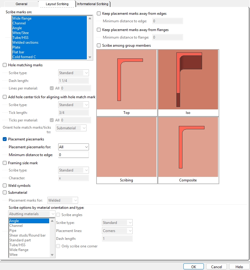
Layout Scribing
Scribe marks on: Wide flange and/or Channel and/or Angle and/or W tee / S tee and/or Tube / HSS and/or Welded sections and/or Plate and/or Flat bar and/or Cold formed C. No matter which choices are made here, scribing around the scribed-to material's k-distance is omitted.
Select the materials that you want to be scribed on.
The options Hole matching marks and/or Placement piecemarks and/or Scribe among group members and/or Framing side mark and/or Weld symbols and/or Submaterial will apply scribing to only those material types that you have selected here.
For the most part, scribing is done on member main materials or gusset plates. You can Download member main materials by Details or Detail sheets or, in Modeling , you can Download Members by Location or select member main materials when you Download Material by Location.
Hole matching marks: ![]() or
or ![]() . This applies to member main material that has submaterial shop welded to it. A shear plate or end plate or clip angle or gusset plate may shop weld to a member.
. This applies to member main material that has submaterial shop welded to it. A shear plate or end plate or clip angle or gusset plate may shop weld to a member.
|
||
| A shear plate welded to the web of a column. The Lines per hole group is set to All. The scribing of Submaterial is turned on so that the shear plate is scribed, but you would still get the matching marks (in the left example) even if the shear plate was not scribed. |
If this box
If this box
Scribe type: Standard or Powdering. This applies when the box is checked for
Standard or Powdering are identical with respect to the result that you get when you choose to scribe Hole matching marks. Standard is the scribe type used by most CNC machines.
Dash length: The length of the Hole matching marks.
Lines per material:
1
2
3 or all
1 scribes one Hole matching mark.The line is drawn through the hole that is nearest the left end of the member main material when Orient match marks/ticks to is set to Main material.
2 scribes two Hole matching marks.One line is through the center of the hole that is nearest the left end of the member main material. The other line is through hole that is farthest from the left end.
3 or 4 or ... scribes Hole matching marks through potentially as many holes as the number specified. If the number specified is greater than or equal to the number of holes in the material, the results will be the same as if you had checked the box for
Add hole center tick for aligning with hole match mark: ![]() or
or ![]() . This applies to materials that shop weld to a member main material.
. This applies to materials that shop weld to a member main material.
|
||
| A shear plate. The Ticks per material is set to All. |
If this box
If the box
Scribe type: Standard or Powdering. This applies when the box is checked for
Standard or Powdering are identical with respect to the result that you get when you choose to Add hole center tick....Standard is the scribe type used by most CNC machines.
Tick length: The length of the tick marks that are scribed for
Ticks per material:
1
2
3 or all
2 or all Shear plates are shown above.
An end plate is shown at left. For an end plate, each number of Ticks per material results in a pair of ticks being scribed. An end plate shop welds to the web of the supported beam, and the ticks are placed accordingly.
1 scribes one tick for the hole that is nearest to the left end of the member main material when Orient hole match marks/ticks to is set to Main materia l.
2 scribes two ticks, one for each of the outside holes.
3 or 4 or ... scribe s the number of ticks that are specified. If the number specified is greater than or equal to the number of holes in the material, the results will be the same as if you had checked the box for
Orient hole match marks/ticks to: Submaterial or Main material. This applies when the box is checked for either or both ![]() Hole matching marks.and/or
Hole matching marks.and/or ![]() Add hole center tick for aligning with hole match mark.The results are the same for either choice if an even number of matching marks or ticks have been designated. You may get different results, depending on the choice made here, when an odd number of marks or ticks have been designated.
Add hole center tick for aligning with hole match mark.The results are the same for either choice if an even number of matching marks or ticks have been designated. You may get different results, depending on the choice made here, when an odd number of marks or ticks have been designated.
Submaterial orients a single match mark and/or tick so that it is closest to a material reference point. Since that reference point is the same for all submaterials with the same piecemark, this can prevent the DSTV submaterial download file from being split into separate files due to scribing.
Main material orients a single match mark and/or tick so that it is closest to the left end of the member main material. This choice may be desirable if you are not using tick marks.
 |
 |
If this box
If this box
Placement piecemarks for: Welded or all.
' Welded restricts placement piecemarks to being scribed only for materials that weld to a member in the shop.
' All permits placement piecemarks to be scribed for all submaterials, regardless of whether they shop weld or shop bolt to a member in the shop.
Minimum distance to edge: The distance that the placement piecemark will be placed from the edge of the scribed material.
Framing side mark: ![]() or
or ![]() . A framing side mark is used for erection purposes to show on which side of a shear plate to frame the supported beam or vertical brace gusset plate that bolts to that shear plate.
. A framing side mark is used for erection purposes to show on which side of a shear plate to frame the supported beam or vertical brace gusset plate that bolts to that shear plate.
|
A framing side mark is 1 x 1 inch (25.4 x 25.4 mm). It is scribed to show the framing side of a shear plate. |
|
A framing side mark and a shear plate (Outline) and a Weld symbol. |
If this box
If this box
Tip: You get a similar framing side symbol on member details if the box is checked for Home > Project Settings > Fabricator > Detailing Symbol Settings >
Scribe type: Standard or Powdering or Hole marks or Text.
Standard or Powdering allow the scribing of a Framing side mark that is like the one pictured above. Standard is the scribe type used by most CNC machines.
Hole marks does not allow true scribing, but instead applies a single CNC mark to identify the framing side of the shear plate.
Text results in the framing mark being stenciled using the Character that you specify below.
Character: This option is enabled when the framing side mark Scribe type is Text. Type in a character that is supported in the stencil alphabet that is used by the CNC machine that will be reading the CNC file. The character will be stamped as the Framing side mark on the side of the shear plate that the supported beam frames to. If you type in a character that is not in the CNC machine's stencil alphabet, the machine may substitute a different character or may not give you a character at all. The default entry to the framing side Character is an X.
Weld symbols: ![]() or
or ![]() . The weld must exist in Modeling for you to get its symbol.
. The weld must exist in Modeling for you to get its symbol.
|
A weld symbol and a shear plate (Outline) and a Framing side mark. |
If this box
If this box
If this box
If this box
Note: If Scribe standard parts as is set to Submaterial, then standard parts are scribed using the Scribe type and Placement lines for submaterial, regardless of whether this option (Submaterial) is checked or not. Similarly, if Scribe among Grouped members is checked, submaterial settings are used.
Placement marks for: Welded or All. This applies not just to member main materials, but also to plates that connection materials can be welded or bolted to. For example, it applies to vertical brace gussets that shear plates or clip angles may be attached to.
Welded formats the download file to include instructions for scribing those submaterials that are shop welded to a member main material or to a plate. This includes user-added as well as system-generated welded material. Only welded submaterial will be included -- bolted submaterial is excluded.
All formats the download file to include instructions for scribing all of a member's submaterials, including those that are shop bolted and shop welded to the member main material.
Keep placement marks away from edges: ![]() or
or ![]() .
.
If this box
If this box
Minimum distance to edge: The distance the placement marks are set from the material edge when Keep placement marks away from edges
Keep placement marks away from flanges: ![]() or
or ![]() .
.
If this box
If this box
Minimum distance to edge: The distance the placement marks are set from the material edge when Keep placement marks away from flanges
Scribe among group members:
![]() or
or ![]() .
.
If this box
If this box
Abutting materials or Flush materials:
If ' Abutting materials is selected, you can select angle or channel or pipe or shear stud/ round bar or standard part or tube/HSS or wide flange or W tee to get settings that apply to scribing layouts tor the selected type of material.
If ' Flush materials is selected , you can select Angle or others or plate to get settings that apply to scribing layouts for the selected type of material.
Note: If Scribe among Grouped members is checked, these settings are used to set the Scribe type ,etc. for scribing submember layouts.
Change Options: Scribe/Do Not scribe submaterial in CNC (turn on/off scribing for selected materials).
General Information: Scribe this material onto others (to track if scribing is on/off).- abutting angle - abutting angle - abutting angle - abutting angle -
Scribe angles :
For this example, Scribe type is Standard and Placement lines is Outline. If the boxes for Scribe angles and Submaterial
If the box for Scribe angles
Scribe type: Standard or Powdering or Hole marks. This applies when
' Standard
' Powdering
Hole Marks Standard and Powdering are identical with respect to how they affect angle scribing settings such as the Placement lines ,etc. Standard is the scribe type used by most CNC machines.
Hole marks does not allow true scribing, but instead places a mark at each corner when the Placement lines is set to Outline. If Placement lines is set to Corner, three marks are placed at each corner. Set this to Hole marks, for example, if the CNC machine you are downloading to does not support true scribing.
Placement lines: Outline or Corners. This applies when
' Outline
' Corners
For both of these examples , the Scribe type is either Standard or Powdering. Outline generates instructions in the download file for scribing a complete outline of each abutting angle wherever that abutting angle overlaps the downloaded material.
Corners works like Outline, except that only the corners of each abutting angle that overlaps the downloaded material are scribed. For the Corners example shown above, Only scribe one corner is not checked.
Dash length: The length when the Placement lines is Corners. Each segment at the corner will be the Dash length.

Only scribe one corner:
For both examples , Placement lines is Corners and Scribe type is either Standard or Powdering. If this box
If this box
- flush angle - flush angle - flush angle - flush angle -
Scribe angles :
For this example, Scribe type is Standard and Placement lines is Outline. If the boxes for Scribe angles and Submaterial
If the box for Scribe angles
Scribe type: Standard or Powdering or Hole marks. This applies when Angle is selected for Flush materials and
' Standard
' Powdering
Hole Marks Standard and Powdering are identical with respect to how they affect angle scribing settings such as the Placement lines ,etc. Standard is the scribe type used by most CNC machines.
Hole marks does not allow true scribing, but instead places a mark at each corner when the Placement lines is set to Outline. If Placement lines is set to Corner, three marks are placed at each corner. Set this to Hole marks, for example, if the CNC machine you are downloading to does not support true scribing.
Placement lines: Outline or Corners or Dashed. This applies when Angle is selected for Flush materials and
Outline ' Corners
' Dashed
For all three examples, Placement piecemarks is checked. Outline generates instructions in the download file for scribing a complete outline of the angle wherever that angle is flush to the downloaded material.
Corners works exactly like Outline, except that only the corners of the flush angle are scribed.
Dashed works like Corners, except that additional dashes are placed between the corners using the Dash length and Gap at least specified below.
Dash length: The length when the Placement lines is Dashed or Corners.
For a Dashed placement line , each dash will be the Dash length ,and the spaces between dashes will be, at least, the Gap at least specified below.
For a Corners placement line , each segment at the corner will be the Dash length.
Gap at least: The minimum distance between dash segments when Placement lines is Dashed.

Draw line indicating opposite side leg:
For this example, Scribe type is Standard and Placement lines is Outline. If this box
If this box
- flush other - flush other - flush other - flush other - flush other -
Scribe other flush materials:
For this example, Scribe type is Standard and Placement lines is Outline. The material could be a wide flange or W tee or channel. If the boxes for Scribe other flush materials and Submaterial
If the box for Scribe other flush materials
Scribe type: Standard or Powdering or Hole Marks. This applies when
' Standard
' Powdering
Hole Marks Standard and Powdering are identical with respect to how they affect other settings for flush material scribing (e.g., Placement lines). Standard is the scribe type used by most CNC machines.
Hole marks does not allow true scribing, but instead places a mark at each corner when the Placement lines is set to Outline. If Placement lines is set to Corner, three marks are placed at each corner (
=
). Set this to Hole marks, for example, if the CNC machine you are downloading to does not support true scribing.
Placement lines: Outline or Corners or Dashed. This applies when Other is selected for Flush materials and the boxes for
Outline ' Corners
' Dashed
Outline generates instructions in the download file for scribing a complete outline of the other material (W, C, WT, HSS) wherever that material is flush to the downloaded material.
Corners works exactly like Outline, except that only the corners of the flush material (W, C, WT, HSS) are scribed.
Dashed works like Corners, except that additional dashes are placed between the corners using the Dash length and Gap at least specified below.
Dash length : The length of the dash when Placement lines is set to Dashed or Corners.
For a Dashed placement line , each dash will be the Dash length ,and the spaces between dashes will be, at least, the Gap specified below.
For a Corners placement line , each segment at the corner will be the Dash length.
Gap at least : The minimum distance (in the primary dimension Units or other units ) when Placement lines is set to Dashed.
- plates - plates - plates - plates -
Scribe plates:
For this example, Scribe type is Standard and Placement lines is Outline. If the boxes for Scribe plates and Submaterial
If the box for Scribe plates
Scribe type: Standard or Powdering or Hole Marks. This applies when Plates is selected for Flush materials and the boxes for
' Standard
' Powdering
Hole Marks Standard and Powdering are identical with respect to how they affect plate scribing settings such as the Placement lines ,etc. Standard is the scribe type used by most CNC machines.
Hole marks does not allow true scribing, but instead places a mark at each corner when the Placement lines is set to Outline. If Placement lines is set to Corner, three marks are placed at each corner. Set this to Hole marks, for example, if the CNC machine you are downloading to does not support true scribing.
Placement lines: Outline or Corners or Dashed. This applies when Plates is selected for Flush materials and the boxes for
Outline ' Corners
' Dashed
Outline generates instructions in the download file for scribing a complete outline of a plate material that is flush to the downloaded material.
Corners works exactly like Outline, except that only the corners of the flush material (W, C, WT, HSS) are scribed.
Dashed works like Corners, except that additional dashes are placed between the corners using the Dash length and Gap at least specified below.
Dash length : The length of the dash when Placement lines is set to Dashed or Corners.
For a Dashed placement line, each dash will be the Dash length ,and the spaces between dashes will be, at least, the Gap specified below.
For a Corners placement line, each segment at the corner will be the Dash length.
Gap at least : The minimum distance between dashes when Placement lines is set to Dashed.
- channel - channel - channel - channel -
Scribe channels :
For this example , Scribe type is Standard and Placement lines is Outline. If the boxes for Scribe channels and Submaterial are both checked (
If the box for Scribe channels is not checked (
Scribe type: Standard or Powdering or Hole Marks. This applies when
' Standard
' Powdering
Hole Marks Standard and Powdering are identical with respect to how they affect channel scribing options such as the Placement lines, etc. Standard is the scribe type used by most CNC machines.
Hole marks does not allow true scribing, but instead places a mark at each corner when the Placement lines is set to Outline. If Placement lines is set to Corner, three marks are placed at each corner. Set this to Hole marks, for example, if the CNC machine you are downloading to does not support true scribing.
Placement lines: Outline or Corners. This applies when
' Outline
' Corners
For both of these examples, the Scribe type is either Standard or Powdering. Outline generates instructions in the download file for scribing a complete outline of each abutting channel wherever that abutting channel overlaps the downloaded material.
Corners works like Outline, except that only the corners of each channel that overlaps the downloaded material are scribed. For theCorners' example shown above, the Multiplier for line along web is 2 and the Scribe corner count is 2.
Dash length: The length when the Placement lines is Corners. Each segment at the corner will be the Dash length so long as the Multiplier for line along web is set to 1.
Scribe corner count: 1 or 2. This applies when the Placement lines is Corners.
' 1
' 2
For both examples, the Multiplier for line along web is 2 and the Scribe corner count is 2. Multiplier for line along web: The factor (a decimal number) by which you want to multiply the Dash length when Placement Lines is Corners and the line segment of a corner is parallel with the web of the channel.
1
2
3
- pipe - pipe - pipe - pipe - pipe -
Scribe pipes :
If the boxes for Scribe pipes and Submaterial
If the box for Scribe pipes
Scribe type: Standard or Powdering. This applies when
' Standard
' Powdering
Standard and Powdering are identical with respect to how they affect scribing options such as the Placement lines ,etc. Standard is the scribe type used by most CNC machines.
- shear stud and round bar - shear stud and round bar -
Scribe round bars and shear studs :
In this example, the Scribe shape is X. If the boxes for Scribe round bars and shear studs and Submaterial
If the box for Scribe round bars and shear studs
Note: If Scribe standard parts as is set to Shear studs, then standard parts are scribed using the Scribe type for shear studs regardless of whether this option is checked or not.
Scribe type: Standard or Powdering or Hole marks. This applies when Placement marks for is set to All or Welded and when
Standard or Powdering results in the shear stud being scribed in an L (or X) shape, which represents the stud diameter per the choice made to Scribe diameter of.
Hole marks does not allow true scribing, but instead places a CNC mark at the center of the shear stud (L or X = *). You might set this to Hole marks, for example, if the CNC machine you are downloading to does not support true scribing.
Scribe diameter of: Rod or Head. Scribing of shear studs may be done when Placement marks for is set to All or Welded. This applies when the Scribe type is Standard or Powdering. Round bars do not have heads, which means that round bar scribing will effectively ignore the choice made here.
Rod Head 
Rod makes each line segment of the L a length that is equal to the Stud diameter.When the Scribe shape is X , the distance is also the length of either of the two line segments.
Head makes the two line segments of the L or X of a shear stud to each be a length that is equal to the shear stud's Head diameter.
Scribe shape: L or X. This applies when the Scribe type is Standard or Powdering.


L scribes the shear stud or round bar with an L shape
X scribes the shear stud or round bar with an X shape.
- standard parts - standard parts - standard parts -
Scribe standard parts :
If the boxes for Scribe standard parts and Submaterial
If the box for Scribe standard parts
Use the same options as: Plates or Shear studs. A standard part can be created in Modeling using Fuse Material. DSTV is able to scribe a standard part onto the surface of a material if the standard part is sufficiently close (within 1/16 inch) of the surface.
Plates causes the the standard part to be scribed as an outline using the Scribe type and Placement lines ,etc. that are used for plates. You might want to do this, for example, if the standard part is flush to the downloaded material.
Shear studs causes the standard part to be scribed in the same way that shear studs are scribed, using the scribing settings for shear stud Scribe type and shear stud Scribe shape ,etc. You might want to do this, for example, if the standard part abuts to the downloaded material like a shear stud.
- tube/HSS - tube/HSS - tube/HSS - tube/HSS -
Scribe HSS and tubes :
If the boxes for Scribe HSS and tubes and Submaterial
If the box for Scribe HSS and tubes
Scribe type: Standard or Powdering or Hole marks. This applies when
' Standard
' Powdering
Hole Mark Standard and Powdering are identical with respect to how they affect scribing options such as the Placement lines ,etc. Standard is the scribe type used by most CNC machines.
Hole marks does not allow true scribing, but instead places a mark at each corner when the Placement lines is set to Outline. If Placement lines is set to Corner, three marks are placed at each corner. Set this to Hole marks, for example, if the CNC machine you are downloading to does not support true scribing.
Placement lines: Outline or Corners. This applies when
' Outline
' Corners
Outline generates instructions in the download file for scribing a complete outline of each abutting HSS or tube wherever that material overlaps the downloaded material.
Corners works like Outline, except that only the corners of each HSS or tube that overlaps the downloaded material are scribed.
Dash length: The length when the Placement lines for the tube/HSS section is Corners. Each segment at the corner will be the Dash length.
- wide flange - wide flange - wide flange - wide flange -
Scribe wide flange :
If the boxes for Scribe wide flange and Submaterial
If the box for Scribe wide flange
Scribe type: Standard or Powdering or Hole marks. This applies when
' Standard
' Powdering
Hole Marks Standard and Powdering are identical with respect to how they affect scribing options such as the Placement lines ,etc. Standard is the scribe type used by most CNC machines.
Hole marks does not allow true scribing, but instead places a mark at each corner when the Placement lines is set to Outline. If Placement lines is set to Corner, three marks are placed at each corner. Set this to Hole marks, for example, if the CNC machine you are downloading to does not support true scribing.

Placement lines: Outline or Corners. This applies when ![]() Submaterial and
Submaterial and ![]() Scribe wide flange are checked.
Scribe wide flange are checked.
' Outline
' Corners
Outline generates instructions in the download file for scribing a complete outline of each abutting wide flange wherever that material overlaps the downloaded material.
Corners works like Outline, except that only the corners of each abutting wide flange that overlaps the downloaded material are scribed. For the Corners example shown above, the Multiplier for line along flange is set to 2.
Dash length: The length when the Placement lines for the wide flange section is Corners. Each segment at the corner will be the Dash length so long as the Multiplier for line along flange is 1.
Include corners: Top flange left and/or Top flange right and/or Bottom flange left and/or Bottom flange right. This applies when Placement lines is set to Corners.
|
Outlines are shown in this illustration for reference, to help you more easily identify which corner is which. This option only affects the download file when Placement lines is set to Corners. |
If the box for a corner
If the box for a corner
Multiplier for line along flange: The factor (a decimal number) by which you want to multiply the Dash length when Placement lines is Corners and the line segment of a corner is parallel with the flanges of the wide flange.
- W tee - W tee - W tee - W tee - W tee -
Scribe Wtees :
If the boxes for Scribe Wtee and Submaterial
If the box for Scribe W tee
Scribe type: Standard or Powdering or Hole marks. This applies when
' Standard
' Powdering
Hole Marks Standard and Powdering are identical with respect to how they affect scribing options such as the Placement lines ,etc. Standard is the scribe type used by most CNC machines.
Hole marks does not allow true scribing, but instead places a mark at each corner when the Placement lines is set to Outline. If Placement lines is set to Corner, three marks are placed at each corner. Set this to Hole marks, for example, if the CNC machine you are downloading to does not support true scribing.
Placement lines: This applies when
' Outline
' Corners
Outline generates instructions in the download file for scribing a complete outline of each abutting W tee wherever that material overlaps the downloaded material.
Corners works like Outline, except that only the corners of each W tee that overlaps the downloaded material are scribed. For the Corners example shown above, the Multiplier for line along flange is set to 2.
Dash length: The length when the Placement lines for the wide flange section is Corners. Each segment at the corner will be the Dash length so long as the Multiplier for line along flange is 1.
Scribe corner count: 1 or 2. This applies when the Placement lines is Corners.
' 1
' 2
' 1 causes only the left corner of the top flange of the W tee to be scribed, along with the bottom of the stem.
' 2 causes both corners of the top flange of the W tee to be scribed.
Multiplier for line along flange: The factor (a decimal number) by which you want to multiply the Dash length when Placement lines is Corners and the line segment of a corner is parallel with the flange of the W tee.
' 1
|
' 2
|
' 3
|
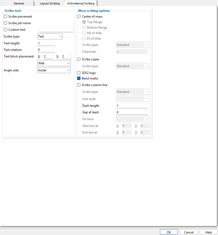
Informational Scribing
Scribe text
 |
 |
If this box
If this box
 |
|
If this box
If this box
If this box
If this box
Scribe type: Text or Powdering or Standard. This sets the block that is used for Scribe piecemark Scribe job name and Custom text.
Text lets the font that is used for stenciling be designated by the CNC machine. Usually the characters are stamped onto the surface.
Powdering or Standard scribe types apply the font that auto detailing uses for details. The characters are scribed onto the surface.
Text height: The height of the characters that will be scribed. This applies to characters that are scribed when Scribe piecemark and/or Scribe job name are checked.
Text rotation: A positive or negative number from 999 to -999 degrees. This applies to characters that are scribed when Scribe piecemark and/or Scribe job name are checked.

|
|
rotation is around the left end of the text. |
An entry of 0 degrees sets the scribed characters to be horizontal. That is, parallel with the X axis (length) of the material.
A positive number of degrees rotates the scribed characters counterclockwise from horizontal around the left end of the text.
A negative (-) number of degrees rotates the scribed characters clockwise from horizontal around the left end of the text.
Text block placement: This sets the X and Y distance for scribing the piecemark and/or Job name on the Web or Top flange or Both web & flange of the material. As shown in the illustration below, if both Scribe piecemark and Scribe job name are checked, the Job name is placed first, followed by a space then the piecemark. Note: This Text block placement setting may be adjusted in the download file to prevent the Job name or piecemark from overlapping a cope or hole.
' Web
|
' Top flange
|
X is the distance from the left end of the material to the left end of the scribed characters. This applies to all material types that are downloadable when DSTV is the CNC configuration type.
Y is the distance from the top flange if Web is selected to the top of the scribed characters. If Top flange is selected, this distance is measured from the far side edge of the top flange to the top of the scribed characters. The Y distance for plates and bars is measured from the top edge of the plate regardless of whether Web or Top flange is selected.
Web places the scribed characters on the near side of the web of the material. For an angle , the reference point is the heel (outside corner) of the angle, and the scribing is placed on the long leg.
Top flange places the scribed characters on the near side of the top flange of the material. This applies to wide flange , S shape , welded plate wide flange , W tee , S tee , channel , tube and angle material. It does not apply to plate or bar materials, which always are scribed on the near side face. For an angle, the scribing is placed on the short leg.
Both puts scribing on both the near side of the web and the top flange.
Angle Side: Inside or Outside.
Inside sets the scribed marks on the inside face of the angle leg.
Outside sets the scribed marks on the outside face of the angle leg.
More scribing options
Center of mass: ![]() or
or ![]() . This applies when you download member main materials. You can Download member main materials by
. This applies when you download member main materials. You can Download member main materials by ![]() Details or by
Details or by ![]() Detail sheet or, in Modeling , you can Download Members by Location or select member main material when you Download Material by Location. The same code that is used for the Center of Mass tool in Modeling is used to calculate the center of mass. The calculation includes the mass of all submaterials that weld or bolt to the member main material, as well as shop bolts.
Detail sheet or, in Modeling , you can Download Members by Location or select member main material when you Download Material by Location. The same code that is used for the Center of Mass tool in Modeling is used to calculate the center of mass. The calculation includes the mass of all submaterials that weld or bolt to the member main material, as well as shop bolts.
|
A center of mass symbol is 2.2 x 2.2 inches (56 x 56 mm). It is scribed on the top flange. |

If this box
If this box
Location: Top flange, Bottom flange, NS of Web, and FS of web. The center of mass symbol is not placed at the actual center of mass, but is projected to the selected member's Top flange, Bottom flange, NS of Web, and/or FS of web from that actual location.
Scribe type: Standard or Powdering or Hole marks or Text.
Standard or Powdering permit the scribing of a Center of mass symbol that is like the one pictured above. Standard is the scribe type used by most CNC machines.
Hole marks does not allow true scribing, but instead places a single CNC mark at the point on the top flange that the center of mass is projected to. Set this to Hole marks, for example, if the CNC machine you are downloading to does not support true scribing.
Text results in the center of mass location being stenciled on the top flange using the Character that you specify below.
Character: This option is enabled when the center of mass Scribe type is Text. Type in a character that is supported in the stencil alphabet that is used by the CNC machine that will be reading the CNC file. The character will be stamped at the Center of mass location on the downloaded piece's top flange. If you type in a character that is not in the CNC machine's stenc
il alphabet, the machine may substitute a different character or may not give you a character at all. The default entry to the center of mass Character is an +.
Scribe copes: ![]() or
or ![]() . This option was added for Ficep machines, but may also apply to downloads for other machines.
. This option was added for Ficep machines, but may also apply to downloads for other machines.
|
|
If this box
If this box
Scribe type: Standard or Powdering.
Standard or Powdering permit copes to be scribed.
SDS2 logo: ![]() or
or ![]() . This applies when the Scribe type for Submaterial is Standard or Powdering.
. This applies when the Scribe type for Submaterial is Standard or Powdering.
CELLPADDING = 0
|
The SDS2 logo is 3 x 6 inches (76 x 152 mm). It is scribed on the beam web. |
If this box
If this box
Bend marks: ![]() or
or ![]() . Bent plates are downloaded flat, with their bends removed. This option lets you add bend marks to designate where the removed bend was. The option applies only if
. Bent plates are downloaded flat, with their bends removed. This option lets you add bend marks to designate where the removed bend was. The option applies only if ![]() Include layout marks in download is checked.
Include layout marks in download is checked.
If this box
If this box
Note: When
Scribe custom line: ![]() or
or ![]() . This applies to scribing on materials that are selected for Scribe marks on.
. This applies to scribing on materials that are selected for Scribe marks on.
If this box
If this box
Scribe type: Standard or Powdering or Hole marks. This applies when ![]() Scribe custom line is checked.
Scribe custom line is checked.
Standard and Powdering are identical with respect to how they affect scribing options such as the Line style, etc. Standard is the scribe type used by most CNC machines.
Hole marks does not allow true scribing, but instead places CNC marks based on the choice made to Line style.
Line style: None or Solid or Dashed or Ends Only. This applies when ![]() Scribe custom line is checked. A custom line does not navigate around other scribing or holes -- it does respect the Scribing minimum distance to edge.
Scribe custom line is checked. A custom line does not navigate around other scribing or holes -- it does respect the Scribing minimum distance to edge.
|
None stops a custom line from being generated.
Solid generates a solid line between the Start line at point and the End line at point.
Dashed generates a dashed line between the Start line at point and the End line at point -- each dash is the Dash length and the spaces between dashes will be, at least, the Gap... specified below.
Ends Only generates a one-inch line segment at the Start line at point and another one the End line at point.
Dash length : The length when ![]() Scribe custom line is checked and the Line style is set to Dashed or Ends only.
Scribe custom line is checked and the Line style is set to Dashed or Ends only.
|
|
Gap at least : The minimum distance when ![]() Scribe custom line is checked and the Line style is set to Dashed.
Scribe custom line is checked and the Line style is set to Dashed.
|
|
On face: Top flange or Web/plate NS or Bottom or Web/plate FS. This applies when ![]() Scribe custom line is checked.
Scribe custom line is checked.
Choose the face that you want to scribe the custom line on. For a plate, the only choices that will work are Web/plate NS or Web/plate FS. For a wide flange, all of the choices are valid.
Start line at: The X distance from the bottom of the plate and Y distance from the left edge of the plate that together define the starting point of the line whose Line style is set above. Distance entries can be made in the primary dimension Units or other units. For non-rectangular material faces such as a flat plate layout or round plate or a wide flange with a cope at the lower, left corner, you may want to start at a point that is off the material -- if you do so, the true starting point of the actual scribed line will be just inside the Scribing minimum distance to edge. This applies when ![]() Scribe custom line is checked.
Scribe custom line is checked.
A horizontal line
|
A vertical line
|
|
|
|
End line at: The X distance from the bottom of the plate and Y distance from the left edge of the plate that together define the end point of the line whose Line style is set above. Distance entries can be made in the primary dimension Units or other units. This applies when ![]() Scribe custom line is checked.
Scribe custom line is checked.
| A diagonal line
|
|
OK (or the Enter key) closes the DSTV Options window. The CNC Setup window again becomes active. Press OK on that window to save the choices made on this window to the currently selected CNC configuration file in your current Job.
Cancel (or the Esc key) closes this window without saving any changes made to it. The CNC Setup window again becomes active.