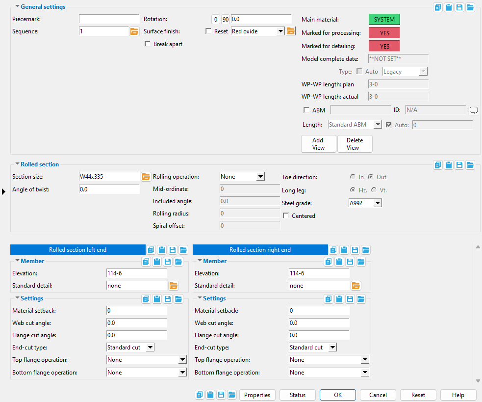
Rolled Section Edit window
( Modeling > F2 > "  Misc steel " > " Rolled Section ")
Selecting " Rolled Section " as the " Miscellaneous steel " type adds a custom member with rolled section material to a 3D model.
The Rolled Section custom member is a superior alternative to " Miscellaneous -- Rolled Section ."
The edit window of this member features material and member options on the same window.
Its " General settings " include " Break apart " and " Rotation " which are not available for the legacy miscellaneous member.


The " OK " button is disabled (grayed out) to indicate a validation error. Hover the " OK " button with your mouse pointer to get a listing of settings you need to change on this window. When all settings are valid, the " OK " button is enabled. 
Red-colored highlighting identifies an entry that is invalid. You need to change that setting, or you will not be able to close this window using " OK ."
Also see :
- Material Types (topic)
- Miscellaneous member types (the complete list)
- Custom members (a rolled section miscellaneous member is a custom member)
- Rolled Section Material (window can set Rolled Section Edit's " Main Material " to ' USER ')
- Miscellaneous members versus legacy miscellaneous members (topic)
- Surfaces Connection (a custom component you can add to a miscellaneous member)
Add a rolled section :
1 . A rolled section miscellaneous member can be properly located and rotated even in an isometric view. Before adding the member, be aware of the following:
- The key to ensuring that a miscellaneous member's material is properly oriented in the model is proper location of the member's work points and proper " Rotation " around the member line established by those work points. The member's material can also be " Centered " with respect to the member line.
- In Modeling , before adding a rolled section miscellaneous member you should Open ( Ctrl + o ) a view that will facilitate the locating of the work points. To lay out a perfectly horizontal rolled section, open a plan view at the desired elevation.
- Work points for a perfectly vertical rolled section can be located in an elevation view .
- Work points for a sloping rolled section -- for example, a section whose member line follows the slope of a roof -- should be added in a view that is at the desired slope. To create such a view, you can use Navigate > Snap to Surface or View > Section View .
2 . To add a rolled section miscellaneous member (in Modeling ):
Alternative 1 : Press F2 > check the box for "
Alternative 2 : Choose Model > Member > Prompt for Member Type > check the box for "
3 . Locate - Repeat - Return mouse bindings become active, and you are prompted to locate the rolled section's work points. Two work points are required to lay out a rolled section.
|
|
|
bindings |
3a : Select the appropriate Locate option.
3b : Left-click ( Locate ) at two different on-screen positions to define the member line between those two points. The first work point you enter when you add the rolled section defines the left end of the member. Both points are represented as exact points after step 4, when the member is actually generated in the model.

The first point that you locate is identified by an origin symbol . The origin symbol also tells you which end is the member's left end. The following illustration shows the difference between locating the two points from left to right versus right to left.
If you Model > Member > Isolate > ... a rolled section miscellaneous member, you will find that the member's MAIN VIEW shows the member's origin symbol (
) to be to your left. This is true for any miscellaneous member -- even if the origin symbol for the member is to your right in a plan view. The MAIN VIEW in member isolation directly correlates to the main view of the miscellaneous member's detail.
Best practice when adding a miscellaneous member in a plan view is to input the member from left to right or from bottom to top. That way, when you add a grid line from left to right, the near side of the member, as determined by the location of its left end , will be the side looking toward the bottom or toward the right of the screen.
4 . The Rolled Section Edit window opens. On it are settings for the rolled section that you are adding.
4a : Enter a " Section size " to define whether the rolled section is a wide flange, angle, channel, W tee, pipe, tube or etc.
4b : Choose a " Rotation " for the rolled section. If, for example, you input a wide flange and accept the default rotation of ' -90 ' degrees, the face of the web rather than the top flange will be parallel to the work plane of your view.
4c : Choose whether or not the material is " Centered " with respect to its member line.
4d ( optional ): The Left/Right End Settings portion of the Rolled Section Material window lets you specify cuts or material setbacks on the ends of the rolled section. The left end is the end associated with the first point you located in step 3.
4e : Press the " OK " button at the bottom of the window to apply your settings and close this window.
Note: The default settings on this window are those of the last rolled section miscellaneous member added or edited in this session of Modeling . Even if all you do is double-click a rolled section member and press " OK " on its edit window, its settings become the defaults for the next-added rolled section miscellaneous member. You therefore only need to make changes to those settings which are different for this member.
5 . If User and Site Options > Modeling > " Process after modeling operation " is ' Process and create solids ', the new section will have automatically undergone all phases of Process and Create Solids and will show up in a solid form . If that option is ' Process ' or ' Do nothing ', then the member line of the rolled section you just added shows up on screen in stick form , and you will have to Process > Process and Create Solids in order to have the member piecemarked and able to be displayed in a solid form. Do one (1) of the following:
|
|
|
bindings |
Alternative 1 : Move the mouse pointer (
) and middle-click ( Repeat ) to lay out a rolled section just like the last one beginning at the point where the point location target (
) is at. The X, Y global axes location of the repeated member will begin from the located repeat point (where the target is at). The section's Z location and other settings will be that of the last-added or last-edited rolled section member.
Alternative 2 : Follow these instructions beginning with step 3 to add a rolled section with different settings than the one you just laid out.
Alternative 3 : Right-click ( Return ) if you are done adding rolled section members.
------ Rolled section ------
Section size: Any section for W , S , L , C , HSS round , HSS rectangular , WT , ST , welded plate W , plate box , beaded flat , rail , cold formed C or cold formed Z material that is listed in the local shape file . You must enter a section size in order to add a rolled section .
C15x50

The selection dialog that opens when you press the button. In this example, only
"To enter a section size: Either type in the section size that you want, or press the "file cabinet" browse button (
Angle of twist: 0 (zero) degrees or the positive or negative (-) number of degrees of twist about the member line of the rolled section.
' 0 ' (zero) results in the member's main material not being twisted.
Entering a ' number of degrees ' causes the left end (the work point #1 end) of the member's main material to remain fixed, while its right end is rotated the number of degrees entered. Validation accepts entries between -3600 and 3600 degrees and can generate twists to as little as .06 degree. Assuming that you are looking from the right end toward the left end of the member, a positive entry rotates the main material counterclockwise.
The following can be used to track the choice made here when " Main material " is ' SYSTEM ':
Report Writer: XXXXX . MaterialTwistAngle
Advanced Selection: MaterialTwistAngle
Parametric module: MaterialTwistAngle
Rolling operation: None or Camber or Weak axis or Strong axis . The center of curvature for each of these choices (except ' None ') is midway between the left and right ends of the member.
None
|
Camber
|
Weak axis
|
Strong axis
|
' None ' makes the rolled section straight (not curved).
' Camber ' produces parabolic bending along the strong axis of the rolled section with the ends fixed. The " Mid-ordinate " sets the offset at mid-span and the direction (+ or -) of that offset.
' Weak axis ' or ' Strong axis ' rolling produces bending that is circular. The two ends of the rolled section are not fixed; that is, if the ends were vertical before the operation, they may not be vertical afterwards. The " Mid-ordinate " or " Included Angle " or " Rolling radius " sets the offset at mid-span and the direction (+ or -) of that offset. A " Spiral offset " may also be set.
The following can report the choice made here when " Main material " is ' SYSTEM ':
Report Writer: XXXXX . RollTypeDescription
Mid-ordinate: The positive or negative (-) distance (in the primary dimension " Units " or other units ) that the rolled section is offset at mid-span as a result of a " Rolling operation " of ' Camber ' or ' Strong Axis ' or ' Weak Axis '. The sign (+ or -) sets the direction of offset.
Camber with a positive mid-ordinate ( +m )
 |
Camber with a negative mid-ordinate ( -m )
 |
| Weak axis rolling with a positive mid-ordinate ( rolling toward the near side ) |
Weak axis rolling with a negative mid-ordinate ( rolling toward the far side )  |
Strong axis rolling with a positive mid-ordinate ( +m )
 |
Strong axis rolling with a negative mid-ordinate ( -m )
 |
The following can be used to track the choice made here when " Main material " is ' SYSTEM ':
Status Display: Member status > Rolling operation and Mid-ordinate
Report Writer: XXXXX . MidOrdinate
Advanced Selection: MidOrdinate
Parametric module: MidOrdinate
Included angle: The positive or negative (-) number of degrees that defines the angle of curvature when the " Rolling operation " is ' Strong Axis ' or ' Weak Axis '. This option applies when " Mid-ordinate " is ' 0 '.
|
i = included angle. Extrapolate a circle from the inside curvature of the member, then draw a line along each end of the member. The lines will meet at the center of the imaginary circle, and their included angle is the angle entered here. |
If the left end of the rolled section is to your left:
A ' positive angle ' raises the center of the rolled section's curvature on your computer screen.
A ' negative (-) angle ' makes the center of the member lower on your computer screen than its two ends.
The following can be used to track the choice made here when " Main material " is ' SYSTEM ':
Report Writer: XXXXX . IncludedAngle
Advanced Selection: IncludedAngle
Parametric module: IncludedAngle
Rolling radius: A positive or negative distance (in the primary dimension " Units " or other units -- up to +/- 120,000 inches) that defines the amount of curvature of the rolled section when the " Rolling operation " is ' Strong axis ' or ' Weak axis '. The smaller the " Rolling radius " (+ or -), the greater the curvature. This option applies if the entries to both the " Mid-ordinate " and " Included angle " are ' 0 '.
|
r = rolling radius. If you were to extrapolate a circle from the inside curvature of the member, the distance from any point on the inside curve of the top/bottom flange to the center of the circle is the distance entered here. |
If the left end (work point 1) of the rolled section is on your left:
A ' positive rolling radius ' raises the center of the center of the section's curvature on your computer screen.
A ' negative (-) rolling radius ' makes the center of the section's curvature lower on your computer screen than its two ends.
The following can be used to track the choice made here when " Main material " is ' SYSTEM ':
Report Writer: XXXXX . RollingRadius
Advanced Selection: RollingRadius
Parametric module: RollingRadius
Spiral offset: The positive or negative (-) distance (in the primary dimension " Units " or other units ) that you want the right end of the rolled section to be offset from the left end. The left end of the rolled section remains fixed. This applies when the " Rolling operation " is ' Weak axis ' or ' Strong axis ', and a non-zero entry has been made to the " Mid-ordinate ," " Included angle ," or the " Rolling Radius " fields.
For a rolled section whose member line is in the work plane of a plan view:
A ' positive distance ' raises the right end.
A ' negative (-) distance ' lowers the right end.
Tip: You might, for instance, use this option to create a stringer for a spiral stair.
The following can be used to track the choice made here when " Main material " is ' SYSTEM ':
Report Writer: XXXXX . SpiralOffset
Advanced Selection: SpiralOffset
Parametric module: SpiralOffset
Toe direction: In or Out . This applies to channel and angle sections.
' In ' signifies toe in. When facing the near side of the channel or angle (the near side is the side where the member's left end is to your left), the flange(s) of the angle or channel point toward you when ' In ' is selected.
' Out ' signifies toe out. If you are viewing the near side of the channel or angle, the flange(s) point away from you when ' Out ' is selected.
The following can be used to track the choice made here when " Main material " is ' SYSTEM ':
Status Display: Material status > Channel toe direction
Report Writer: XXXXX . Material.ToeInOrOutDescription
Advanced Selection: ToeInOrOut
Parametric module: ToeInOrOut
Long leg: Horizontal or Vertical . This applies to angles with legs of unequal length.
' Horizontal ' specifies that the long leg of the angle is horizontal.
' Vertical ' specifies that the long leg of the angle is vertical.
The following can be used to track the choice made here when " Main material " is ' SYSTEM ':
Status Display: Material status > Angle long leg orientation
Report Writer: XXXXX . IsLongLegVertical
Steel grade: A36 or A572 or etc. This is the steel grade for the " Section size " entered above.
Setup: If the grade of steel you want is not shown on the list box (
) for this field, you can use Home > Project Settings > Job > Wide Flange Grades or WT Grades or Channel Grades or Angle Grades or Pipe Grades or HSS / TS Grades to add it to the list.
Tip: Changing the " Steel grade " does not cause a material to be regenerated. This means that, if you change this setting only, material operations such as a Cut Layout may, optionally, be preserved.
The following can be used to track the choice made here when " Main material " is ' SYSTEM ':
Report Writer: MemberMaterial.Material.SubMaterial.MaterialGradeDescription
Advanced Selection: MaterialGrade
Parametric module: MaterialGrade
If this box is checked (
If the box is not checked (
), the rolled section is to one side of its member line.
|
|
|
------ Member ------
End elevation: The elevation (in the primary dimension " Units " or other units ) of the work point at this end of the rolled section. For a non-sloping section, both the left and right end elevations are the same. When you add the rolled section, its work points are placed in your current view's reference elevation until you change their elevations here, on this window. Work points are aligned with the top of the rolled section.
| A rolled section has two exact points , whose elevation you can change by changing the plate's left- and/or right-end " End elevation ." |
|
To determine the end elevation on a rolled section in the 3D model, use Construction Line Add or a similar tool, select EXPT as the Locate option, then snap the point location target to the work point at the end of the member. The Z coordinate reported in the X-Y-Z display tells you the elevation at the snapped-to exact point.
Tip: You should use this option instead of rotating a rolled section member's material to change its left- or right-end elevation. For complex situations, you can Model > Member > Move/Stretch one or the other of its work points.
Standard detail: None or a standard detail name . To apply a standard detail, you can type in the file name of the drawing (if you know it), or press the "file cabinet" browse button ( ![]() ) and double-click any job standard detail or global standard detail that is on the list.
) and double-click any job standard detail or global standard detail that is on the list.
If ' none ' is entered here, then no standard detail will be applied on this end of the miscellaneous member when it is automatically detailed .
If a ' standard detail name ' is entered here, the next time you auto detail this miscellaneous member, the reference point of the standard detail will align with the input work point on this end of the member, and the standard detail's bill of material will be combined with the member's bill of material. The detail is placed on a layer that is named after the standard detail plus a "_L" or "_R" suffix.
------ Settings ------
Material setback: The positive or negative distance in the primary dimensioning " Units " that you want the (left or right) end of the rolled section to be displaced from its work point.
A ' positive material setback ' makes the material shorter. The distance is subtracted from the distance spanned by the section's member line to give you the length of the section.
A ' negative (-) material setback ' makes the rolled section longer. The distance is also subtracted from the distance spanned by the section's member line to give you the length of the section.
The following can be used to track the choice made here when " Main material " is ' SYSTEM ':
Report Writer: XXXXX . MaterialSetbackLeftEnd
Report Writer: XXXXX . MaterialSetbackRightEnd
Advanced Selection: MaterialSetback[0] or MaterialSetback[1]
Parametric module: MaterialSetback[0] or MaterialSetback[1]
Web cut angle: A positive or negative (-) angle from 89 to -89 degrees.
| left | right | left & right | left | right |
-10 degrees
 |
-10 degrees
 |
0 degrees
 |
10 degrees
 |
10 degrees
 |
An entry of ' 0 ' (zero) designates that no web cut be made. Assuming, for example, that the left end of the web of the member is to your left on screen and that the member's bottom flange is toward the bottom of the screen: a ' positive angle ' is measured counterclockwise from a perpendicular bisector to the member line; a ' negative (-) angle ' is measured clockwise from a perpendicular bisector to the work line.
The following can be used to track the choice made here when " Main material " is ' SYSTEM ':
Report Writer: XXXXX . WebCutLeftEnd
Report Writer: XXXXX . WebCutRightEnd
Advanced Selection: WebCutEnd[0] or WebCutEnd[1]
Parametric module: WebCutEnd[0] or WebCutEnd[1]
Flange cut angle: A positive or negative (-) angle from 89 to -89 degrees. The flange is cut at this angle across its entire width.
| wide flange | ||||
| left | right | left & right | left | right |
-10 degrees
 |
-10 degrees
 |
0 degrees
 |
10 degrees
|
10 degrees
 |
| angle (or channel) | ||||
| left | right | left & right | left | right |
-10 degrees
 |
-10 degrees
 |
0 degrees
 |
10 degrees
 |
10 degrees
 |
An entry of ' 0 ' (zero) designates no flange cut. Assuming that the left end of the member's top flange is to your left, a ' positive angle ' is measured counterclockwise from a perpendicular bisector to the top flange center line. A ' negative (-) angle ' is measured clockwise from a perpendicular bisector to the top flange center line.
Note: This operation functions in a different way when " Top/Bottom flange operation " is set to ' Clip flange '.
The following can be used to track the choice made here when " Main material " is ' SYSTEM ':
Report Writer: XXXXX . FlangeCutLeftEnd
Report Writer: XXXXX . FlangeCutRightEnd
Advanced Selection: FlangeCutEnd[0] or FlangeCutEnd[1]
Parametric module: FlangeCutEnd[0] or FlangeCutEnd[1]
End-cut type: Standard cut or Square cut or Bevel cut or Mill cut .
|
If ' Standard cut ' is selected and the rolled section you are editing is member main material, the member detail is not annotated with special cut instructions. The designation ' None ' is entered to the " End Prep " column on an ABM Report for member main materials with a ' Standard cut ' selected on both ends.
Selecting ' Square cut ' for the end of a member main material adds instructions to "SQ CUT" (as illustrated above) when the member is detailed. The instruction ' S1E ' is entered to the " End Prep " column on an ABM Report for member main materials with a ' Square cut ' on one end.
Selecting ' Bevel cut ' for the end of a member main material adds instructions on the subsequently generated member detail to "BEV CUT" that end. The instruction ' B2E ' is entered to the " End Prep " column on an ABM Report for member main materials with a ' Bevel cut ' on both ends. ' Bevel cut ' is automatically selected on main material for sloping beam-to-beam connections or sloping beam-to-column connections, column-to-sloping beam connections, and beam-to-rotated beam connections. ' Bevel cut ' indicates that the " Web cut angle " is a value other than zero.
' Mill cut ' for a member main material instructs Detail Members to apply the annotation "MILL CUT" to the appropriate end on the member detail. The instruction ' M2E ' is entered to the " End Prep " column on an ABM Report for member main materials whose both ends are ' Mill cut '. When the option " Mill cut ends of columns " is checked, ' Mill cut ' is automatically applied to the ends of columns framing squarely to other members or to base plates.
The following can be used to track the choice made here when " Main material " is ' SYSTEM ':
Report Writer: Member.LeftEnd.MoreEnd.EndPreparationDescription
Advanced Selection: EndPreparation[0] or EndPreparation[1]
Parametric module: EndPreparation[0] or EndPreparation[1]
Top/bottom flange operation: None or Cope plain or Cope shop weld #3 (Standard) or Cope field weld #3 (Standard) or Cut flange width or Cut flange flush or Clip flange or Notch top/bottom or Notch near side/far side or Cope field weld #1 (FEMA) or Cope shop weld #1 (FEMA) or Clip web or Seismic cope field weld or Seismic cope shop weld . Also click here .
Tip: The DSTV " CNC configuration type " can CNC download any weld preparation set here.
Also: " Add holes " in CNC Setup has options for putting holes in cope radii.
The following can be used to track the choice made here when " Main material " is ' SYSTEM ':
Advanced Selection: TopOperationTypeLeftEnd or TopOperationTypeRightEnd or BottomOperationTypeLeftEnd or BottomOperationTypeRightEnd
Parametric module: TopOperationTypeLeftEnd or TopOperationTypeRightEnd or BottomOperationTypeLeftEnd or BottomOperationTypeRightEnd' None ' designates that no top/bottom flange cutting operation be performed on this member's main material.
' Cope plain ' or ' Cope shop weld #3 (Standard) ' or ' Cope field weld #3 (Standard) designates weld preparation and / or a cut to remove part of the top/bottom flange plus part of the web. ' Cope shop weld #3 (Standard) ' or ' Cope field weld #3 (Standard) ' work best for wide flange or S shape or W tee or S tee material; ' Cope plain ' works for all material types. Tip : A " Cope length " of ' 0 ' for ' Cope shop weld #3 (Standard) ' or ' Cope field weld #3 (Standard) ' gives you weld preparation without a coping operation. CNC : " Add holes " in CNC Setup can be set to ' In copes ' or ' In all radii ' to download the cope hole (or weld prep hole).
" Cope length " is the distance parallel with main material's longitudinal axis ( X material axis ) from the (left or right) end of the member to the flange. Entries must either be ' 0 ' or greater than or equal to '1/2' inch ('13' mm).
" Cope depth " is the distance from the top of the top flange (or bottom of the bottom flange) into the web of the material. The cope depth is measured parallel with the " Web cut " angle, or -- for ' Cope plain ', if the " Cope cut type " is ' Parallel to flange ' -- it is measured perpendicular to the flange.
" Cope radius " sets the curvature at the corner for a " Cope plain " operation. The " Cope depth " must be, at least, the flange thickness plus the " Cope radius ." If you try to enter a " Cope depth " that is less than this minimum, your entry will be changed to the minimum.
" Clip web " is an option when ' Cope shop weld #3 (Standard) ' is the selected " Top/bottom flange operation ."
" Groove angle " sets the angle of the flange bevel to anywhere within the allowable limit of +/- 75 degrees.
' Cut flange width ' is for wide flange or S shape or W tee or S tee sections (illustrated below). It applies flange cuts on both the near side and the far side of the web. For channel or angle material, it designates a single cut (on the flange or on one leg of the angle) and you need only enter " Flange length NS " if the material is toe in, " Flange length FS " if the material is toe out.
The ' Top/Bottom flange length NS ' is the distance from the (left or right) end of the material along the length of the near side of the top/bottom flange
The ' Top/Bottom flange length FS ' is the distance from the (left or right) end of the material along the length of the far side of the top flange.
The ' Top/Bottom flange width ' is the flange width that remains after the NS and FS flange cuts are made.
' Cut flange flush ' is for wide flange or S shape or W tee or S tee material. It applies two flange cuts, one on the near side and the other on the far side of the flange, both cuts to the web. Entering zero (0) to the ' Length NS ' or ' Length FS ' field means that no cut is made at that location. For channel or angle material, it designates a single cut (on the flange or on one leg of the angle) and you need only enter " Flange length NS " if the material is toe in, " Flange length FS " if the material is toe out.
' Top/Bottom flange length NS ' is the distance from the (left or right) end of the material along the material's longitudinal axis ( X material axis ).
' Top/Bottom flange length FS ' is the distance from the (left or right) end of the material along the material's longitudinal axis ( X material axis ).
' Clip flange ' is for a wide flange or S shape or W tee or S tee " Section size ." It applies a linear cut from the edge of the flange to the radius of the web at the " Flange cut angle ." If the " Flange cut angle " is ' 0 ' or the " Section size " is angle, pipe, tube, or channel, then a ' Clip flange ' does not take place.
|
| In this example, the " Flange cut angle " is positive. The clip on the left end is on the near side of the flange. The clip on the right end is on the far side. |
' Notch top ' or ' Notch bottom ' gives you distance entry fields for " Notch length " and " Notch width " and " Notch radius " and " Notch offset " that let you define the dimensions for a cut from the left/right edge of the HSS rectangular or HSS round material into the center of the material's top or bottom wall.
|
| Enter a " Notch radius " other than ' 0 ' and set " Add holes " for ' in all radii ' in CNC Setup to have your CNC machine punch/drill the hole at the end of the slot. |
The following can accurately track the choice made here when " Main material " is ' SYSTEM ':
Advanced Selection: TopLengthLeft or etc. (" Notch length ")
Advanced Selection: TopWidthLeft or etc. (" Notch width ")
Advanced Selection: left_top_op_dim3 or etc. (" Notch radius ")
Advanced Selection: left_top_op_dim4 or etc. (" Notch offset ")Parametric module: TopLengthLeft or etc. (" Notch length ")
Parametric module: TopWidthLeft or etc. (" Notch width ")
Parametric module: left_top_op_dim3 or etc. (" Notch radius ")
Parametric module: left_top_op_dim4 or etc. (" Notch offset ")' Notch near side ' or ' Notch far side ' gives you distance entry fields for " Notch length " and " Notch width " and " Notch radius " and " Notch offset " that let you define the dimensions for a cut from the left/right edge of the HSS rectangular or HSS round material into the center of the material's near side or far side wall.
The following can accurately track the choice made here when " Main material " is ' SYSTEM ':
Advanced Selection: TopLengthLeft or etc. (" Notch length ")
Advanced Selection: TopWidthLeft or etc. (" Notch width ")
Advanced Selection: left_top_op_dim3 or etc. (" Notch radius ")
Advanced Selection: left_top_op_dim4 or etc. (" Notch offset ")Parametric module: TopLengthLeft or etc. (" Notch length ")
Parametric module: TopWidthLeft or etc. (" Notch width ")
Parametric module: left_top_op_dim3 or etc. (" Notch radius ")
Parametric module: left_top_op_dim4 or etc. (" Notch offset ")' Cope field weld #1 (FEMA) ' gives you distance entry fields for " Cope length ," " Re-entrant cut length ," " Re-entrant cut depth " " Flange flush length " " Re-entrant radius " " Groove angle ."
Setup: " Alternate 1 re-entrant cut radius " " Groove angle " " Alternate 1 re-entrant cut length " " Alternate 1 re-entrant cut depth " " Alternate 1 flange flush length ."
CNC: " Add holes " in CNC Setup can be set to ' In copes ' or ' In all radii ' to download the weld prep hole.The following can track the choice made here when " Main material " is ' SYSTEM ':
Advanced Selection: TopLengthLeft or etc.(" Cope length ")
Advanced Selection: TopFEMAReEntrantLengthLeft or etc. (" Re-entrant length ")
Advanced Selection: TopFEMAReEntrantDepthLeft or etc. (" Re-entrant depth ")
Advanced Selection: TopFEMAFlangeFlushLengthLeft or etc. (" Flange flush length ")
Advanced Selection: TopReEntrantRadiusLeft or etc. (" Re-entrant radius ")
Advanced Selection: TopGrooveAngleLeft or etc. (" Groove angle ")
Advanced Selection: TopReEntrantHoleDistanceLeft or etc. (" Re-entrant hole distance ")Parametric module: TopLengthLeft or etc.(" Cope length ")
Parametric module: TopFEMAReEntrantLengthLeft or etc. (" Re-entrant length ")
Parametric module: TopFEMAReEntrantDepthLeft or etc. (" Re-entrant depth ")
Parametric module: TopFEMAFlangeFlushLengthLeft or etc. (" Flange flush length ")
Parametric module: TopReEntrantRadiusLeft or etc. (" Re-entrant radius ")
Parametric module: TopGrooveAngleLeft or etc. (" Groove angle ")
Parametric module: TopReEntrantHoleDistanceLeft or etc. (" Re-entrant hole distance ")' Cope shop weld #1 (FEMA) ' gives you distance entry fields for " Cope length ," " Re-entrant cut length ," " Re-entrant cut depth " " Clip web " " Flange flush length " " Re-entrant radius " " Groove angle " and " Re-entrant hole distance ."
Setup: " Alternate 1 re-entrant cut radius " " Groove angle " " Alternate 1 re-entrant cut length " " Alternate 1 re-entrant cut depth " " Alternate 1 flange flush length ."
CNC: " Add holes " in CNC Setup can be set to ' In copes ' or ' In all radii ' to download the weld prep hole.
The following can accurately reveal the choice made here when " Main material " is ' SYSTEM ':
Advanced Selection: TopLengthLeft or etc.(" Cope length ")
Advanced Selection: TopFEMAReEntrantLengthLeft or etc. (" Re-entrant length ")
Advanced Selection: TopFEMAReEntrantDepthLeft or etc. (" Re-entrant depth ")
Advanced Selection: TopFEMAClipLeft or etc. (" Clip web ")
Advanced Selection: TopFEMAFlangeFlushLengthLeft or etc. (" Flange flush length ")
Advanced Selection: TopReEntrantRadiusLeft or etc. (" Re-entrant radius ")
Advanced Selection: TopGrooveAngleLeft or etc. (" Groove angle ")
Advanced Selection: TopReEntrantHoleDistanceLeft or etc. (" Re-entrant hole distance ")Parametric module: TopLengthLeft or etc.(" Cope length ")
Parametric module: TopFEMAReEntrantLengthLeft or etc. (" Re-entrant length ")
Parametric module: TopFEMAReEntrantDepthLeft or etc. (" Re-entrant depth ")
Parametric module: TopFEMAClipLeft or etc. (" Clip web ")
Parametric module: TopFEMAFlangeFlushLengthLeft or etc. (" Flange flush length ")
Parametric module: TopReEntrantRadiusLeft or etc. (" Re-entrant radius ")
Parametric module: TopGrooveAngleLeft or etc. (" Groove angle ")
Parametric module: TopReEntrantHoleDistanceLeft or etc. (" Re-entrant hole distance ")Clip web gives you distance entry fields for " Clip length " and " Clip depth ." This operation works well on channel sections, such as the stair stringer illustrated below.
A channel stair stringer with a cut generated by selecting ' Bolt to Floor ' as the " End condition ." The following can reliably output the choice made here when " Main material " is ' SYSTEM ':
Advanced Selection: TopLengthLeft or etc. (" Clip length ")
Advanced Selection: TopClipLeft or etc. (" Clip depth ")Parametric module: TopLengthLeft or etc. (" Clip length ")
Parametric module: TopClipLeft or etc. (" Clip depth ")' Seismic cope field weld ' gives you distance entry fields for " Cope length ," " Re-entrant length ," " Re-entrant depth " " Clip web " " Flange flush length " " Re-entrant radius " " Groove angle " and " Re-entrant hole distance ."
Setup: Seismic Weld Access Holes .
CNC: " Add holes " in CNC Setup can be set to ' In copes ' or ' In all radii ' to download the weld prep hole.
The following can reliably track the choice made here when " Main material " is ' SYSTEM ':
Advanced Selection: TopLengthLeft or etc.(" Cope length ")
Advanced Selection: TopFEMAReEntrantLengthLeft or etc. (" Re-entrant length ")
Advanced Selection: TopFEMAReEntrantDepthLeft or etc. (" Re-entrant depth ")
Advanced Selection: TopFEMAFlangeFlushLengthLeft or etc. (" Flange flush length ")
Advanced Selection: TopReEntrantRadiusLeft or etc. (" Re-entrant radius ")
Advanced Selection: TopGrooveAngleLeft or etc. (" Groove angle ")
Advanced Selection: TopReEntrantHoleDistanceLeft or etc. (" Re-entrant hole distance ")Parametric module: TopLengthLeft or etc.(" Cope length ")
Parametric module: TopFEMAReEntrantLengthLeft or etc. (" Re-entrant length ")
Parametric module: TopFEMAReEntrantDepthLeft or etc. (" Re-entrant depth ")
Parametric module: TopFEMAFlangeFlushLengthLeft or etc. (" Flange flush length ")
Parametric module: TopReEntrantRadiusLeft or etc. (" Re-entrant radius ")
Parametric module: TopGrooveAngleLeft or etc. (" Groove angle ")
Parametric module: TopReEntrantHoleDistanceLeft or etc. (" Re-entrant hole distance ")' Seismic cope shop weld ' gives you distance entry fields for " Cope length ," " Re-entrant length ," " Re-entrant depth " " Clip web " " Flange flush length " " Re-entrant radius " " Groove angle " " Re-entrant hole distance ."
Setup: Seismic Weld Access Holes .
CNC: " Add holes " in CNC Setup can be set to ' In copes ' or ' In all radii ' to download the weld prep hole.
The following can be used to track the choice made here when " Main material " is ' SYSTEM ':
Advanced Selection: TopLengthLeft or etc.(" Cope length ")
Advanced Selection: TopFEMAReEntrantLengthLeft or etc. (" Re-entrant length ")
Advanced Selection: TopFEMAReEntrantDepthLeft or etc. (" Re-entrant depth ")
Advanced Selection: TopFEMAClipLeft or etc. (" Clip web ")
Advanced Selection: TopFEMAFlangeFlushLengthLeft or etc. (" Flange flush length ")
Advanced Selection: TopReEntrantRadiusLeft or etc. (" Re-entrant radius ")
Advanced Selection: TopGrooveAngleLeft or etc. (" Groove angle ")
Advanced Selection: TopReEntrantHoleDistanceLeft or etc. (" Re-entrant hole distance ")Advanced Selection: TopLengthLeft or etc.(" Cope length ")
Advanced Selection: TopFEMAReEntrantLengthLeft or etc. (" Re-entrant length ")
Advanced Selection: TopFEMAReEntrantDepthLeft or etc. (" Re-entrant depth ")
Advanced Selection: TopFEMAClipLeft or etc. (" Clip web ")
Advanced Selection: TopFEMAFlangeFlushLengthLeft or etc. (" Flange flush length ")
Advanced Selection: TopReEntrantRadiusLeft or etc. (" Re-entrant radius ")
Advanced Selection: TopGrooveAngleLeft or etc. (" Groove angle ")
Advanced Selection: TopReEntrantHoleDistanceLeft or etc. (" Re-entrant hole distance ")More on top/bottom flange operations:
ok = operation works well on specified material
n/a = operation not applicable for that materialW , S C L ** tube pipe WT ** None ok ok ok + ok ok ok + Cope plain ok ok ok + ok ok ok + Cope field #3 ok - - n/a n/a ok Cope shop #3 ok - - n/a n/a ok Cut flange width ok ok * ok * n/a n/a ok Cut flange flush ok ok * ok * n/a n/a ok Clip flange ok n/a n/a n/a n/a ok Notch top/bottom n/a n/a n/a ok ok n/a Notch NS/FS n/a n/a n/a ok ok n/a Cope field #1 ok - - n/a n/a ok Cope shop #1 ok - - n/a n/a ok Clip web - ok - n/a n/a - ** = operations only work on top flange unless marked with +
+ = operation may be applied to the bottom of the stem
* = enter "Flange length NS" for toe in, "...FS" for toe out

