Hand Rail member
See on another page: Handrail add.
- Tool Summary
- Tips and Tricks
- Related Tools
Overview Tab
Piecemark: Blank or a system piecemark or a user-entered character string (of up to 61 characters ) which identifies this member as having an unique design distinct from other members that have been assigned different piecemarks. This is the member piecemark of the handrail member.
Blank instructs SDS2 piecemarking to assign a system piecemark to the handrail member when you press " OK " to close this window.
" Piecemark " is, by default, left blank when you first add a new handrail.A system piecemark ( system piecemark ) is assigned automatically if " Piecemark " is blank when you press " OK ." SDS2 piecemarking uses the prefix that is entered to " Piecemark " on the Hand Rail Setup window.
A user-entered string is a user piecemark . SDS2 piecemarking will not assign new members that user piecemark, nor will piecemarking remove that user piecemark from members to which it has been assigned. It is your responsibility to ensure that the same user piecemark is not used for another distinctly different member.
Tip: If you have assigned a user piecemark to the handrail member, clearing that piecemark and leaving " Piecemark " blank will result in piecemarking assigning a system piecemark to the member when you press " OK ."
Setup For Add Flat Rail:Hand Rail Setup
Display Options:Member piecemarks
Status Display:General status options > Piecemark
Advanced Selection:m.Piecemark
Advanced Selection:m.SystemPiecemark
Sequence: Any sequence name from the Sequence Names setup list can be selected here.
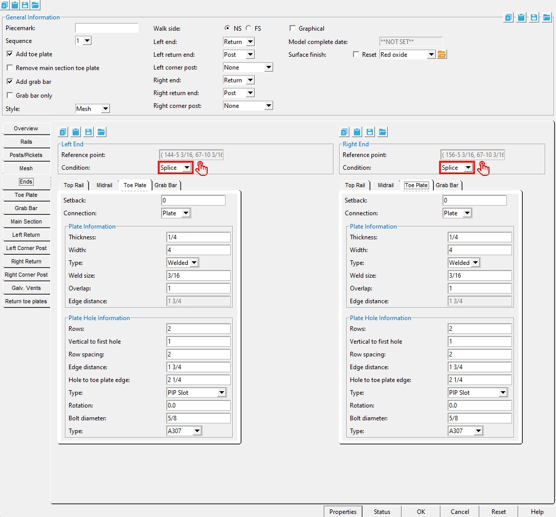
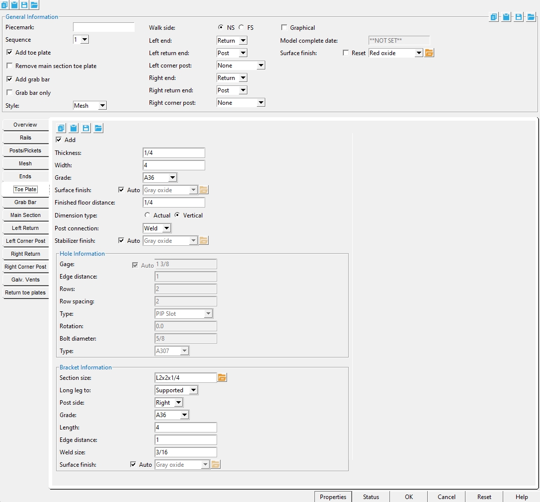
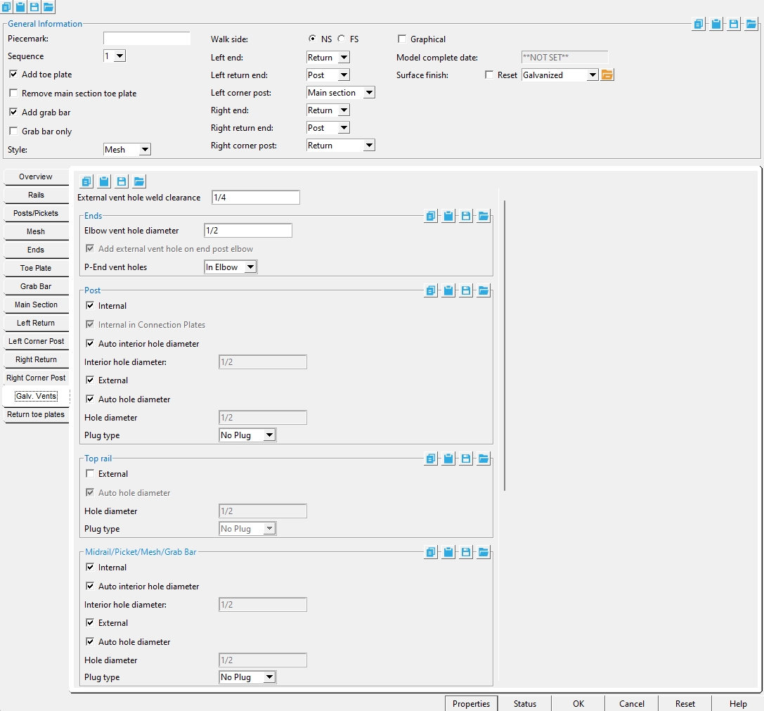
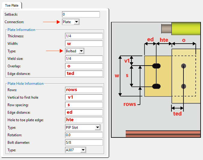
Add toe plate:
![]() or
or ![]() . Same as " Add " under the " Toe Plate " tab.
. Same as " Add " under the " Toe Plate " tab.
If this box is checked (
), then " Add " is checked under the " Toe Plate " tab and the options shown above are enabled.
If the box is not checked (
), then " Add toe plate " is not checked and the options shown above are not enabled.
Remove main section toe plate:
![]() or
or ![]() . This option is enabled when " Add toe plate " is checked. It is disabled when " Add toe plate " is unchecked.
. This option is enabled when " Add toe plate " is checked. It is disabled when " Add toe plate " is unchecked.
If this box is checked (
If the box is not checked (
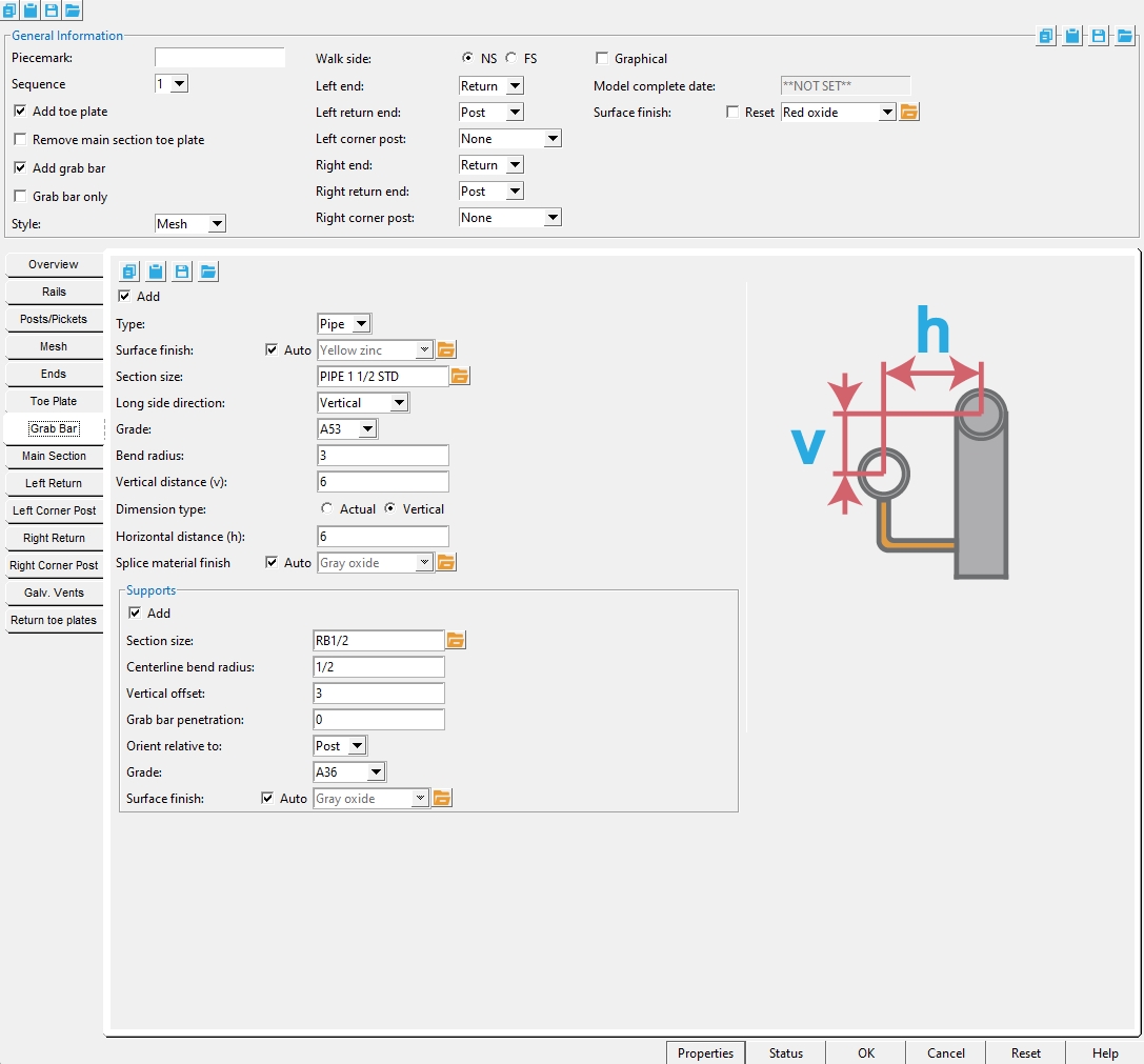
Add grab bar:
![]() or
or ![]() . Same as " Add " under the " Grab Bar " tab. This option is disabled (grayed out) when the post " Type " is ' Angle '.
. Same as " Add " under the " Grab Bar " tab. This option is disabled (grayed out) when the post " Type " is ' Angle '.
If this box is checked (
If the box is not checked (
Grab bar only: ![]() or
or ![]() . This applies when "
. This applies when " ![]() Add grab bar " is checked.
Add grab bar " is checked.
If this box is checked (
If the box is not checked (
Style: Empty or Mesh or Pickets . These options apply when the post material " Type " is ' Pipe ' or ' Tube '. You cannot apply mesh or pickets when the post
' Empty '
|
' Mesh '
|
' Pickets '
|
If ' Empty ' is selected, mesh or pickets do not get added.
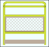
If ' Mesh ' is selected, mesh is added per the " Mesh " tab.
If ' Pickets ' is selected, the " Max clearance " and " Type " and " Grade " settings under the " Pickets " tab will be applied to the pickets that are generated. Picket length depends on the midrail " Count ."
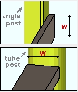
Walk side: NS (near side) or FS (far side). This sets the side of the " Toe plate " and the " Grab bar . For angle handrails, it sets the leg orientation. Click here for information on how to determine the near side and far side of a member.
' NS '

' FS '
' NS '
' FS '
On an angle handrail (as shown in the example immediately above), the heel of the top rail (and angle midrails) align with the work line regardless of the choice made here. ' NS ' sets the direction of the horizontal leg of the top rail away from the near side , and the angle posts align in that same direction. ' FS ' sets the horizontal leg direction toward the near side.
Left end: P-End or Post or Return or Splice . This sets the main section end " Condition " for the " Left End " under the " Ends " tab.
Left return end: P-End or Post or Splice . This applies when the main section end " Condition " for the " Left End " is ' Return '. The end " Condition " for the return is set under " End Information ."
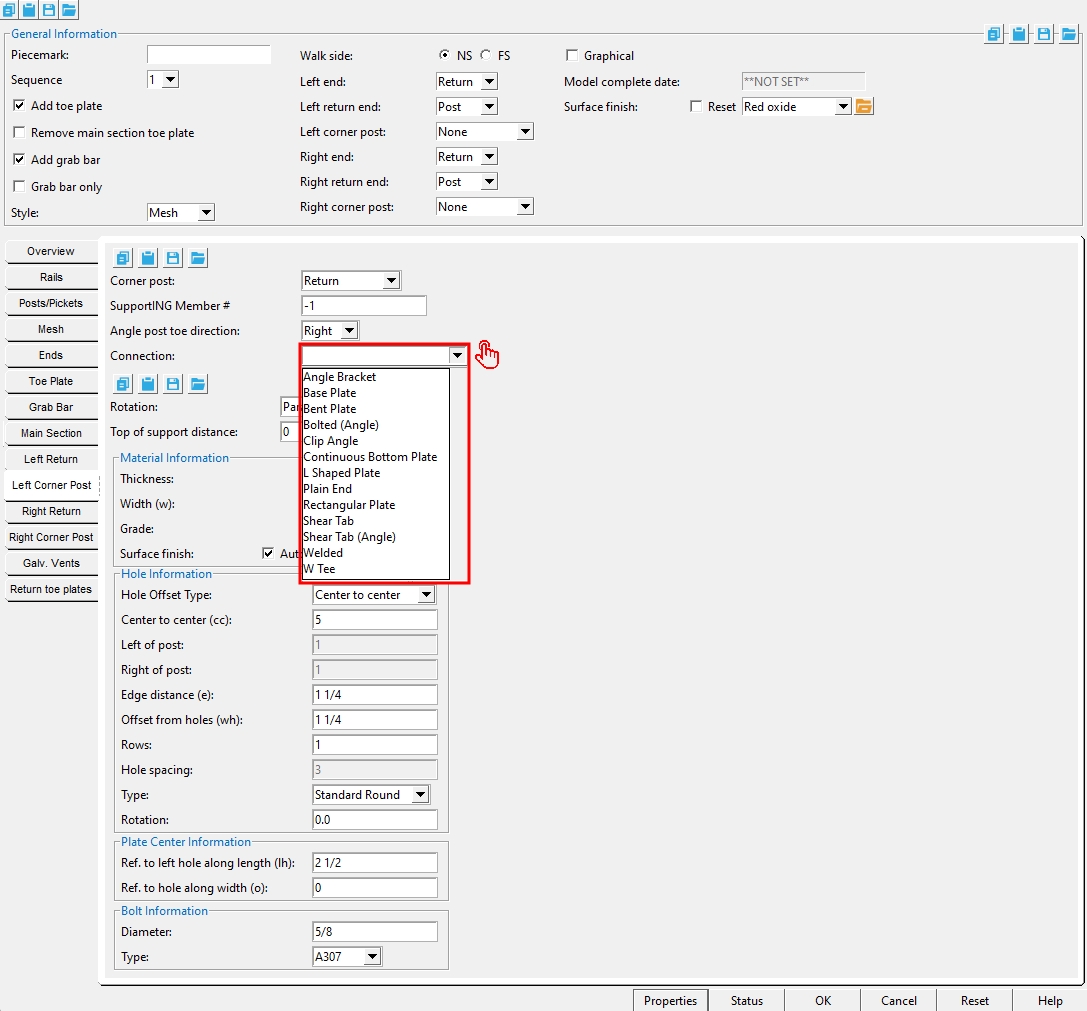
Left corner post: None or Main section or Return . Documentation in progress . This applies when the main section end " Condition " for the " Left End " is ' Return '. This also sets the " Corner post " on the corresponding " Left Corner Post " tab. Choosing either ' Main section ' or ' Return ' gives the corner post connection settings that match that section. For example, a ' Base Plate ' post connection will get the same " Top of support distance " the section you chose. Choosing ' Main section ' or ' Return ' also adds an entry for that member on that section's Intermediate Posts table.
Right end: This sets " Condition " for the " Right End " of the main section (under the " Ends " tab ).
Right return end: This applies when the " Condition " for the " Right End " of the main section is ' Return '. It sets the end " Condition " for the return, which can also be set under " End Information ."
Right corner post: None or Main section or Return. This applies when the main section end " Condition " for the " Right End " is
If the box is checked (
If the box is not checked (
Note: Add Material or Add Hole or Add Bolt does not change the member to graphical (
Model complete date: Read-only . The " Model completed " status of this member can be set using Update Attributes . You cannot set the " Model complete date " here, on this window.
**NOT SET** ' indicates that this window is fully editable.
month day year ' indicates that all fields on this window are in a disabled , read-only state due to the " Model completed " date having been set on this member, using Update Attributes , not necessarily on the reported date.
Also see: " Model complete date "
Surface finish: None or Sandblasted or Red oxide or Yellow zinc or Gray oxide or Blued steel or Galvanized or Duplex Coating or Undefined 1 or Undefined 2 or Undefined 3 or Red oxide 2 or Any user added surface finish. This affects the colors of Solid members on erection views in the Drawing Editor . This also sets the color when Output material color is set to Surface finish for a VRML Export or a DWG/DXF Export. The Color (not Surface finish) sets the color of this material in Modeling .
| sand blasted | red oxide | yellow zinc | user surface finish 1 |
| gray oxide | blued steel | galvanized | user surface finish 2 |
To assign a different surface finish, you can drop-down the current surface finish and select the one you want, or you can press the
browse button and double-click any surface finish that is on the list.
Auto ![]() or
or ![]()
If this box
If the box
Note 1: Submaterial piecemarks can be split apart by surface finish. All surface finishes that do not have the Break Marks Material checked on can be applied to any like material with out the material splitting. If the Break Marks Material is checked on then only like materials with that specific surface finish can have the same piecemark, and because the submaterial marks differ so would the member's piecemark.
Note 2: When exporting a KISS file using "model" as the Data source surface finish data on the materials are compiled into the KISS download as follows, with a few exceptions (G=galvanized, N= none or sandblasted, P= others). Those exceptions are:
If the box for Finish routing in KISS export setup is set to a user routing
If the user has adjusted the Abbreviation for any of the default provided surface finishes
If you are using a user added surface finish
In these cases you will get what is provided in either the User routing, or the abbreviation field. For other exports it will always provide the abbreviation in the 'surface finishes' settings page.
Tip 1: Surface area is reported on the General Information window -- and this can be used to estimate the amount of coating required and its cost.
Tip 2: Changing Steel grade, Color, and Surface finish do not cause the plate to be regenerated. This means that, if you change those settings only, material fit operations such as a Fit Exact may optionally be preserved.
Report Writer: MemberMaterial.Material.SurfaceFinish
Setup: Surface Finish Settings
Properties opens the Edit Properties window, on which you can make entries to custom properties. If your current Job was set to use a legacy flavor when it was created, the window that opens is named Custom Properties , not Edit Properties.
Tip: The Edit Properties window can also be used to read
Log entries or review or type
Tip: The Member Properties command is an alternative to this button. It opens the Edit Properties window directly, without your first having to open a member edit window.
Status opens the Member Status Review window, which can give you additional information about the member, and which you can use to enter status information or designate a member as an existing member.
Note: This button shows
if one or more Repeat check boxes on the Member Status Review window do not match the checked-unchecked state of same-named fields in User and Site Options > Site > Member status items to copy/repeat. On the Status Review window, the fields that do not match User and Site Options are plotted in red .
OK (or the Enter key) closes the edit window and saves any changes you have made on the window to the member file.
Solids on OK: If the appropriate choice is made to User and Site Options > Modeling > Automatically process after modeling operation, then this member will automatically be regenerated (Create Solids will take place) after your press OK. Otherwise, you will have to manually Process and Create Solids in order for changes you made on this window to be fully updated in the 3D model.
Change all: If you Edit Member (one member only) and make a change that potentially triggers the Do you want to change all ... dialog and the 3D model contains more than one member of the same type that has the same piecemark as the member you changed, a yes-no dialog opens. On it is the question, Do you want to change all (members with this piecemark). Press the Yes button to change all the members; press the No button to change only this member.
Cancel (or the Esc key or the ![]() button) closes the edit window without saving any changes that you have made. Cancel does not undo a Detail Member operation.
button) closes the edit window without saving any changes that you have made. Cancel does not undo a Detail Member operation.
Note: If you opened this window while adding a member, Cancel brings you back to the work point location step of adding a member.
Tip: Any time you use Edit Member just to review a member (and you do not want to set the defaults for to-be-added members), the best way to close this window is to Cancel.
Reset undoes any changes made since you opened this window.
Exception: Reset does not undo changes made using the Add View, Delete View, Detail Member, and View detail buttons.
![]() Copy, Paste, Save, Load buttons:
Copy, Paste, Save, Load buttons:
- The position of these "form" buttons on the window tells you what settings they apply to. Click here for more information.
- You can
 Copy the settings on this window, then
  Paste those settings to a different edit window of the same type.
- You can
 Save the settings on this window to a file stored in a global folder that is used by your current version of SDS2. Give the file a name that will help other users identify its purpose. You can Load a saved file to replace the settings on this window (except Piecemark) with the settings that are stored in the file you select.
- When editing multiple windows at the same time, Paste and Load replace mixed entries to a single field with a single entry. Copy and Save ignore fields with mixed entries, treating them as if they have no entry or do not exist.
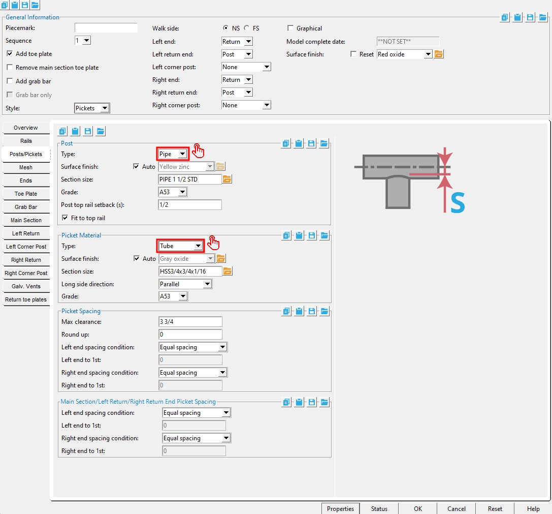
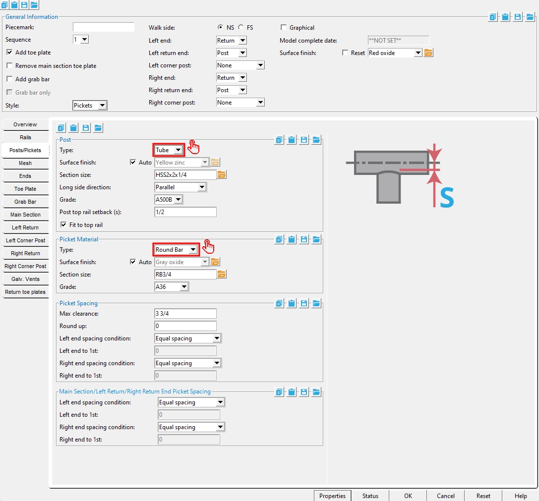
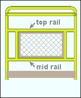
Top Rail/Post/Midrail Overview
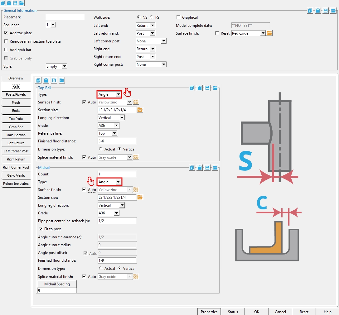
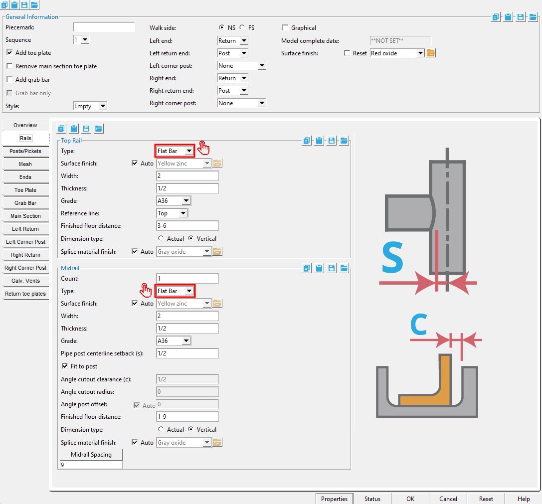
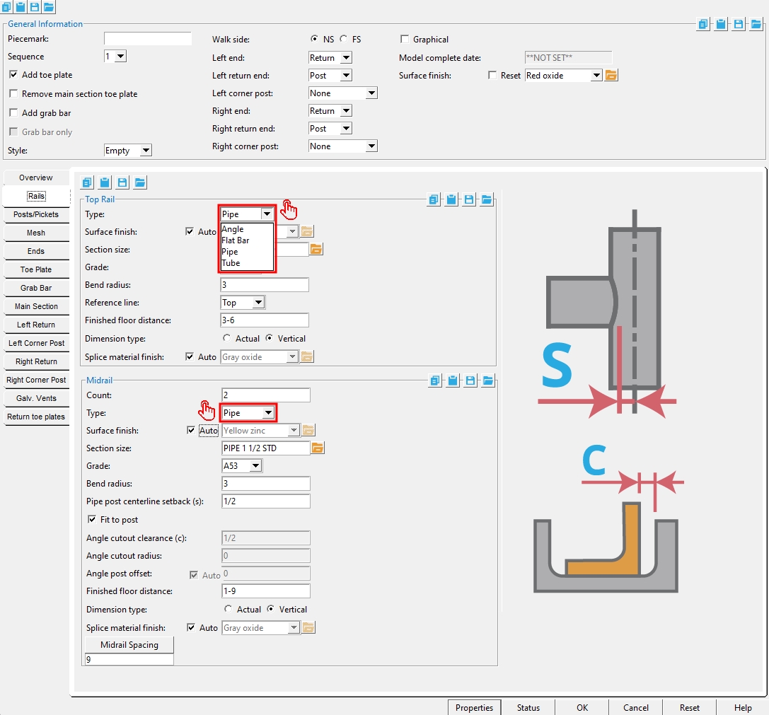
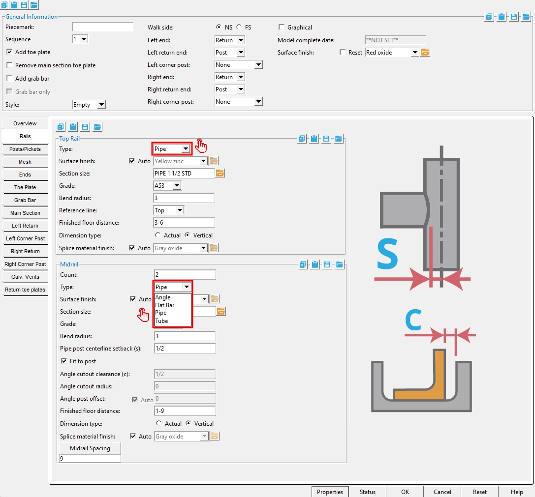
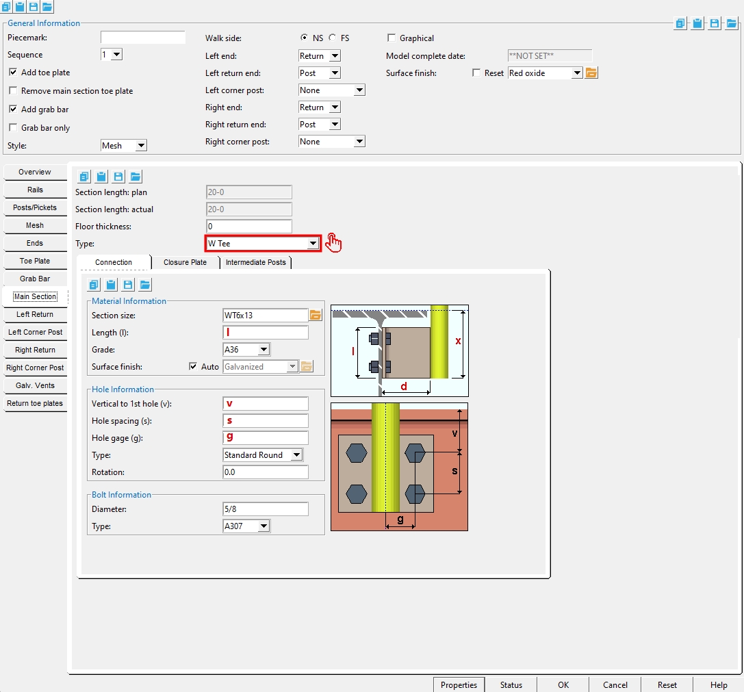
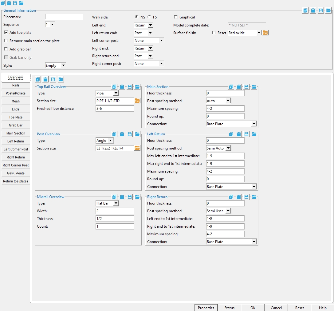
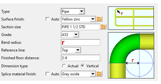
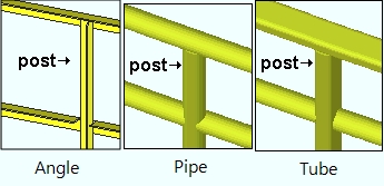
Type: Angle or Flat Bar or Pipe or Tube . This also sets the top rail " Type " under the " Rails " tab. The heel of an ' Angle ' top rail aligns with the workline. ' Flat Bar ', ' Pipe ' and ' Tube ' top rails are centered on the workline.
Section size: Any section size of the specified material type that is in the local shape file . You can type in the section size that you want, or you can press the "file cabinet" browse button ( ![]() ) and double-click any section that is on the list of available materials in the local shape file. Validation only lets you enter a material that is listed in the local shape file. Also, if you enter a section size that is not available, validation brings up a yes-no dialog with the warning, " The section size is not available from suppliers. Are you sure you want to use it? "
) and double-click any section that is on the list of available materials in the local shape file. Validation only lets you enter a material that is listed in the local shape file. Also, if you enter a section size that is not available, validation brings up a yes-no dialog with the warning, " The section size is not available from suppliers. Are you sure you want to use it? "
Material Type Typing in a size Material Window angle naming convention " Section size " HSS round (pipe) naming conventions " Section size " HSS rectangular (tube) naming conventions " Section size " round bar naming conventions " Section size " W tee naming convention " Section size " Also see : Click here for information on the handrail parts that these material types are used for. Setup:Hand Rail Setup ( Home > Project Settings > Job > Plugin Defaults ...)
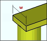
Width: The width of the top rail or midrail when its " Type " is ' Flat Bar '.
Thickness: The thickness of the top rail or midrail when its " Type " is ' Flat Bar '.
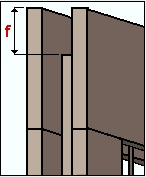
Finished floor distance: The actual or vertical distance that the member line (" Reference line ") is above the " Floor thickness ."
solids form
stick form
Midrail Count: The number of midrails.
Main Section/Left Return/Right Return
Floor thickness: The actual distance that the finished floor is above the work points established when the hand rail was added .
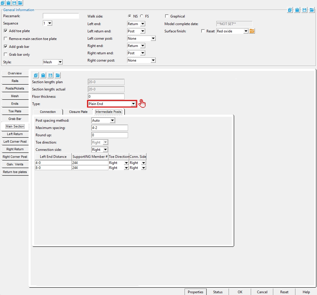
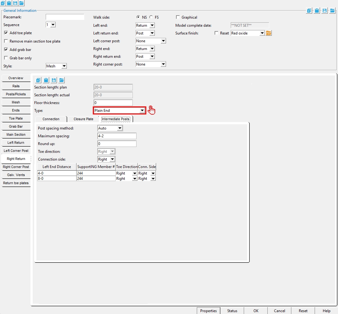
Post Spacing Method: Auto or Semi Auto or User or Semi User . Spacing between pipe and tube posts is measured center to center. Spacing between pipe posts is measured heel to heel.
Auto: instructs the Hand Rail program to first calculate the minimum number of posts that can be spaced less than the " Maximum spacing " apart from one another. Hand Rail then determines the number of spaces between posts. Hand Rail then divides the total distance between the end posts by the number of spaces to determine the spacing between posts.
Maximum Spacing: A maximum distance applied to the spacing between all of the posts in the main section, including the end posts.
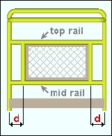
Round Up: If a value other than zero is entered here, the Hand Rail program rounds up the " Left End Distance " to the next increment of the round up value.
Semi Auto: lets you enter a " Left end to 1st intermediate " and a " Right end to 1st intermediate " distance to set the exact spacing from the outside (end) posts to the intermediate posts nearest to them. The Hand Rail program then uses the " Maximum spacing " to determine the spacing between any posts that are between these outside posts.
Max left end to 1st intermediate: A maximum distance to set the exact spacing from the outside (end) posts to the first intermediate post from the left end.
Max right end to 1st intermediate: A maximum distance to set the exact spacing from the outside (end) posts to the first intermediate post from the right end.
Maximum Spacing: A maximum distance applied to the spacing between the intermediate posts only.
Round up:If a value other than zero is entered here, the Hand Rail program rounds up the " Left End Distance " to the next increment of the round up value.
User: lets you specify exactly in the model where you want the intermediate posts located.
Post count: The total number of intermediate posts that you want between the two end posts.
Locate : Hand Rail add window closes and provides you Locate- Pan -Return mouse bindings for locating points on the workline of the handrail where you want the posts.
Left end to 1st intermediate: A distance to set the exact spacing from the outside (end) posts to the first intermediate post from the left end.
Right end to 1st intermediate: A distance to set the exact spacing from the outside (end) posts to the first intermediate post from the right end.
Maximum spacing: A maximum distance applied to the spacing between the intermediate posts only.
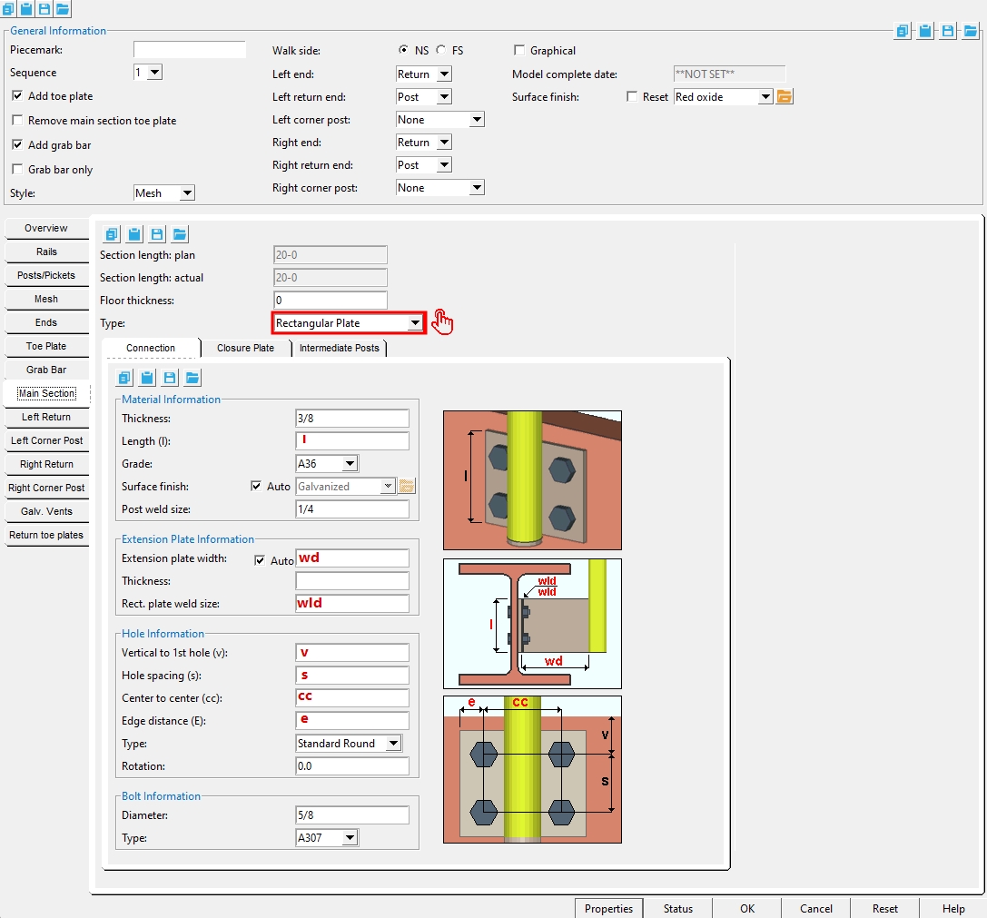
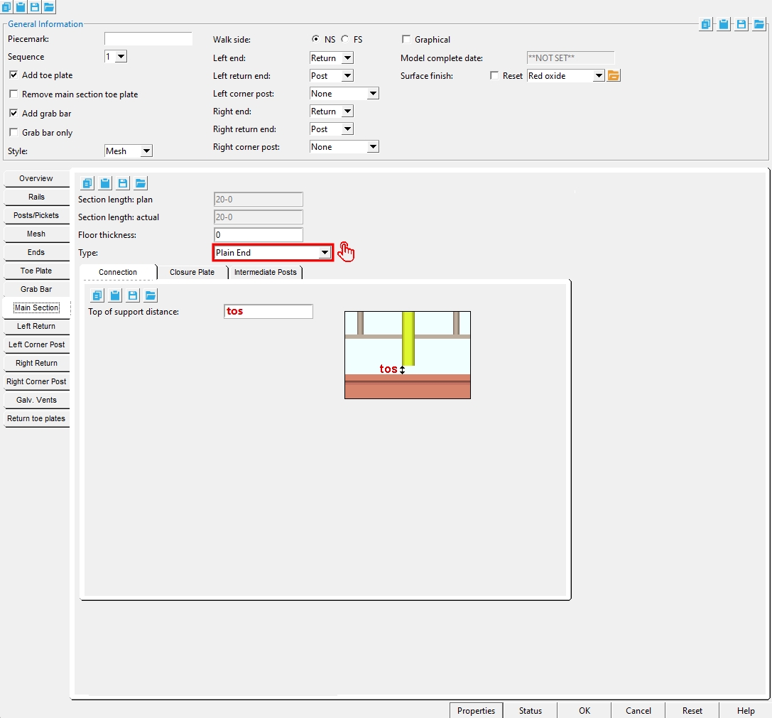
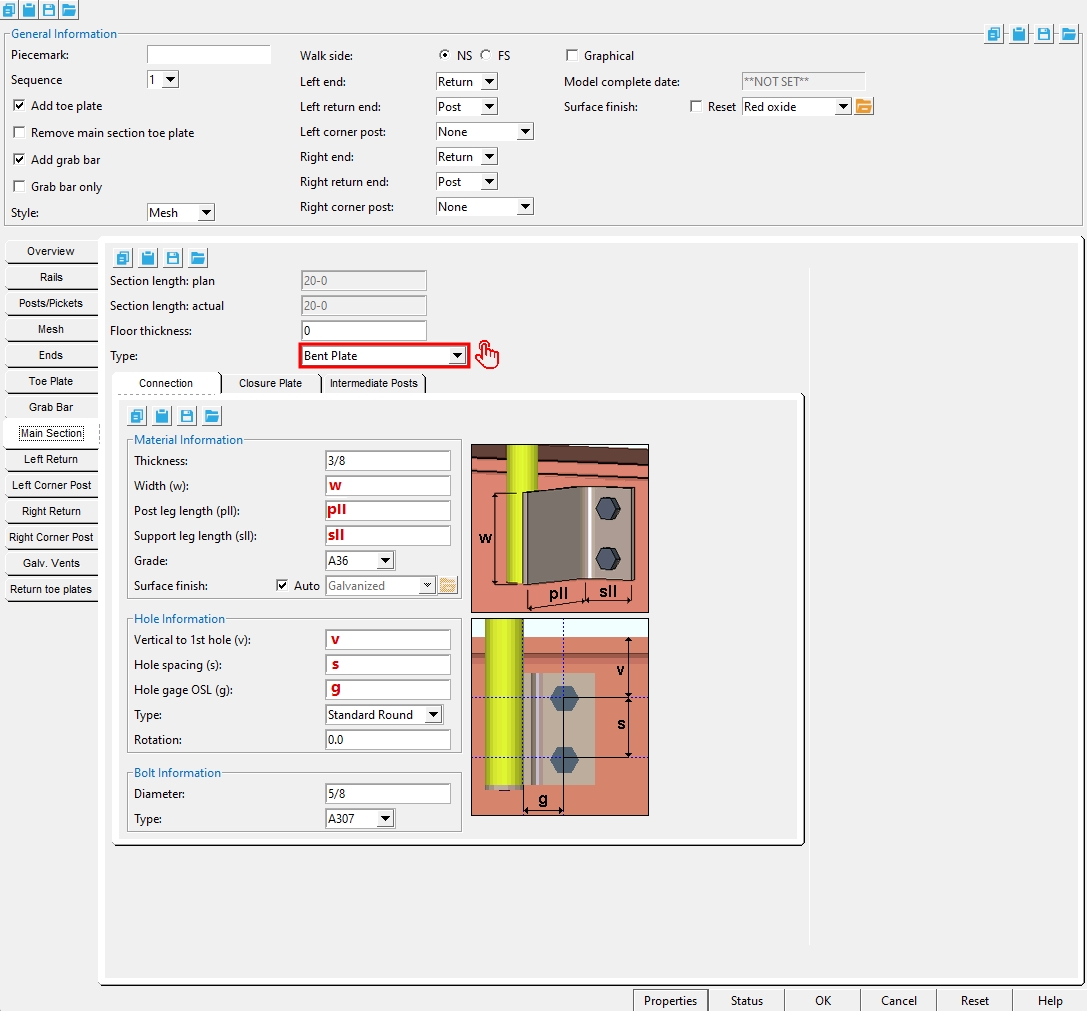
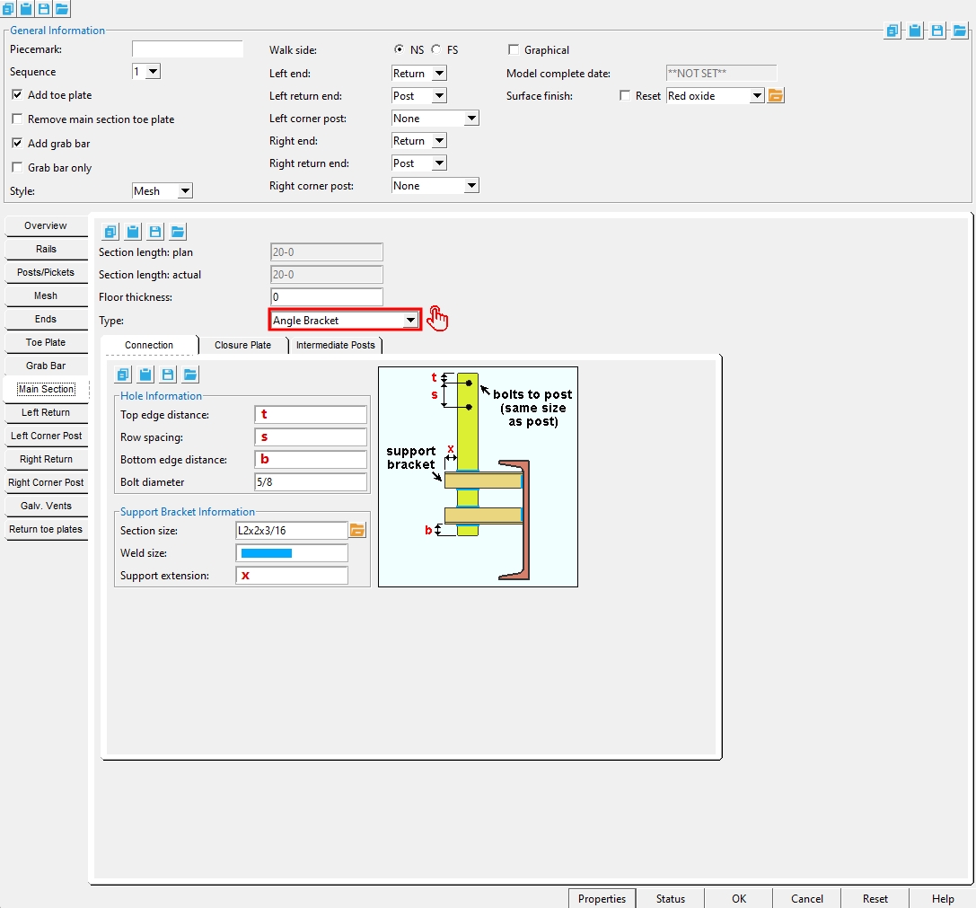
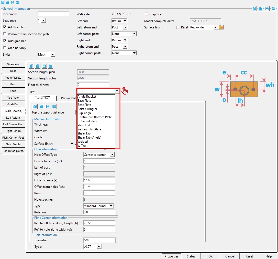
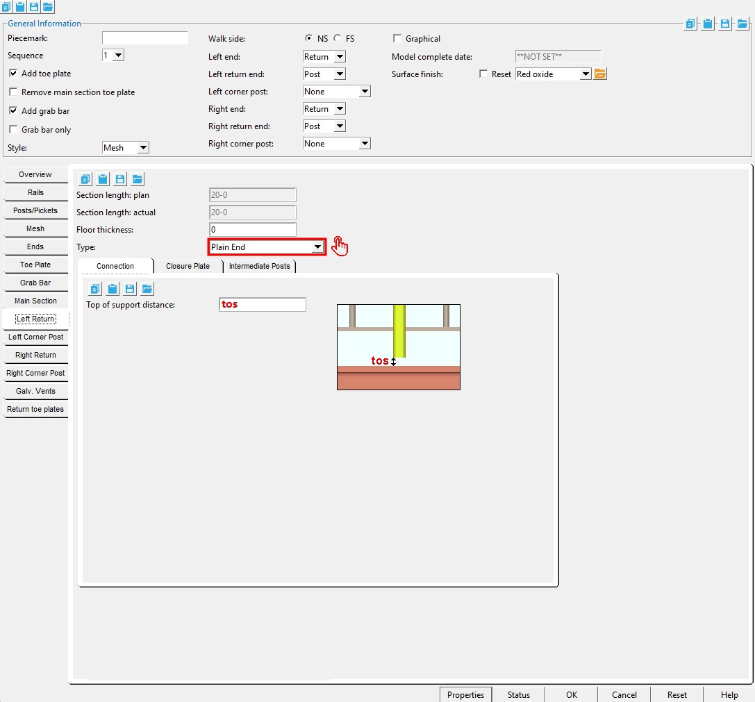
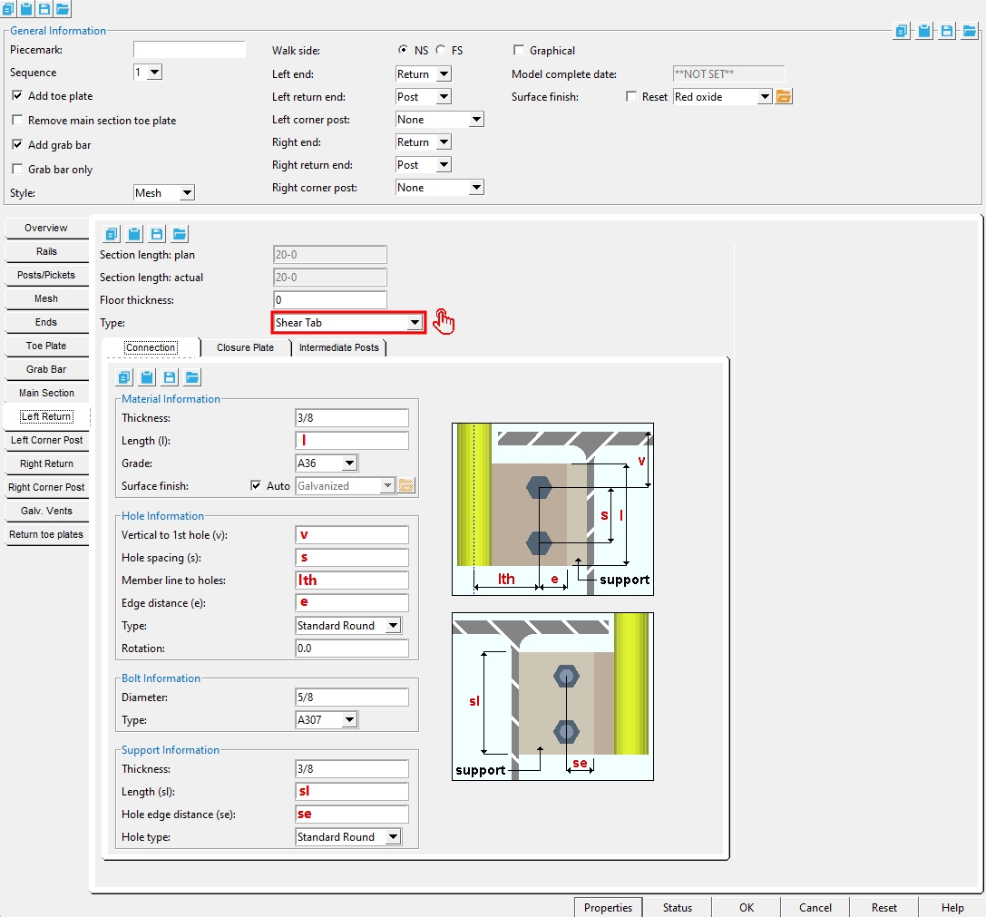
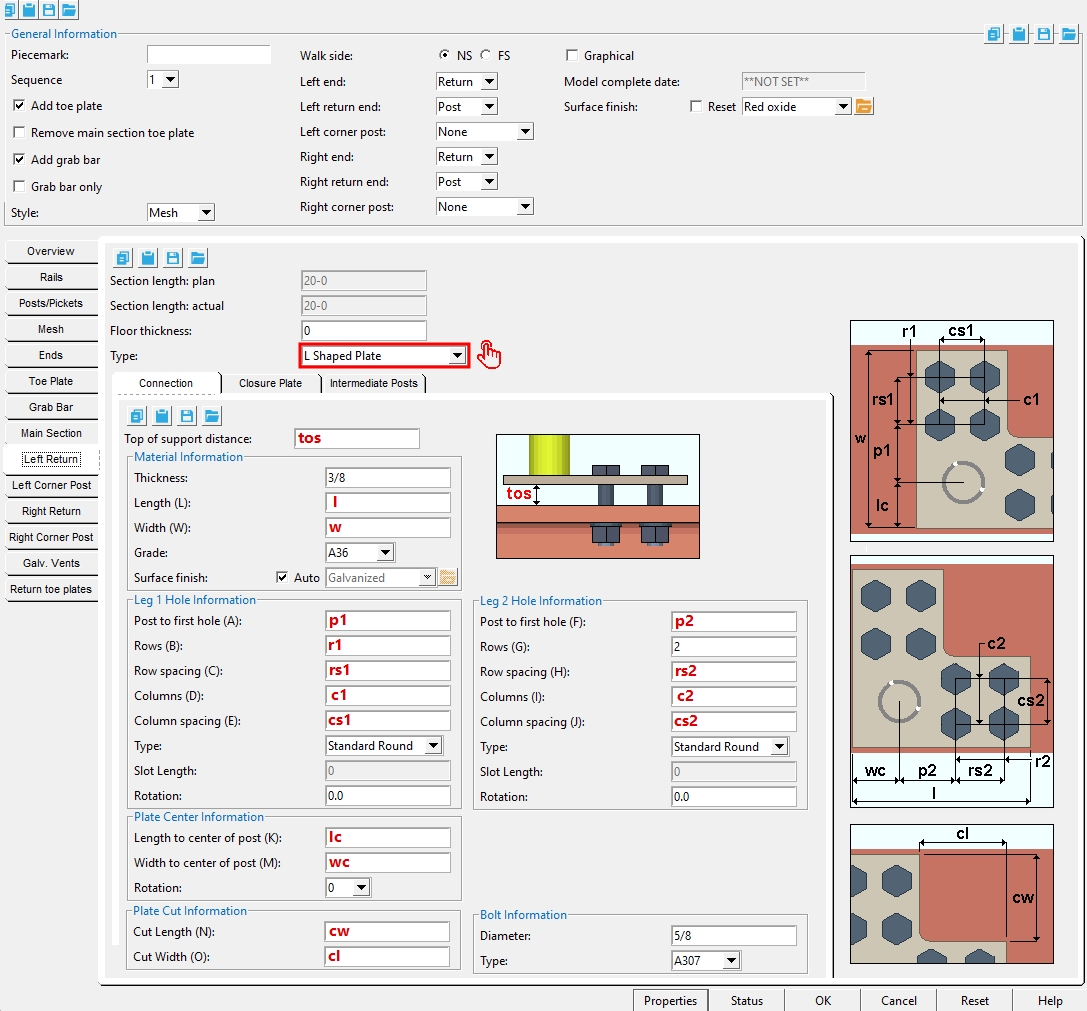
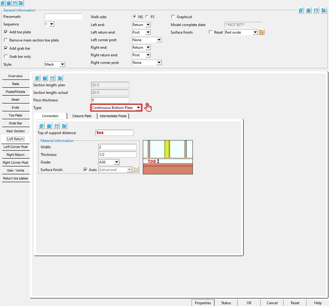
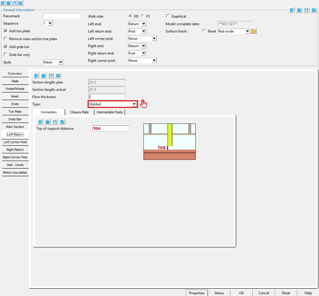
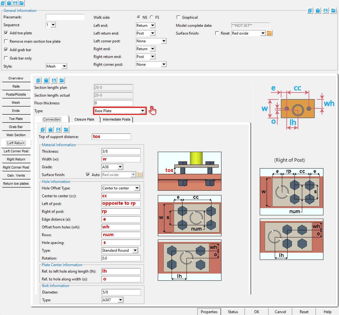
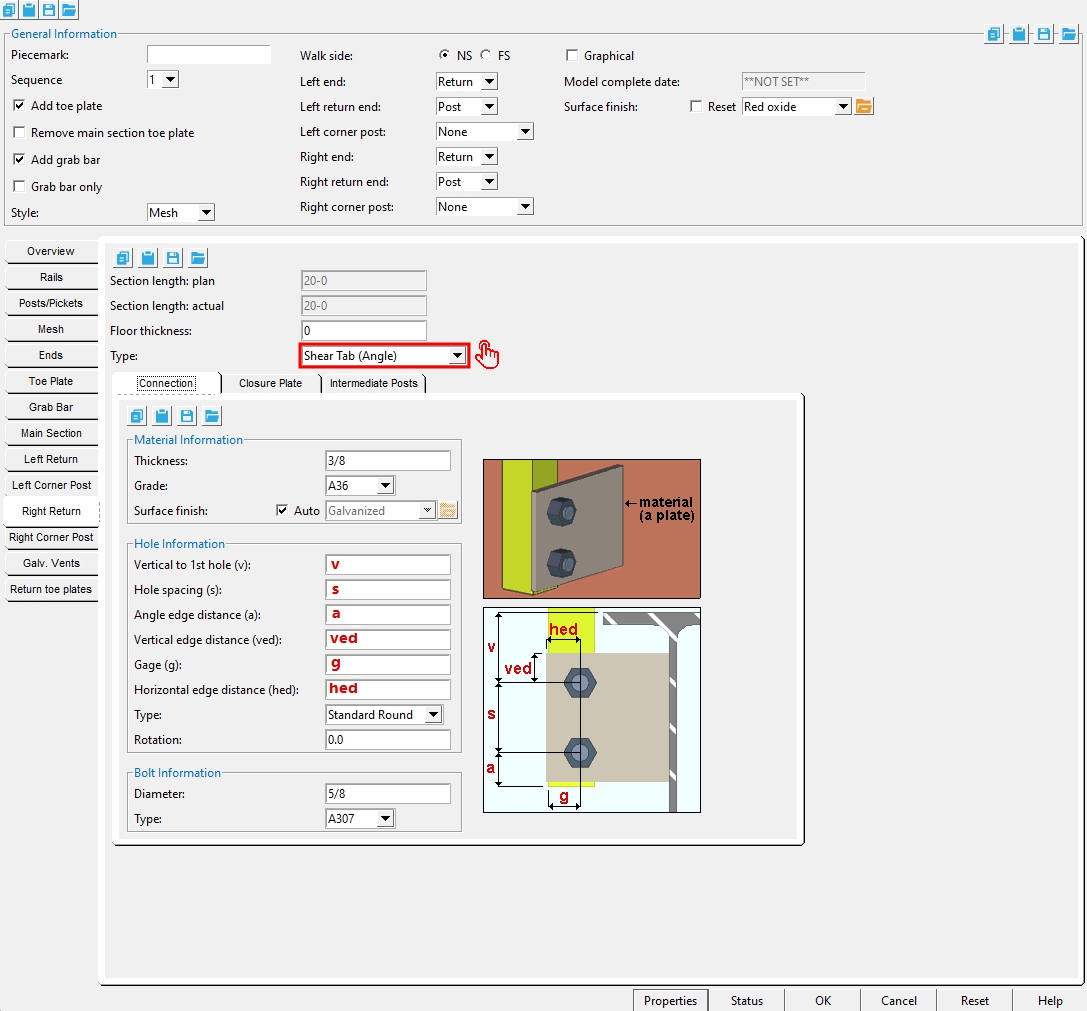
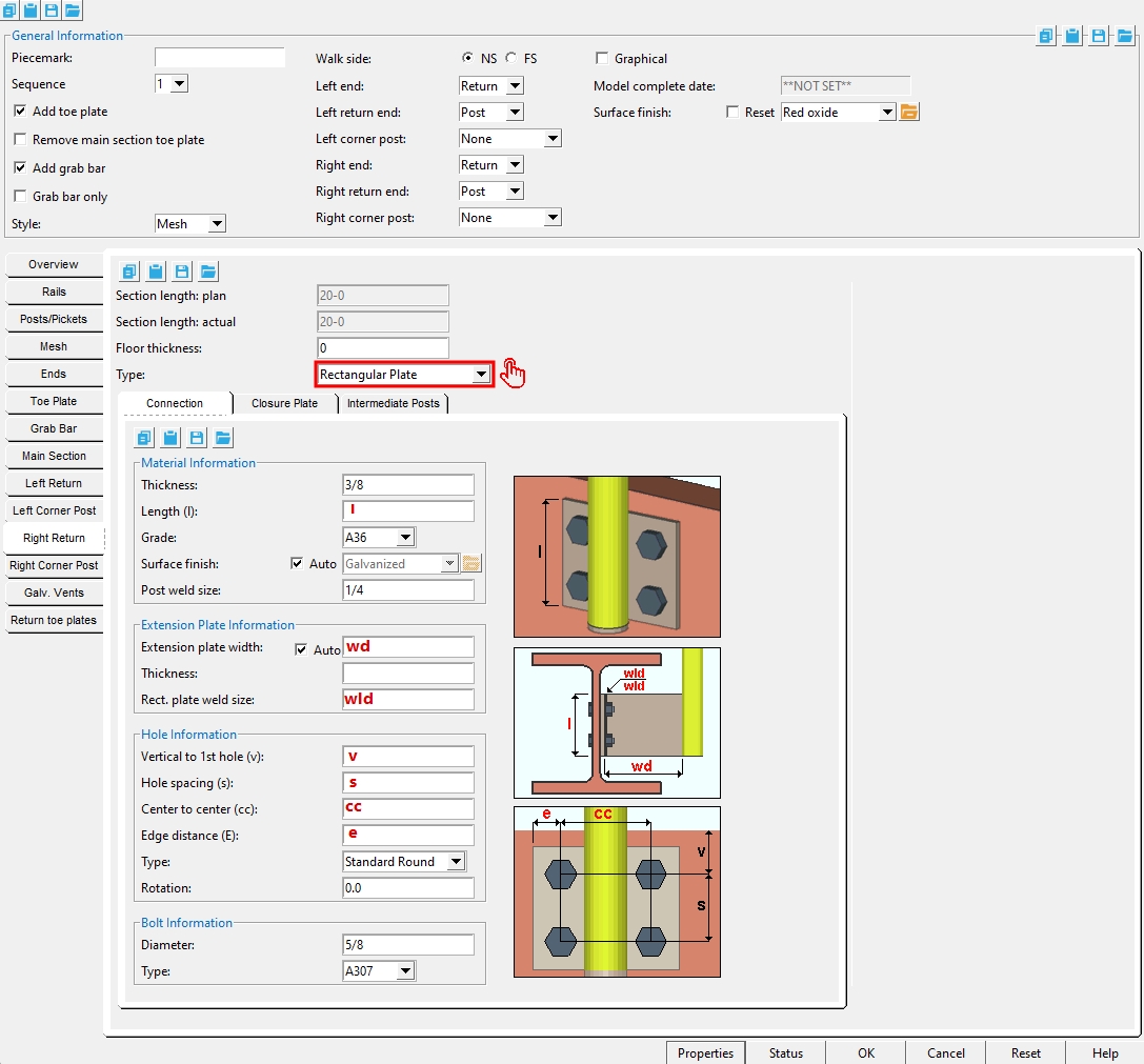
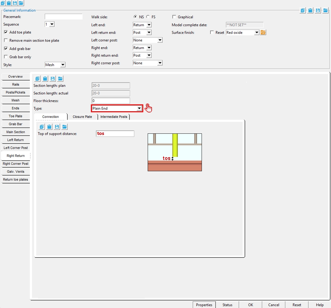
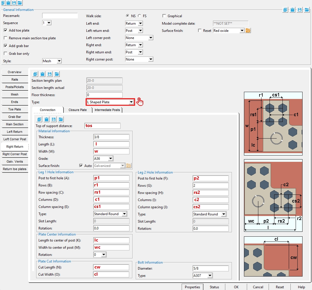
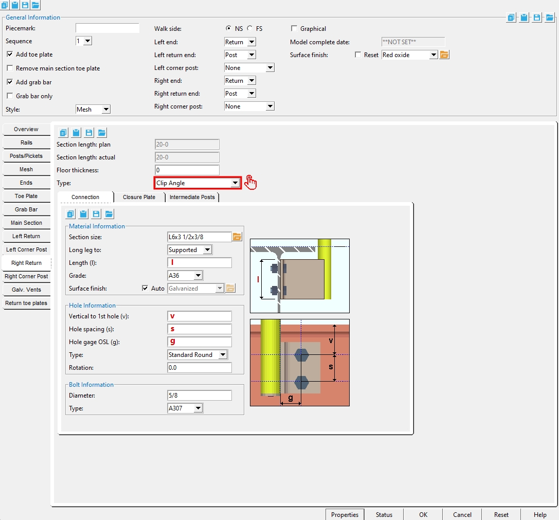
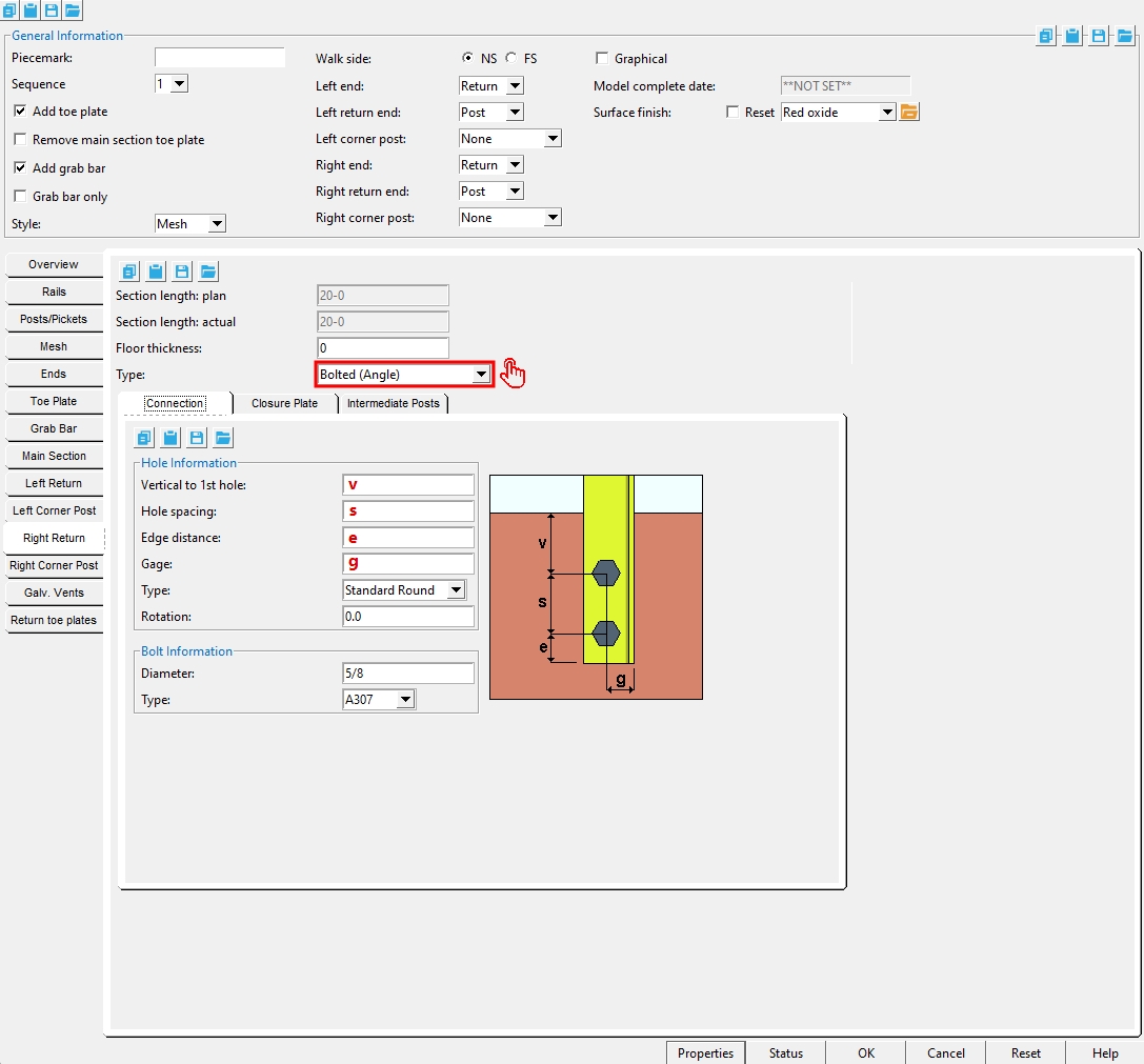
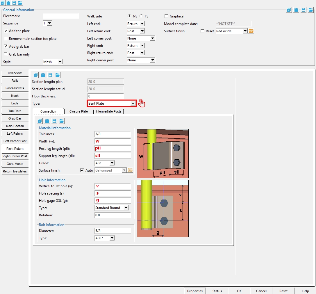
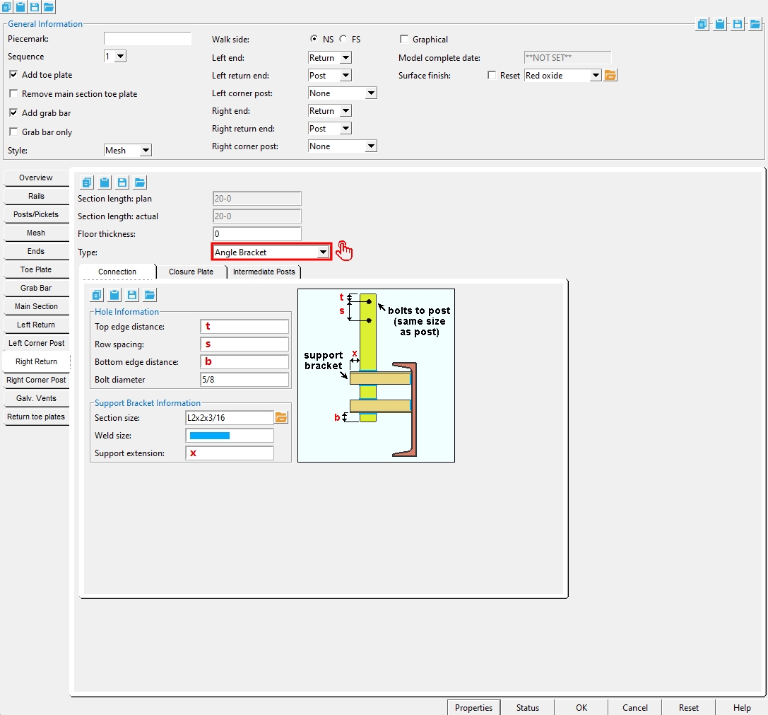
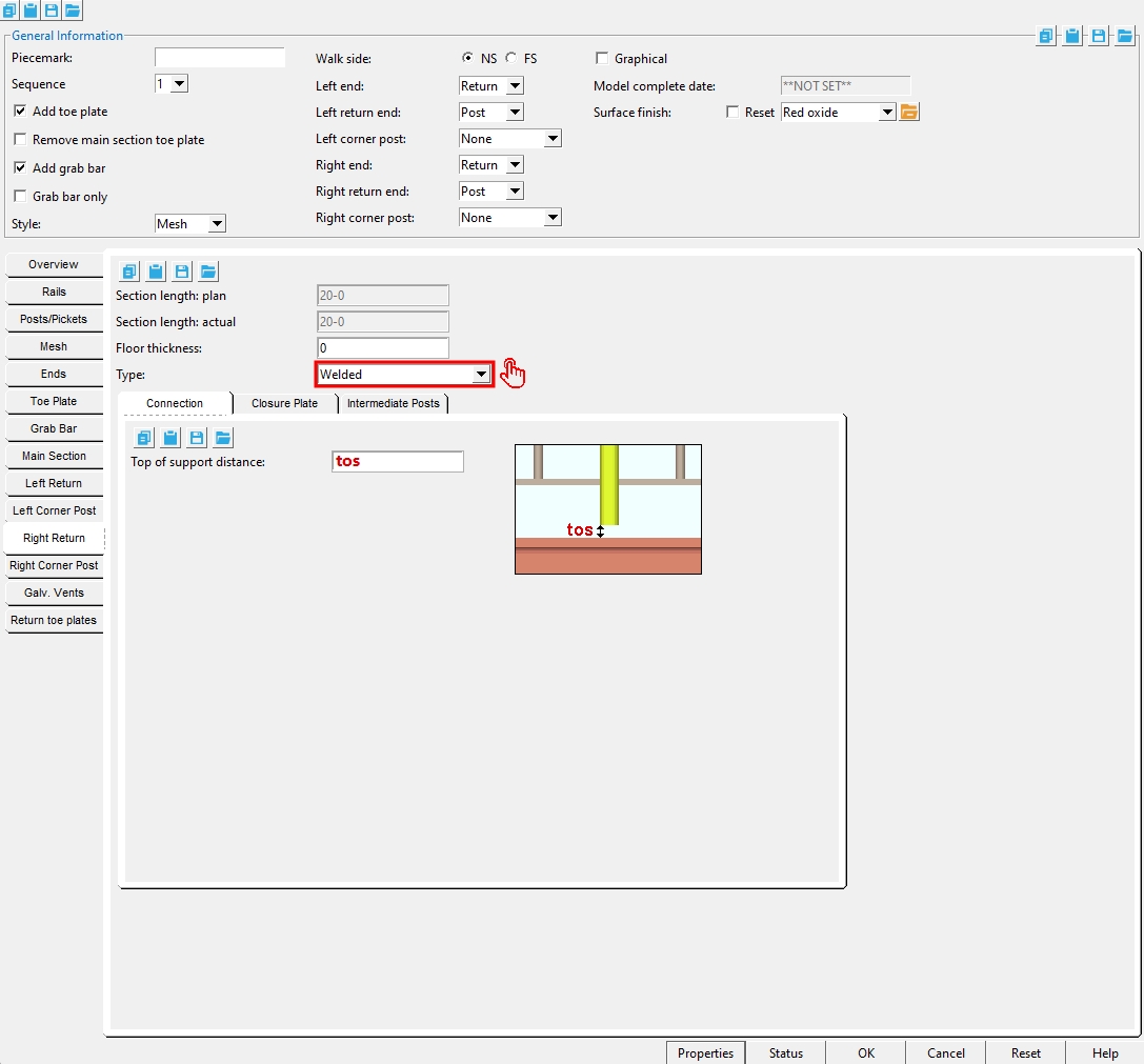
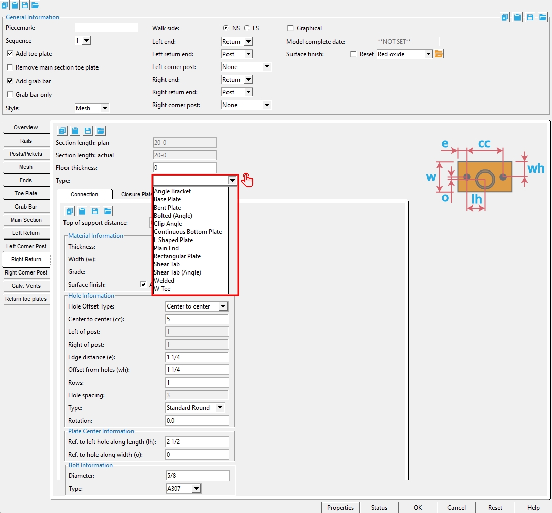
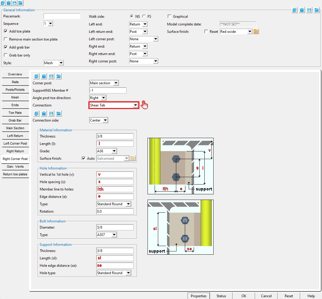
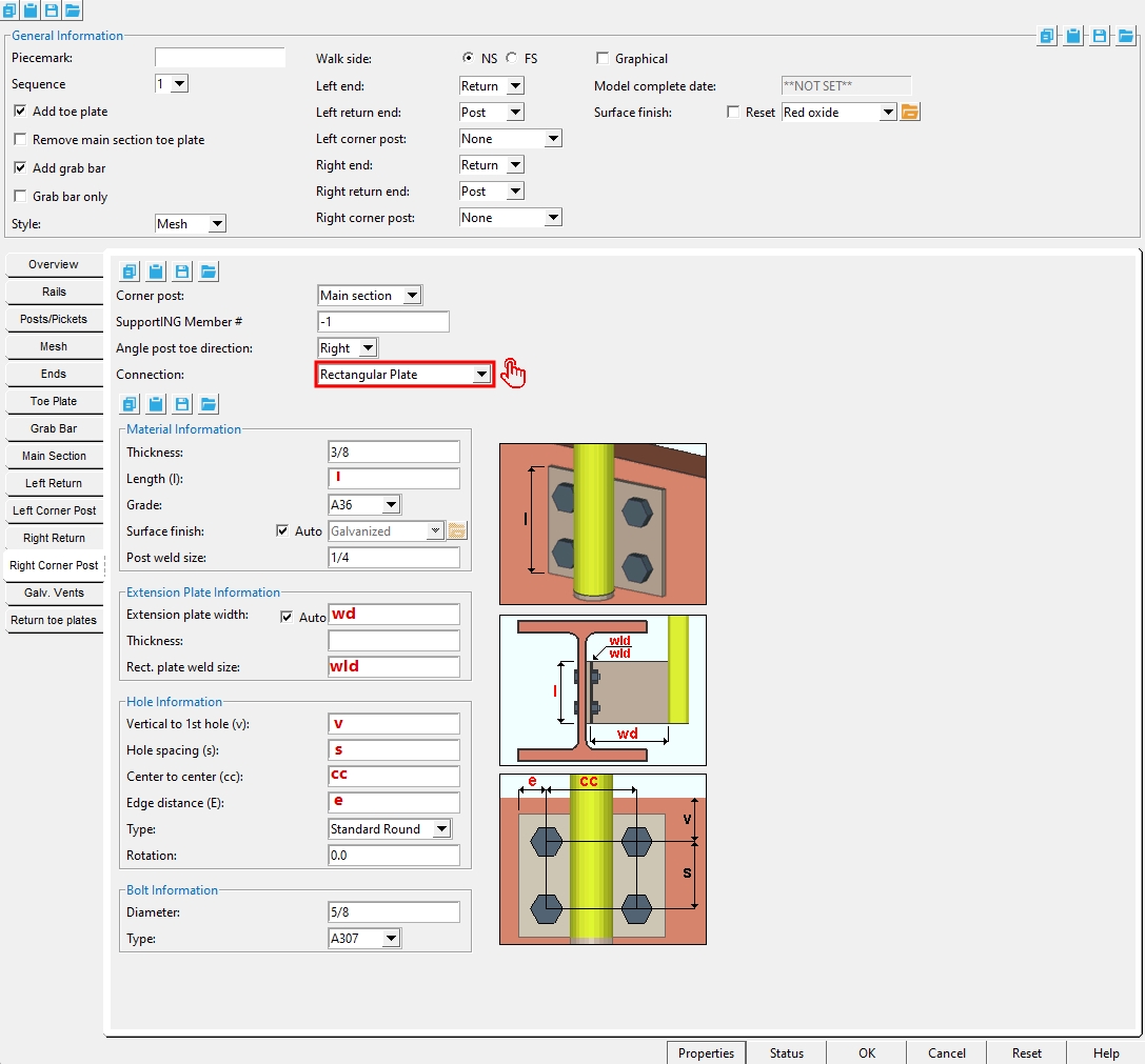
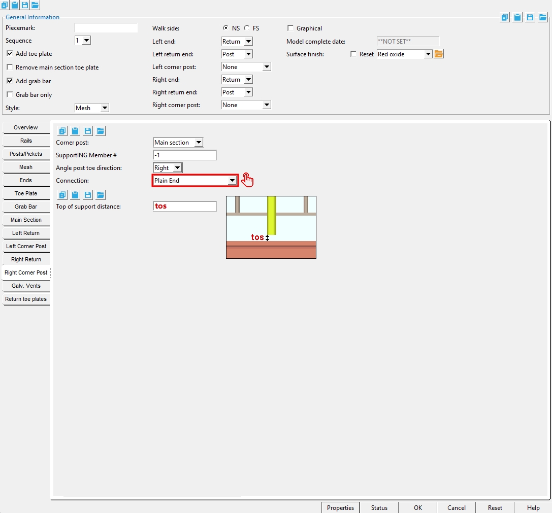
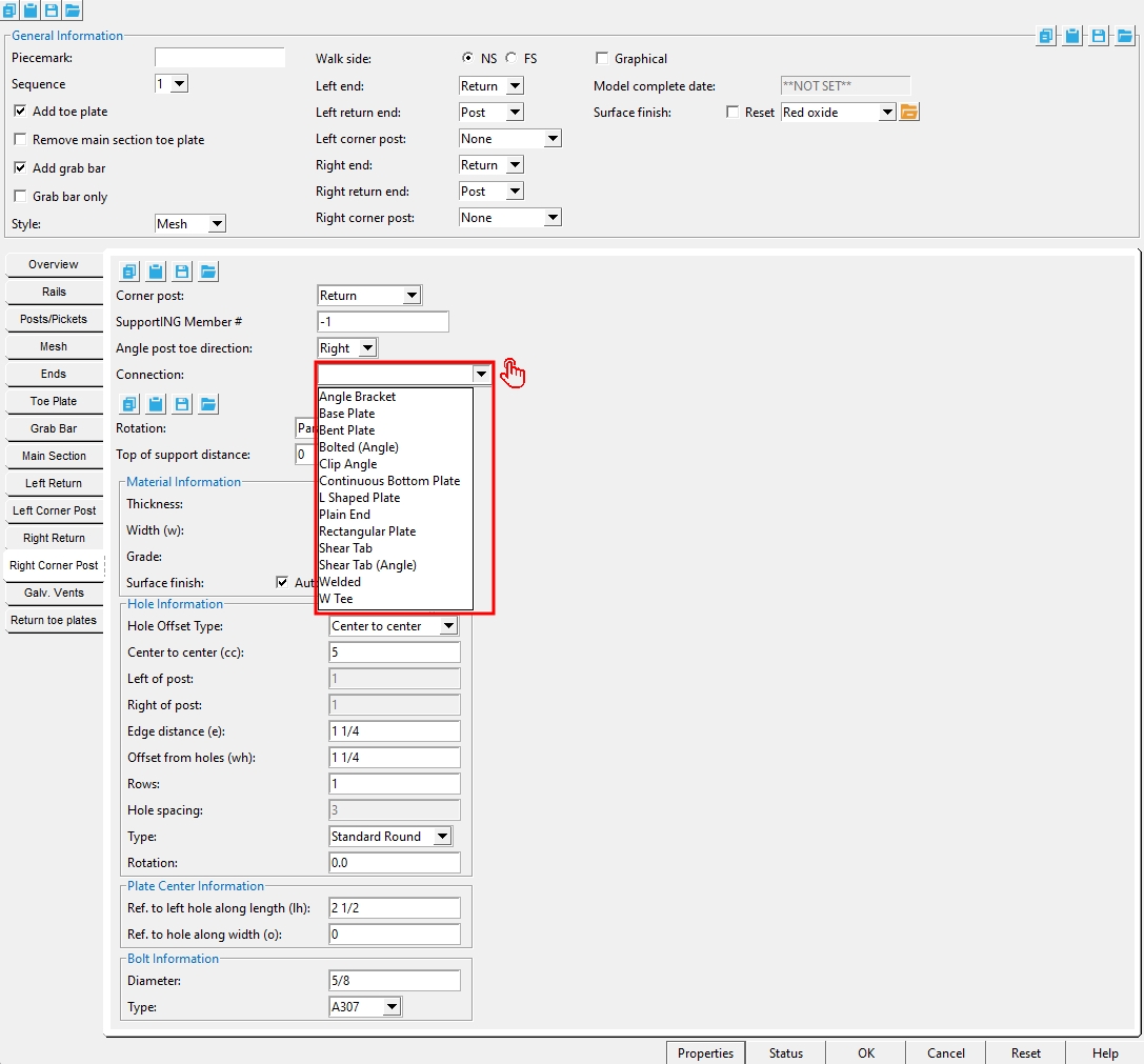
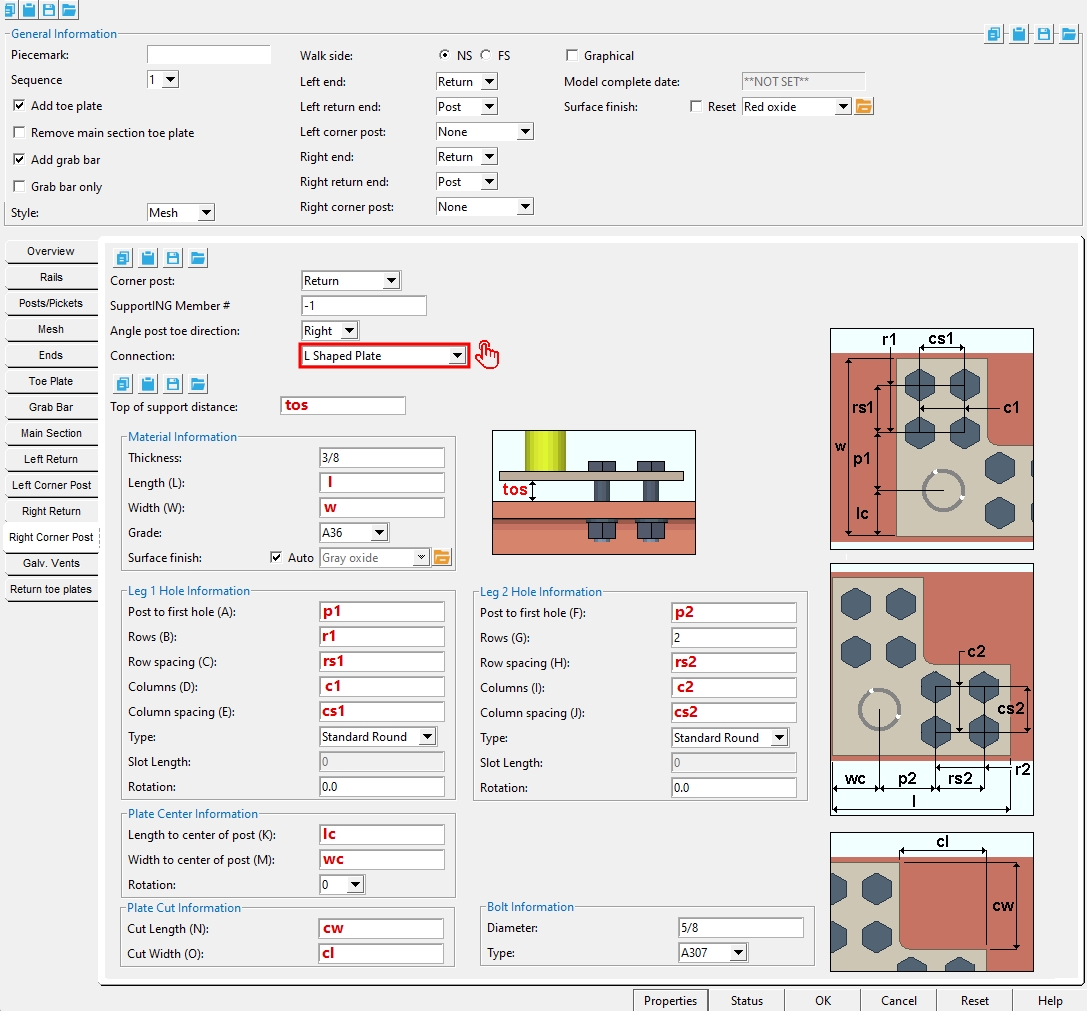
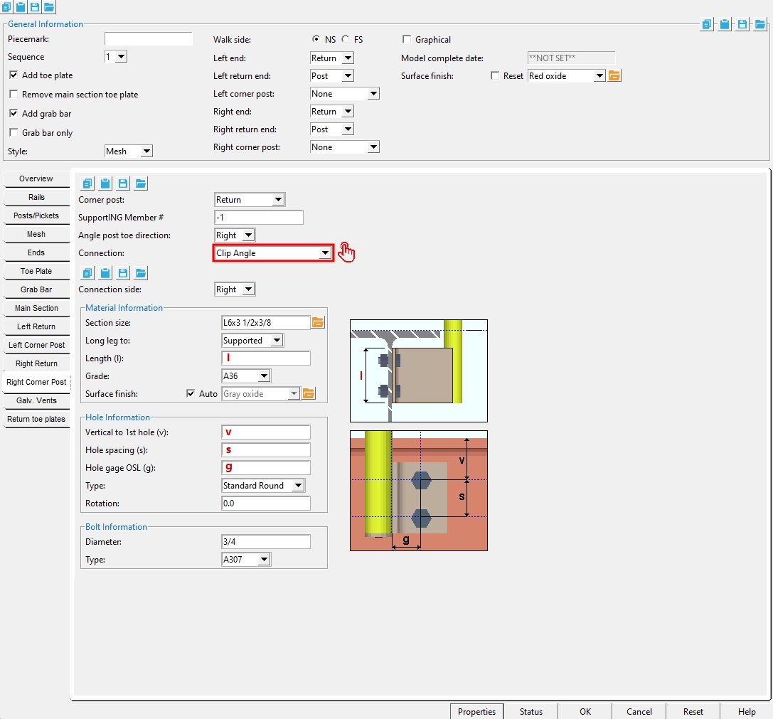
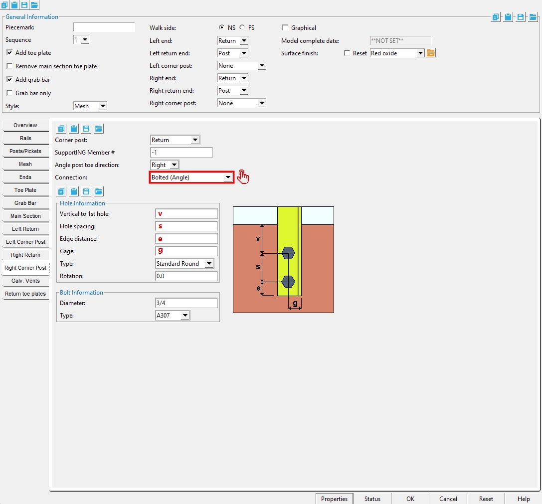
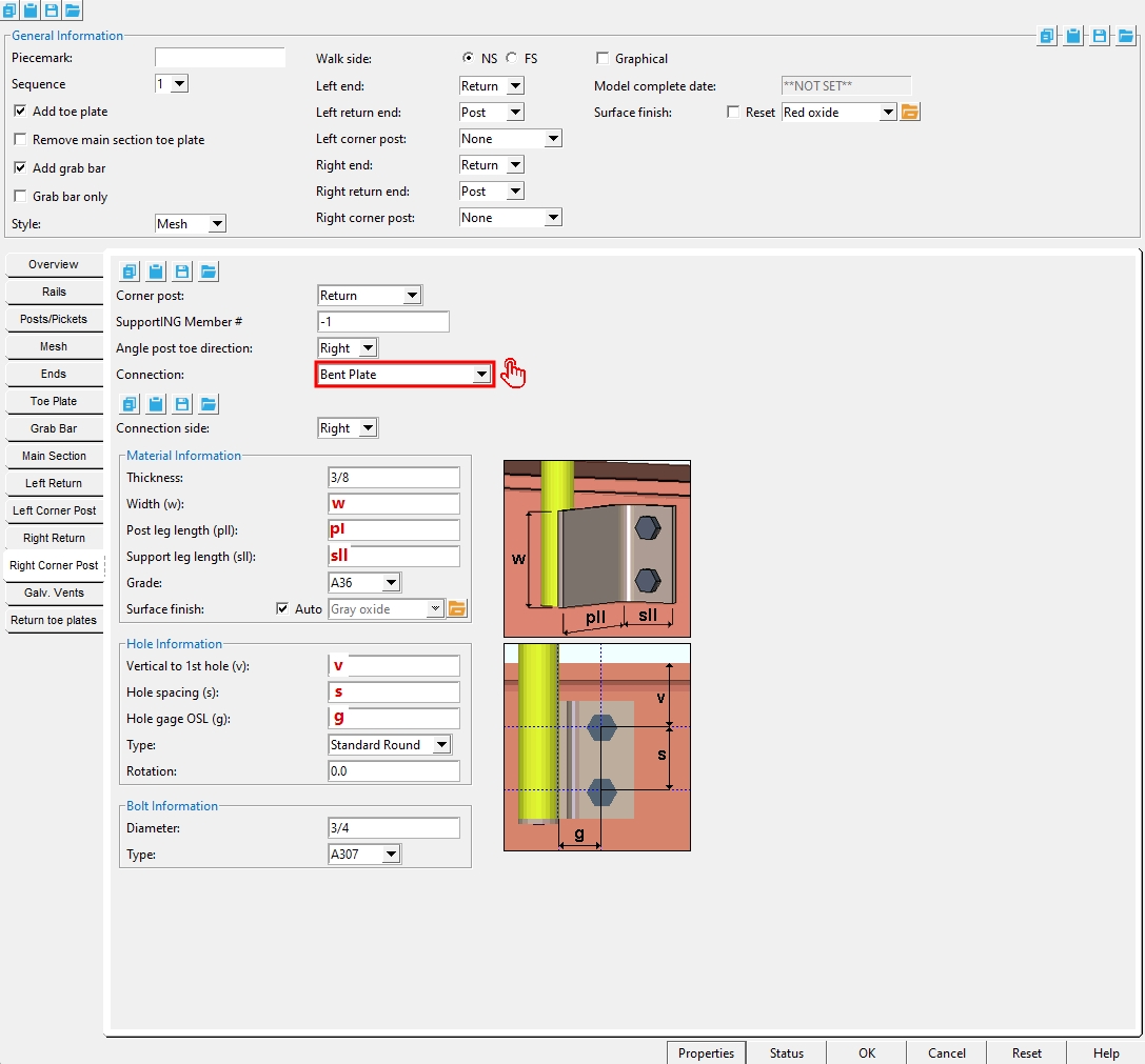
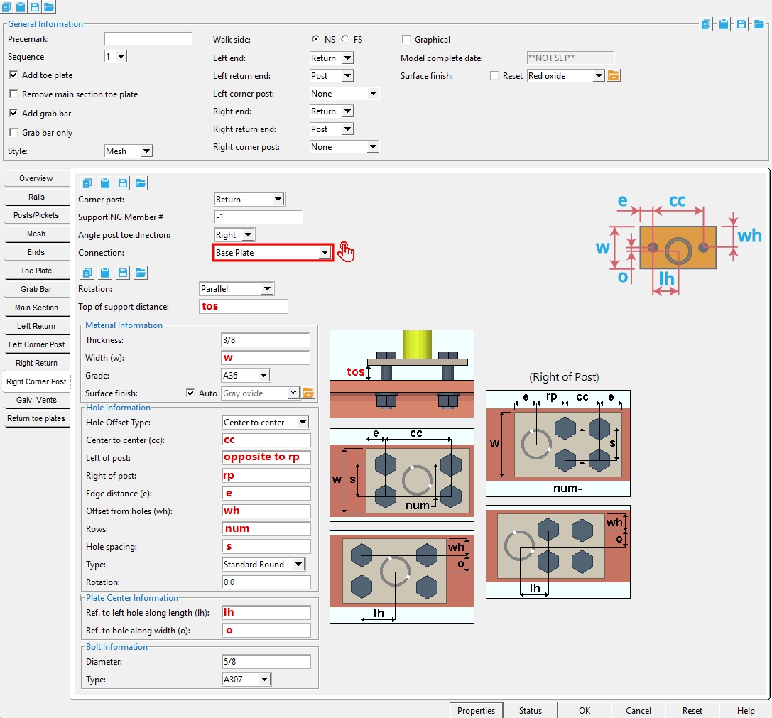
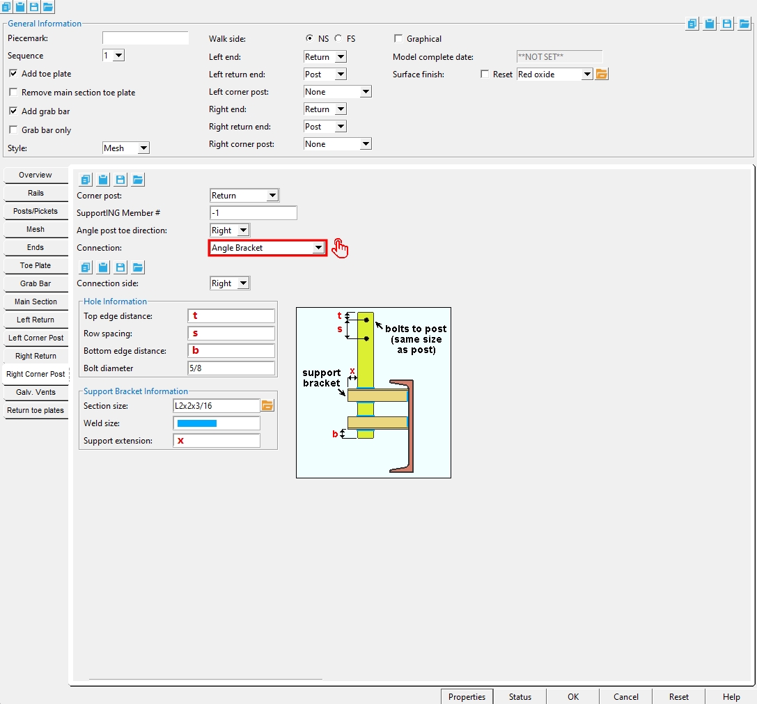
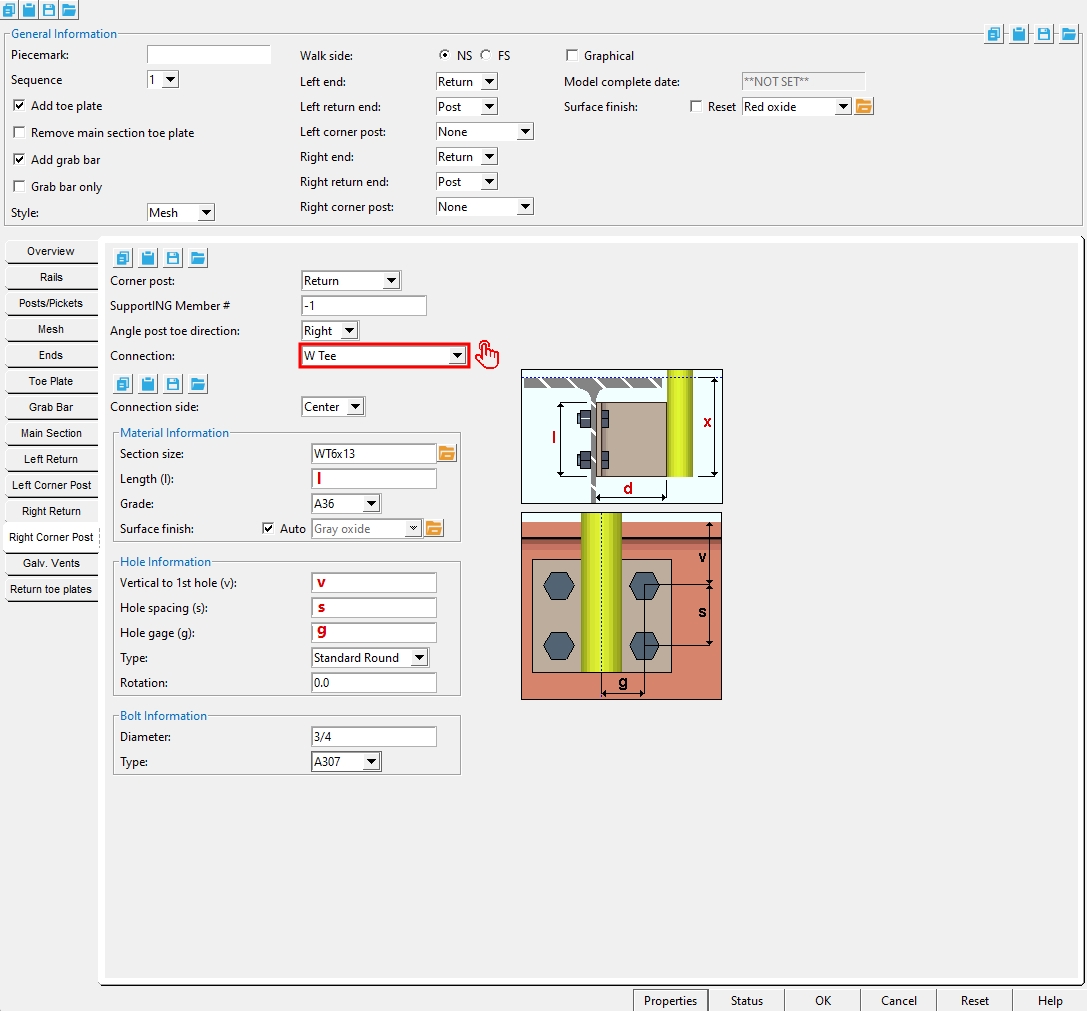
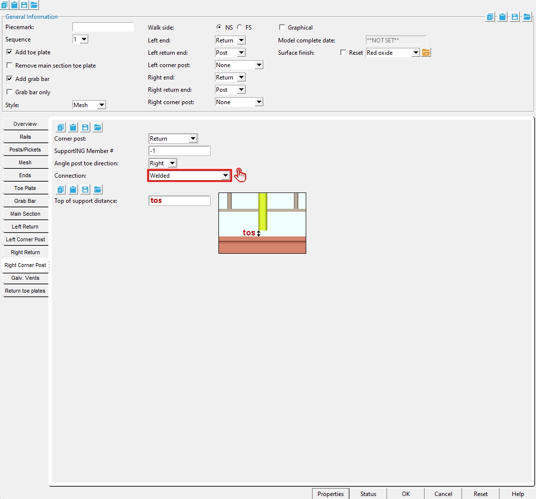
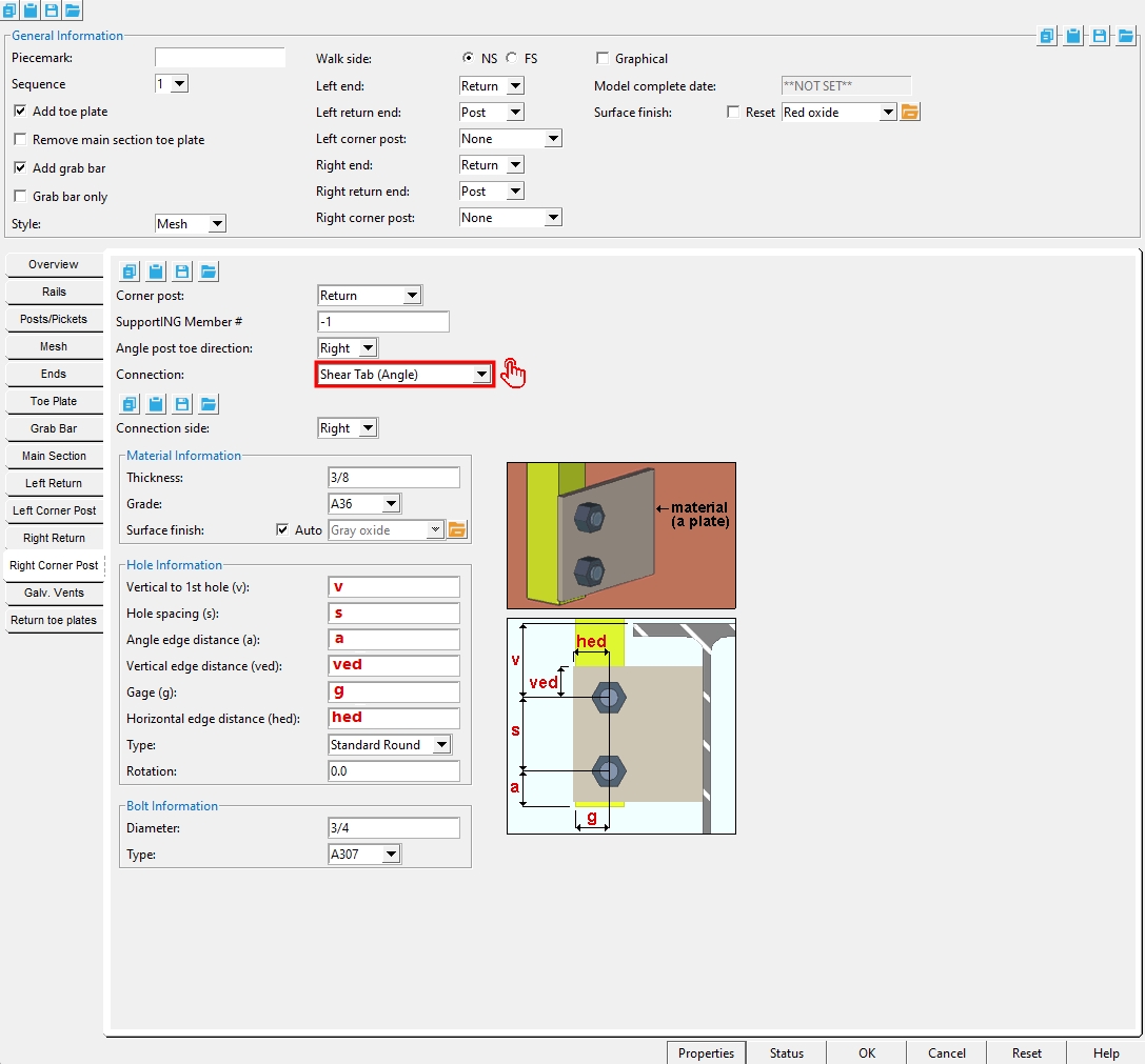
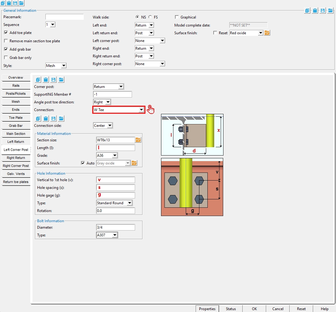
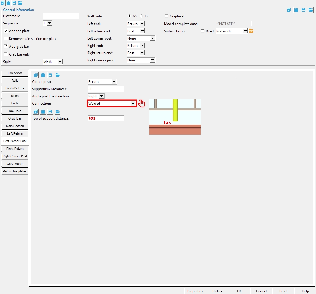
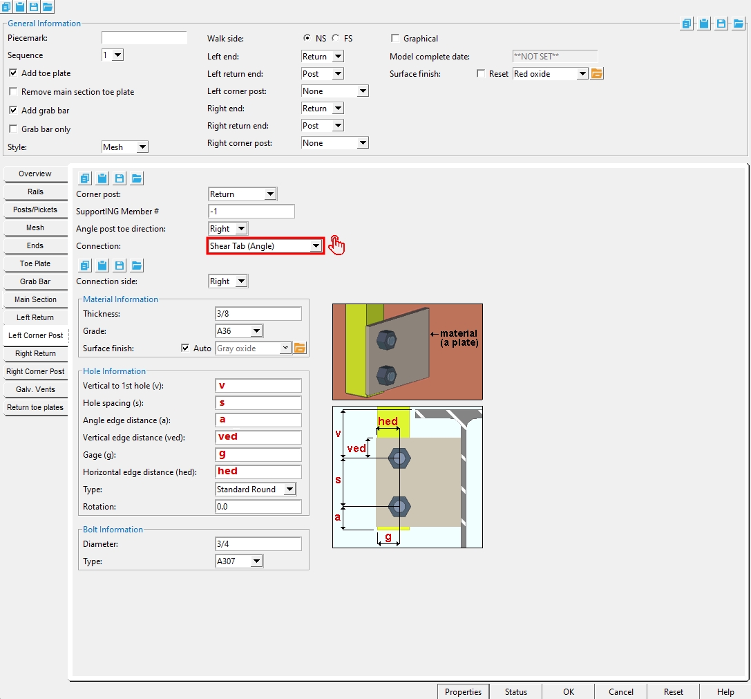
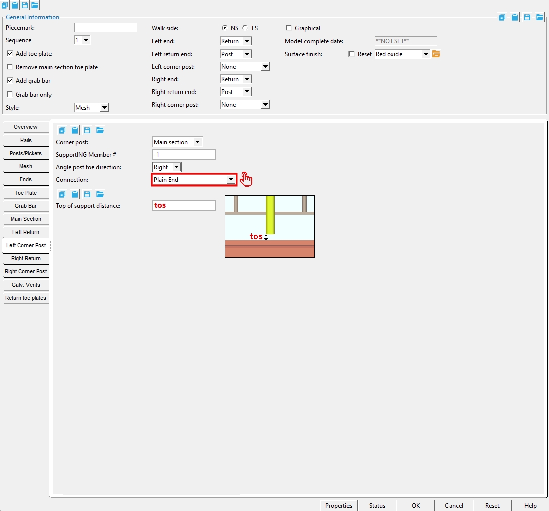
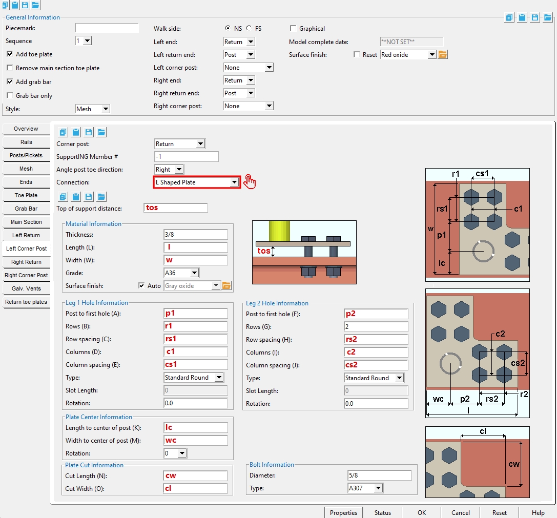
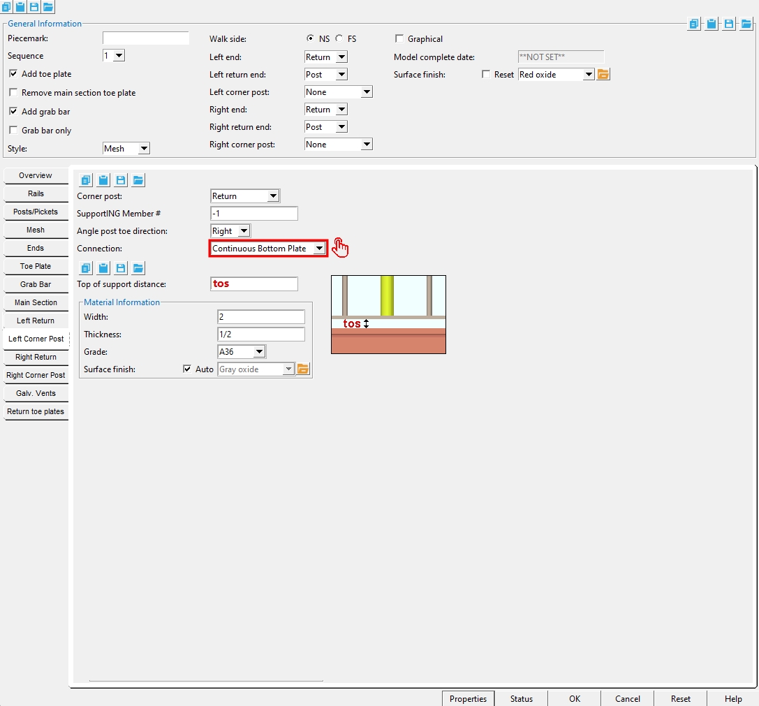
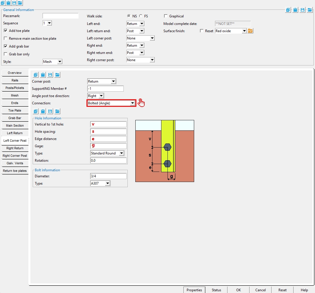
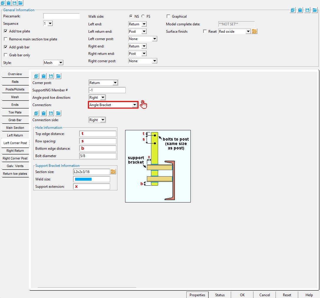
Connection: ' Angle Bracket ' or ' Base Plate ' or ' Bent Plate ' or ' Bolted (Angle) ' or ' Clip angle ' or ' Continuous Bottom Plate ' or ' L Shaped Plate ' or ' Plain End ' (see ' Welded ') or ' Rectangular Plate ' or ' Shear Tab ' or ' Shear Tab (Angle) ' or ' Welded ' or ' W Tee '.
Rails Tab
Top Rail
Type: Angle or Flat Bar or Pipe or Tube . This also sets the top rail " Type " under the " Overview " tab. The heel of an ' Angle ' top rail aligns with the workline. ' Flat Bar ', ' Pipe ' and ' Tube ' top rails are centered on the workline.
Surface finish: None or Sandblasted or Red oxide or Yellow zinc or Gray oxide or Blued steel or Galvanized or Duplex Coating or Undefined 1 or Undefined 2 or Undefined 3 or Red oxide 2 or Any user added surface finish. This affects the colors of Solid members on erection views in the Drawing Editor . This also sets the color when Output material color is set to Surface finish for a VRML Export or a DWG/DXF Export. The Color (not Surface finish) sets the color of this material in Modeling .
| sand blasted | red oxide | yellow zinc | user surface finish 1 |
| gray oxide | blued steel | galvanized | user surface finish 2 |
To assign a different surface finish, you can drop-down the current surface finish and select the one you want, or you can press the
Auto ![]() or
or ![]()
If this box
If the box
Note 1: Submaterial piecemarks can be split apart by surface finish. All surface finishes that do not have the Break Marks Material checked on can be applied to any like material with out the material splitting. If the Break Marks Material is checked on then only like materials with that specific surface finish can have the same piecemark, and because the submaterial marks differ so would the member's piecemark.
Note 2: When exporting a KISS file using "model" as the Data source surface finish data on the materials are compiled into the KISS download as follows, with a few exceptions (G=galvanized, N= none or sandblasted, P= others). Those exceptions are:
If the box for Finish routing in KISS export setup is set to a user routing
If the user has adjusted the Abbreviation for any of the default provided surface finishes
If you are using a user added surface finish
In these cases you will get what is provided in either the User routing, or the abbreviation field. For other exports it will always provide the abbreviation in the 'surface finishes' settings page.
Tip 1: Surface area is reported on the General Information window -- and this can be used to estimate the amount of coating required and its cost.
Tip 2: Changing Steel grade, Color, and Surface finish do not cause the plate to be regenerated. This means that, if you change those settings only, material fit operations such as a Fit Exact may optionally be preserved.
Report Writer: MemberMaterial.Material.SurfaceFinish
Setup: Surface Finish Settings
Pipe Top Rail
Section Size: Any section size of the pipe or tube support that is in the local shape file . You can type in the section size that you want, or you can press the "file cabinet" browse button ( ![]() ) and double-click any section that is on the list of available materials in the local shape file. Validation only lets you enter a material that is listed in the local shape file.
) and double-click any section that is on the list of available materials in the local shape file. Validation only lets you enter a material that is listed in the local shape file.
Grade: A53 or A500B or etc. The steel grade of the material. Steel grades that are available for a particular material depend on the type of that material. If the grade of steel that you want is not shown as a menu option ( ![]() ) on the Hand Rail window, you can add the grade you want to the setup table.
) on the Hand Rail window, you can add the grade you want to the setup table.
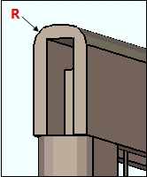
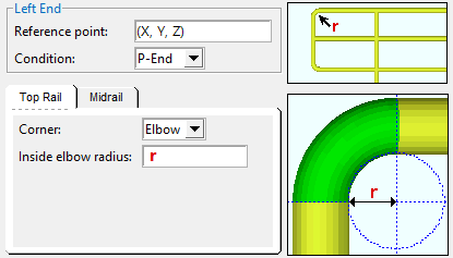
Bend radius: A distance that defines the inside radius of bending for the top corner of a P-end. This applies when the end " Condition " is ' P-End ' and the " Corner " is ' Elbow '. The distance entered here is exactly the same distance that is entered as the top rail's " Inside elbow radius " for each end that has a P-end.
Tube Top Rail
Section Size: Any section size of the pipe or tube support that is in the local shape file . You can type in the section size that you want, or you can press the "file cabinet" browse button ( ![]() ) and double-click any section that is on the list of available materials in the local shape file. Validation only lets you enter a material that is listed in the local shape file.
) and double-click any section that is on the list of available materials in the local shape file. Validation only lets you enter a material that is listed in the local shape file.
Long side direction: Horizontal or Vertical . This applies when the top rail " Type " is a ' Tube ' that has a " Section size " with one side longer than the other. This sets whether that long side is horizontal or vertical
Grade: A53 or A500B or etc. The steel grade of the material. Steel grades that are available for a particular material depend on the type of that material. If the grade of steel that you want is not shown as a menu option ( ![]() ) on the Hand Rail window, you can add the grade you want to the setup table.
) on the Hand Rail window, you can add the grade you want to the setup table.
Angle Top Rail
Section Size: Any section size of the pipe or tube support that is in the local shape file . You can type in the section size that you want, or you can press the "file cabinet" browse button ( ![]() ) and double-click any section that is on the list of available materials in the local shape file. Validation only lets you enter a material that is listed in the local shape file.
) and double-click any section that is on the list of available materials in the local shape file. Validation only lets you enter a material that is listed in the local shape file.
Long leg direction: Horizontal or Vertical .
|
Top rail:
|
' Vertical '
|
' Horizontal' |
|
|
|
| These views look down the " Reference line. " All angles are 3x2x1/4. The post's " Long leg direction " is set under the " Post/Pickets " tab. | ||
Grade: A36 or A572-50 or etc. The steel grade of the material. Steel grades that are available for a particular material depend on the type of that material. If the grade of steel that you want is not shown as a menu option ( ![]() ) on the Hand Rail window, you can add the grade you want to the setup table.
) on the Hand Rail window, you can add the grade you want to the setup table.
Flat Bar Top Rail
Width: The width of the top rail when its " Type " is ' Flat Bar '. You can enter this width in the primary dimension " Units " or other units .
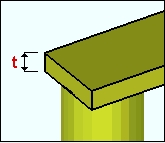
Thickness: The thickness of the top rail when its " Type " is ' Flat Bar '. You can enter this thickness in the primary dimension " Units " or other units .
Grade: A36 or A572-50 or etc. The steel grade of the material. Steel grades that are available for a particular material depend on the type of that material. If the grade of steel that you want is not shown as a menu option ( ![]() ) on the Hand Rail window, you can add the grade you want to the setup table.
) on the Hand Rail window, you can add the grade you want to the setup table.
Reference line: Top or Center or Bottom . The member line of the handrail that shows its location when the handrail is displayed in stick form . The choice you make here affects the placement of the top rail material. The " Finished floor distance " (below) sets the distance that this member line is from the
| solids form
|
stick form
|
' Top ' aligns the top of the top rail material with the member line.
' Center ' aligns the center of the top rail material with the member line.
' Bottom ' aligns the bottom of the top rial material with the member line.
Related: The " Finished floor distance " (immediately below) is measured to this line.
Finished floor distance: The actual or vertical distance that the member line (" Reference line ") is above the " Floor thickness ." In the example below, the construction line through the work point (wkpt) shows the top of steel work line established by the points that were located when the handrail was added.
| solids form
|
stick form
|
Dimension type: Actual or Vertical . For a sloping handrail, the ' Actual ' distance is different than the ' Vertical ' distance. If the handrail is not sloping, this distance is measured the same as the ' Actual ' distance since the vertical distance will be perpendicular to the floor and member line.
|
' Actual ' sets the " Finished floor distance " to be measured as the shortest distance (a perpendicular) between the member line and the floor. ' Vertical ' sets the " Finished floor distance " to be measured vertically between the member line and the floor. |
Splice Material Finish: Sets the splice connection material finish .
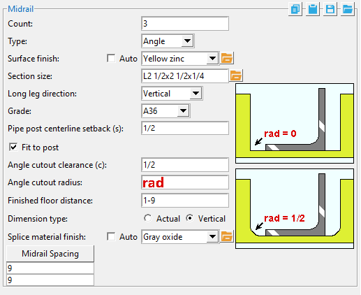
Midrail
Count: The number of midrails.
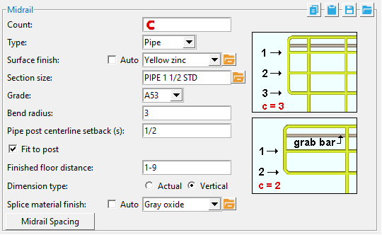
Type: Angle or Flat Bar or Pipe or Tube . This also sets the top rail " Type " under the " Overview " tab. The heel of an ' Angle ' top rail aligns with the workline. ' Flat Bar ', ' Pipe ' and ' Tube ' top rails are centered on the workline.
Surface finish: None or Sandblasted or Red oxide or Yellow zinc or Gray oxide or Blued steel or Galvanized or Duplex Coating or Undefined 1 or Undefined 2 or Undefined 3 or Red oxide 2 or Any user added surface finish. This affects the colors of Solid members on erection views in the Drawing Editor . This also sets the color when Output material color is set to Surface finish for a VRML Export or a DWG/DXF Export. The Color (not Surface finish) sets the color of this material in Modeling .
| sand blasted | red oxide | yellow zinc | user surface finish 1 |
| gray oxide | blued steel | galvanized | user surface finish 2 |
To assign a different surface finish, you can drop-down the current surface finish and select the one you want, or you can press the
Auto ![]() or
or ![]()
If this box
If the box
Note 1: Submaterial piecemarks can be split apart by surface finish. All surface finishes that do not have the Break Marks Material checked on can be applied to any like material with out the material splitting. If the Break Marks Material is checked on then only like materials with that specific surface finish can have the same piecemark, and because the submaterial marks differ so would the member's piecemark.
Note 2: When exporting a KISS file using "model" as the Data source surface finish data on the materials are compiled into the KISS download as follows, with a few exceptions (G=galvanized, N= none or sandblasted, P= others). Those exceptions are:
If the box for Finish routing in KISS export setup is set to a user routing
If the user has adjusted the Abbreviation for any of the default provided surface finishes
If you are using a user added surface finish
In these cases you will get what is provided in either the User routing, or the abbreviation field. For other exports it will always provide the abbreviation in the 'surface finishes' settings page.
Tip 1: Surface area is reported on the General Information window -- and this can be used to estimate the amount of coating required and its cost.
Tip 2: Changing Steel grade, Color, and Surface finish do not cause the plate to be regenerated. This means that, if you change those settings only, material fit operations such as a Fit Exact may optionally be preserved.
Report Writer: MemberMaterial.Material.SurfaceFinish
Setup: Surface Finish Settings
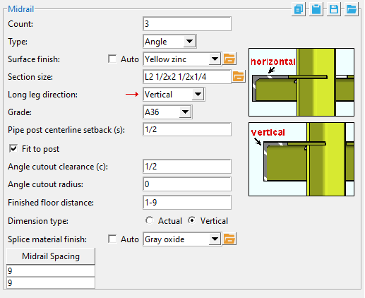
Angle Midrail
Section size: Any section size of the angle midrail that is in the local shape file . You can type in the section size that you want, or you can press the "file cabinet" browse button ( ![]() ) and double-click any section that is on the list of available materials in the local shape file. Validation only lets you enter a material that is listed in the local shape file.
) and double-click any section that is on the list of available materials in the local shape file. Validation only lets you enter a material that is listed in the local shape file.
Setup:Hand Rail Setup ( Home > Project Settings > Job > Plugin Defaults ...)
Long leg direction: Horizontal or Vertical .
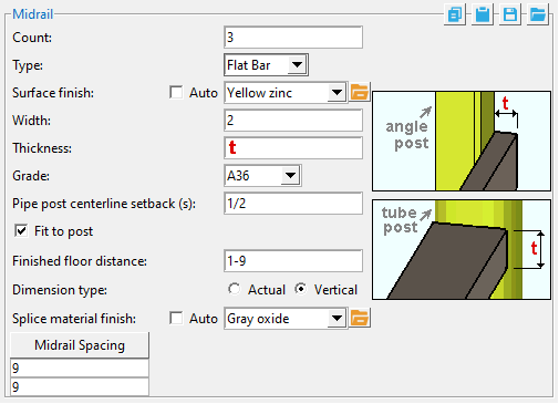
Flat Bar Midrail
Width: The " Material width " of the midrails.
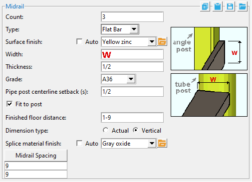
Thickness: The " Material thickness " of the midrails when their " Type " is ' Flat Bar '.
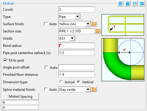
Pipe Midrail
Section Size: Any section size of the pipe or tube support that is in the local shape file . You can type in the section size that you want, or you can press the "file cabinet" browse button ( ![]() ) and double-click any section that is on the list of available materials in the local shape file. Validation only lets you enter a material that is listed in the local shape file.
) and double-click any section that is on the list of available materials in the local shape file. Validation only lets you enter a material that is listed in the local shape file.
Bend radius: A distance that defines the inside radius of bending for the bottom corner elbow of a P-end. This applies when the end " Condition " is ' P-End ' and the " Corner " is ' Elbow '. The distance entered here is exactly the same distance that is entered as the midrail's " Inside elbow radius " for each end that has a P-end.
Tube Midrail
Section Size: Any section size of the pipe or tube support that is in the local shape file . You can type in the section size that you want, or you can press the "file cabinet" browse button ( ![]() ) and double-click any section that is on the list of available materials in the local shape file. Validation only lets you enter a material that is listed in the local shape file.
) and double-click any section that is on the list of available materials in the local shape file. Validation only lets you enter a material that is listed in the local shape file.
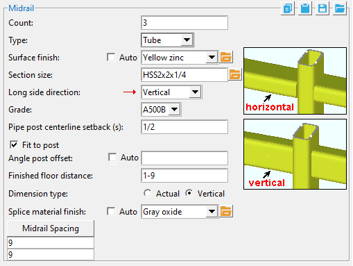
Long side direction: Horizontal or Vertical . This sets whether that long side is horizontal or vertical to the world. .
Grade: A36 or A572 or etc. The steel grade of the material. Steel grades that are available for a particular material depend on the type of that material. If the grade of steel that you want is not shown as a menu option ( ![]() ) on the Hand Rail window, you can add the grade you want to the setup table.
) on the Hand Rail window, you can add the grade you want to the setup table.
| Material Type |
Job Settings Table
|
Material Window |
| angle | Angle Grades | " Steel grade " |
| HSS round | Pipe Grades | |
| HSS rectangular | HSS/TS Grades | |
| W tee | WT Grades | |
| flat bar | Round and Square Bar Grades or Plate Grades | " Steel grade " |
| round bar | " Steel grade " | |
| square bar | " Steel grade " | |
| bent plate | Plate Grades | " Steel grade " |
| rectangular plate | " Steel grade " | |
| round plates | " Steel grade " | |
| Also see : Click here for information on the handrail parts that these material types are used for. | ||
Warning : Do not set a handrail part's steel grade on its material windows -- instead use the Hand Rail window. Changing material information on a material window instead of the Hand Rail window makes the handrail graphical .
Setup: Hand Rail Setup ( Home > Project Settings > Plugin Defaults ...)
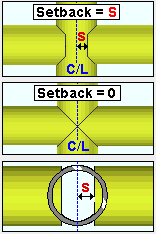
Pipe post centerline setback: The vertical distance from the centerline of the pipe post to the edge of the midrail.
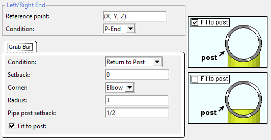
Fit to post:
![]() or
or ![]() . This option is enabled when ' Pipe ' is the " Type " of post. You can fit a pipe, tube or angle midrail to a pipe post.
. This option is enabled when ' Pipe ' is the " Type " of post. You can fit a pipe, tube or angle midrail to a pipe post.
|
( pipe to pipe )  |
 |
( tube to pipe )  |
( angle to pipe )  |
If this box is checked (
If this box is not checked (
Note: In the example shown for angle to pipe, the top rail " Type " is set to ' Angle ', which causes the heel of the angle to align with the work ine .
Angle cutout clearance: The distance between the edge of the angle post and the edge of the midrail cutout. This option is enabled when ' Angle ' is both the post " Type " and the " Type " of midrail. This cutout is made to the horizontal leg of the angle that is used for the midrail. It allows the angle post to align flush with the vertical leg of the midrail.
Angle cutout radius: A distance. A value of ' 0 ' makes the corner squared. Increasing the radius makes the curve more gradual. This is the same corner rounding algorithm that is used for Cut Layout . This applies to the corners of the " Angle cut " when ' Angle ' is both the post " Type " and the " Type " of midrail.
Vertical and horizontal construction lines at the vertex points ( vtpt ) of the corner cut meet at the center point of a construction circle whose " Radius " is equal to the " Angle cutout radius ."
Angle post offset: ![]() Auto or
Auto or ![]() Auto . This applies when the " Type " of post is ' Angle ' and the " Type " of midrail is ' Pipe ' or ' Tube '.
Auto . This applies when the " Type " of post is ' Angle ' and the " Type " of midrail is ' Pipe ' or ' Tube '.
'
'
Finished floor distance: The actual or vertical distance that the bottom midrail is above the " Floor thickness ." In the example below, the construction line through the work point (wkpt) shows the top of steel workline established by the points that were located when the handrail was added.
solids form
stick form
Dimension type: Actual or Vertical . If the handrail is not sloping, the ' Vertical ' distance is measured the same as the ' Actual ' distance since both are measured perpendicular to the floor and bottom midrail. For a sloping handrail, the distances are different.
' Actual ' sets the " Finished floor distance " to be measured as the shortest distance (a perpendicular) between the bottom midrail and the floor. ' Vertical ' sets the " Finished floor distance " to be measured vertically between bottom midrail and the finished floor.
Splice Material Finish: Sets the splice connection material finish .
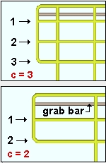
Midrail spacing: The distance between midrails (bottom listed first, top listed last). The number of entries ( lines ) shown here equals the " Count " ( count ) of midrails minus 1; that is, lines = count - 1 . This means that if the " Count " is ' 1 ', there are no lines for " Midrail spacing ." If the " Count " is ' 2 ', there is one line. If the " Count " is ' 3 ', there are two lines.
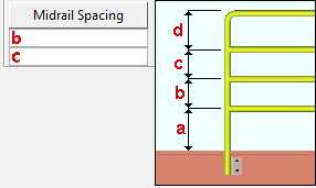
c is the distance from the center of that middle midrail to the top midrail.
The distance from the workline to the center of the bottom rail ( a ) is equal to the " Floor thickness " ( ft ) plus the " Finished floor distance "
Posts/Pickets Tab
Post
Surface finish: None or Sandblasted or Red oxide or Yellow zinc or Gray oxide or Blued steel or Galvanized or Duplex Coating or Undefined 1 or Undefined 2 or Undefined 3 or Red oxide 2 or Any user added surface finish. This affects the colors of Solid members on erection views in the Drawing Editor . This also sets the color when Output material color is set to Surface finish for a VRML Export or a DWG/DXF Export. The Color (not Surface finish) sets the color of this material in Modeling .
| sand blasted | red oxide | yellow zinc | user surface finish 1 |
| gray oxide | blued steel | galvanized | user surface finish 2 |
To assign a different surface finish, you can drop-down the current surface finish and select the one you want, or you can press the
Auto ![]() or
or ![]()
If this box
If the box
Note 1: Submaterial piecemarks can be split apart by surface finish. All surface finishes that do not have the Break Marks Material checked on can be applied to any like material with out the material splitting. If the Break Marks Material is checked on then only like materials with that specific surface finish can have the same piecemark, and because the submaterial marks differ so would the member's piecemark.
Note 2: When exporting a KISS file using "model" as the Data source surface finish data on the materials are compiled into the KISS download as follows, with a few exceptions (G=galvanized, N= none or sandblasted, P= others). Those exceptions are:
If the box for Finish routing in KISS export setup is set to a user routing
If the user has adjusted the Abbreviation for any of the default provided surface finishes
If you are using a user added surface finish
In these cases you will get what is provided in either the User routing, or the abbreviation field. For other exports it will always provide the abbreviation in the 'surface finishes' settings page.
Tip 1: Surface area is reported on the General Information window -- and this can be used to estimate the amount of coating required and its cost.
Tip 2: Changing Steel grade, Color, and Surface finish do not cause the plate to be regenerated. This means that, if you change those settings only, material fit operations such as a Fit Exact may optionally be preserved.
Report Writer: MemberMaterial.Material.SurfaceFinish
Setup: Surface Finish Settings
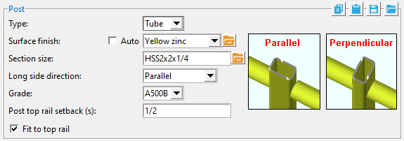
Section size: Any section size of the specified material type that is in the local shape file . You can type in the section size that you want, or you can press the "file cabinet" browse button ( ![]() ) and double-click any section that is on the list of available materials in the local shape file. Validation only lets you enter a material that is listed in the local shape file.
) and double-click any section that is on the list of available materials in the local shape file. Validation only lets you enter a material that is listed in the local shape file.
Setup: Hand Rail Setup ( Home > Project Settings > Job > Plugin Defaults ...)
Long side direction: Parallel or Perpendicular .
' Parallel ' sets the long side of the tube to be parallel to the " Reference line " of the handrail.
' Perpendicular ' sets the long side of the tube to be perpendicular to the reference line of the handrail.
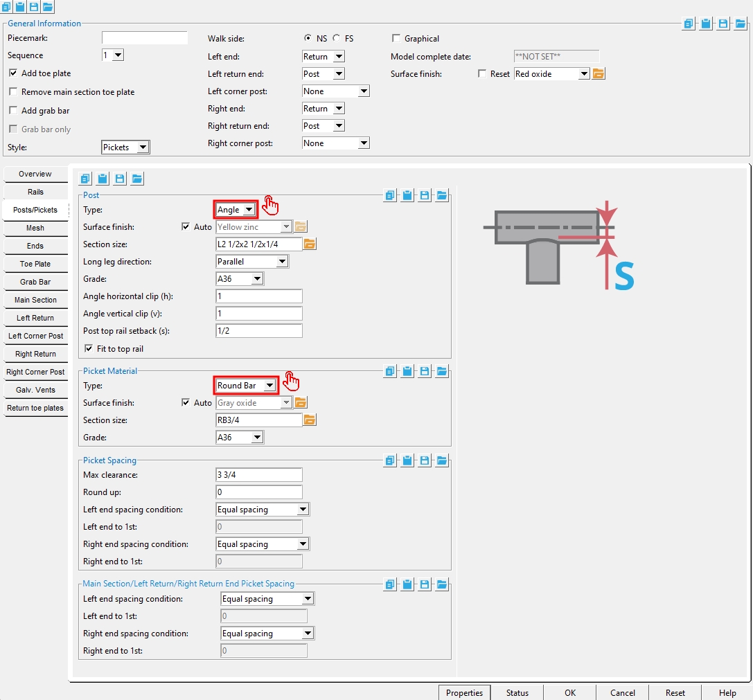
Long leg direction: Parallel or perpendicular . This applies when the post " Type " is an ' Angle ' with a " Section size " that has unequal legs. It sets the long leg of the angle to be parallel or perpendicular to the " Reference line " of the handrail.
| Post: |
' Parallel '
|
' Perp ' | |
|
|
|
||
| These views look down the " Reference line ." All angles are 3x2x1/4. The top rail's " Long leg direction " is set under the " Rails " tab. | |||
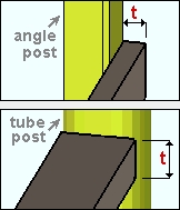
Angle horizontal clip (CH): The horizontal distance from the vertical edge of the post to where the corner of the clip meets the top (horizontal) edge of the post.
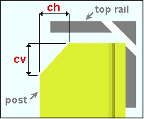
Angle vertical clip (CV): The vertical distance from the top of the post to where the corner of the clip meets the vertical edge of the post.
Grade: A36 or A572 or etc. The steel grade of the material. Steel grades that are available for a particular material depend on the type of that material. If the grade of steel that you want is not shown as a menu option ( ![]() ) on the Hand Rail window, you can add the grade you want to the setup table.
) on the Hand Rail window, you can add the grade you want to the setup table.
Setup: Hand Rail Setup ( Home > Project Settings > Plugin Default s...)
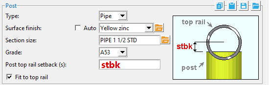
Post top rail setback: A distance. This option is disabled (grayed out) for situations where a top setback cannot be applied. This applies to all post types when ' Pipe ' is the " Type " of top rail. It also applies when ' Angle ' is the " Type " of top rail and ' Angle ' is the " Type ' of post. The position of the top rail remains the same regardless of the entry made here. The entry made here adjusts the length of the posts. For a pipe top rail, this setback is the distance from the top edge of the post to the centerline of the pipe top rail. For an angle post to an angle top rail, this setback is the distance from the top of the angle post to the bottom of the horizontal leg of the top rail.
Fit to top rail:
![]() or
or ![]() . This option is enabled when ' Pipe ' is the " Type " of top rail. You can fit a pipe, tube or angle post to a pipe top rail.
. This option is enabled when ' Pipe ' is the " Type " of top rail. You can fit a pipe, tube or angle post to a pipe top rail.
|
(pipe to pipe)  |
(pipe to pipe)  |
(tube to pipe)  |
(angle to pipe)  |
If this box is checked (
If this box is not checked (
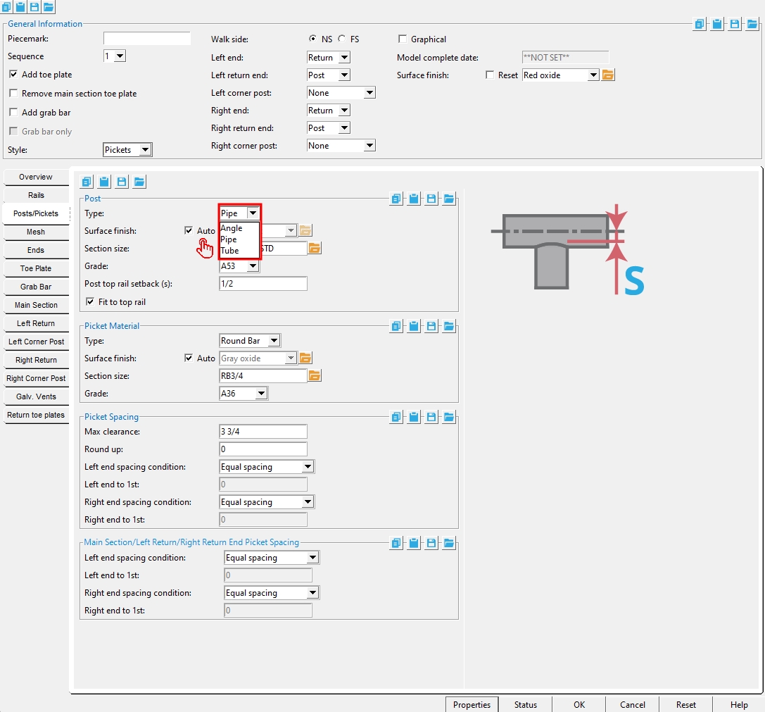
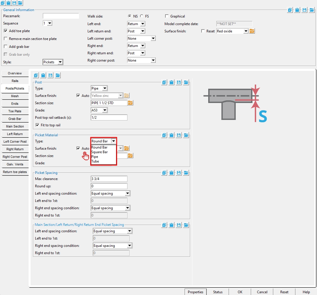
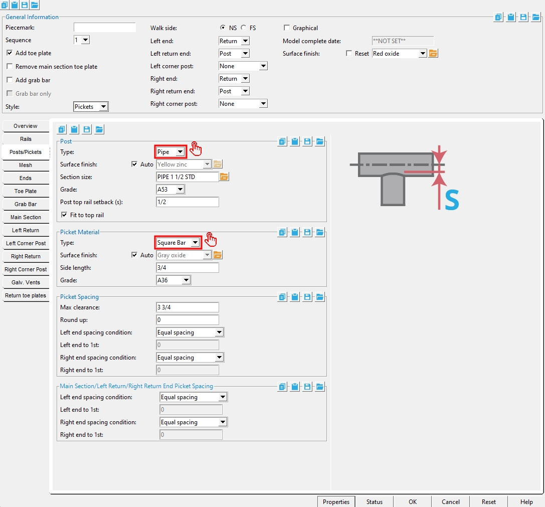
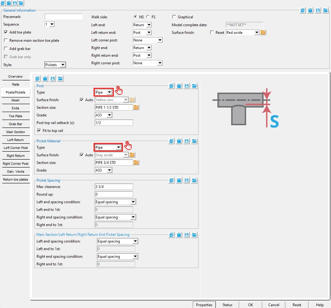
Picket Material
Type: Round Bar or Square Bar or Pipe or Tube . This applies when the " Style " under " General Information " is set to ' Pickets '.
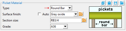
Surface finish: None or Sandblasted or Red oxide or Yellow zinc or Gray oxide or Blued steel or Galvanized or Duplex Coating or Undefined 1 or Undefined 2 or Undefined 3 or Red oxide 2 or Any user added surface finish. This affects the colors of Solid members on erection views in the Drawing Editor . This also sets the color when Output material color is set to Surface finish for a VRML Export or a DWG/DXF Export. The Color (not Surface finish) sets the color of this material in Modeling .
| sand blasted | red oxide | yellow zinc | user surface finish 1 |
| gray oxide | blued steel | galvanized | user surface finish 2 |
To assign a different surface finish, you can drop-down the current surface finish and select the one you want, or you can press the
Auto ![]() or
or ![]()
If this box
If the box
Note 1: Submaterial piecemarks can be split apart by surface finish. All surface finishes that do not have the Break Marks Material checked on can be applied to any like material with out the material splitting. If the Break Marks Material is checked on then only like materials with that specific surface finish can have the same piecemark, and because the submaterial marks differ so would the member's piecemark.
Note 2: When exporting a KISS file using "model" as the Data source surface finish data on the materials are compiled into the KISS download as follows, with a few exceptions (G=galvanized, N= none or sandblasted, P= others). Those exceptions are:
If the box for Finish routing in KISS export setup is set to a user routing
If the user has adjusted the Abbreviation for any of the default provided surface finishes
If you are using a user added surface finish
In these cases you will get what is provided in either the User routing, or the abbreviation field. For other exports it will always provide the abbreviation in the 'surface finishes' settings page.
Tip 1: Surface area is reported on the General Information window -- and this can be used to estimate the amount of coating required and its cost.
Tip 2: Changing Steel grade, Color, and Surface finish do not cause the plate to be regenerated. This means that, if you change those settings only, material fit operations such as a Fit Exact may optionally be preserved.
Report Writer: MemberMaterial.Material.SurfaceFinish
Setup: Surface Finish Settings
Grade: A36 or A572 or etc. The steel grade of the material. Steel grades that are available for a particular material depend on the type of that material. If the grade of steel that you want is not shown as a menu option ( ![]() ) on the Hand Rail window, you can add the grade you want to the setup table.
) on the Hand Rail window, you can add the grade you want to the setup table.
Setup: Hand Rail Setup ( Home > Project Settings > Plugin Default s...)
Section size: Any section size of the specified material type that is in the local shape file . You can type in the section size that you want, or you can press the "file cabinet" browse button ( ![]() ) and double-click any section that is on the list of available materials in the local shape file. Validation only lets you enter a material that is listed in the local shape file.
) and double-click any section that is on the list of available materials in the local shape file. Validation only lets you enter a material that is listed in the local shape file.
Setup: Hand Rail Setup ( Home > Project Settings > Job > Plugin Defaults ...)
Side length: The " Material width " of the pickets.
Long side direction: Parallel or Perpendicular . This applies when the " Type " of pickets is a ' Tube ' that has a " Section size " with one side longer than the other.
' Parallel ' sets the long side of the tube to be parallel to the " Reference line " of the handrail. Top rails and midrails also run parallel with the reference line.
' Perpendicular ' sets the long side of the tube to be parallel to the " Reference line " of the handrail.
Picket Spacing
Max clearance: . The maximum horizontal clearance between pickets. Max clearance sets the clearance between pickets and posts as measured from the outside of their material.
Tip: In most cases, entering a " Max clearance " that is exactly the maximum allowable opening by code while entering a " Round up " greater than zero will result in least number of pickets that can be spaced while still ensuring code compliance.
Round up: A distance to which the picket clearances should be rounded. Entries made here change the picket clearances, and in turn affect picket dimensioning when the member is detailed.
| example | maximum clearance | width of pickets | space inside posts | round up | number of pickets | total spaces |
picket clearance
|
| 1 | 3 3/4 | 3/4 | 41 1/4 | 0 | 9 | 10 | 3 7/16 (3.45) |
| 2 | 3 3/4 | 3/4 | 41 1/4 | 1/16 | 9 | 10 |
2@3 1/4 (3.25),
8@3 1/2 (3.5) |
Example 1: When " Round up " is ' 0 ' and left and right end spacing conditions are set to " Equal spacing " (see below), the pickets are all equally spaced. However, the displayed clearance dimension (3 7/16" × 10 spaces) when added to the widths of the pickets (3/4' × 9 pickets") is less than the overall dimension of 41 1/4" (that is, 41 1/8").
Example 2: Entering a " Round up " value of ' 1/16' ensures that the sum of dimensions of the picket clearance (3 1/2" x 8 spaces, 3 1/4" x 2 spaces) and pickets (3/4' × 9 pickets") is equal to the overall dimension of the space inside the posts (that is, 41 1/4"). In this case, the extra space is added to the spaces next to the posts on either end of the section.
Also see: Hand Rail Setup (sets picket dimensioning options for template detailing)
Left end spacing condition: Equal spacing or Setback from point .
' Equal spacing ' spaces the leftmost picket in the section or return using the " Max clearance ," adjusted to the " Round up " distance.
' Setback from point ' spaces the leftmost picket using the " Left end to 1st " distance.
Left end to 1st: A distance by which the leftmost picket in a section or return is spaced from post to its left. This applies when " Left end spacing condition " is
Right end spacing condition:Equal spacing or Setback from point . Equal spacing or Setback from point .
' Equal spacing ' spaces the rightmost picket in the section or return using the " Max clearance ," adjusted to the " Round up " distance.
' Setback from point ' spaces the rightmost picket using the " Right end to 1st " distance.
Right end to 1st: A distance by which the rightmost picket in a section or return is spaced from post to its left. This applies when
Main Section / Left Return / Right Return End Picket Spacing
Left end spacing condition: Equal spacing or Setback from point .
' Equal spacing ' spaces the leftmost picket in the section or return using the " Max clearance ," adjusted to the " Round up " distance.
' Setback from point ' spaces the leftmost picket using the " Left end to 1st " distance.
Left end to 1st: A distance by which the leftmost picket in a section or return is spaced from post to its left. This applies when " Left end spacing condition " is
Right end spacing condition:Equal spacing or Setback from point . Equal spacing or Setback from point .
' Equal spacing ' spaces the rightmost picket in the section or return using the " Max clearance ," adjusted to the " Round up " distance.
' Setback from point ' spaces the rightmost picket using the " Right end to 1st " distance.
Right end to 1st: A distance by which the rightmost picket in a section or return is spaced from post to its left. This applies when
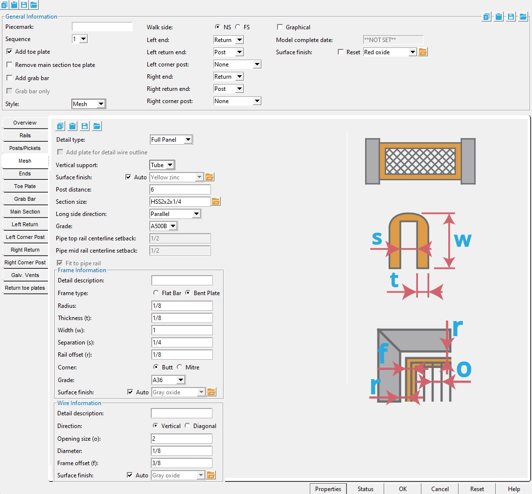
Mesh Tab
Detail type: Full panel or Inset .
' Full panel '
|
' Inset '
|
' Full panel ' models the wire component of the mesh using grating tread material whose " Grating width " and " Grating length " are automatically set to values that fit the grating tread snugly inside the mesh frame per whatever " Frame offset " is entered.
' Inset ' also models the wire component of the mesh, but as a small rectangular "swatch" of the wire material floating in space. This may be less accurate, but potentially results in a more attractive (less busy) hand rail detail.
Add plate for detail wire outline:
![]() or
or ![]() . This applies when the " Detail type " is ' Inset '.
. This applies when the " Detail type " is ' Inset '.
|
If this box is checked (
If the box is not checked (
Vertical support: Pipe or Post or Tube .
Post: No extra supports are added, the posts are the mesh supports.
Pipe/Tube: Vertical pipe or tube supports are added at whatever distance is specified from the posts.
Surface finish: None or Sandblasted or Red oxide or Yellow zinc or Gray oxide or Blued steel or Galvanized or Duplex Coating or Undefined 1 or Undefined 2 or Undefined 3 or Red oxide 2 or Any user added surface finish. This affects the colors of Solid members on erection views in the Drawing Editor . This also sets the color when Output material color is set to Surface finish for a VRML Export or a DWG/DXF Export. The Color (not Surface finish) sets the color of this material in Modeling .
| sand blasted | red oxide | yellow zinc | user surface finish 1 |
| gray oxide | blued steel | galvanized | user surface finish 2 |
To assign a different surface finish, you can drop-down the current surface finish and select the one you want, or you can press the
Auto ![]() or
or ![]()
If this box
If the box
Note 1: Submaterial piecemarks can be split apart by surface finish. All surface finishes that do not have the Break Marks Material checked on can be applied to any like material with out the material splitting. If the Break Marks Material is checked on then only like materials with that specific surface finish can have the same piecemark, and because the submaterial marks differ so would the member's piecemark.
Note 2: When exporting a KISS file using "model" as the Data source surface finish data on the materials are compiled into the KISS download as follows, with a few exceptions (G=galvanized, N= none or sandblasted, P= others). Those exceptions are:
If the box for Finish routing in KISS export setup is set to a user routing
If the user has adjusted the Abbreviation for any of the default provided surface finishes
If you are using a user added surface finish
In these cases you will get what is provided in either the User routing, or the abbreviation field. For other exports it will always provide the abbreviation in the 'surface finishes' settings page.
Tip 1: Surface area is reported on the General Information window -- and this can be used to estimate the amount of coating required and its cost.
Tip 2: Changing Steel grade, Color, and Surface finish do not cause the plate to be regenerated. This means that, if you change those settings only, material fit operations such as a Fit Exact may optionally be preserved.
Report Writer: MemberMaterial.Material.SurfaceFinish
Setup: Surface Finish Settings
Post Distance: The distance from the post to the vertical pipe or tube support. This option
Note: This option is only available when " Vertical Support " is set to 'Pipe' or 'Tube'.
Section Size: Any section size of the pipe or tube support that is in the local shape file . You can type in the section size that you want, or you can press the "file cabinet" browse button ( ![]() ) and double-click any section that is on the list of available materials in the local shape file. Validation only lets you enter a material that is listed in the local shape file.
) and double-click any section that is on the list of available materials in the local shape file. Validation only lets you enter a material that is listed in the local shape file.
Note: This option is only available when " Vertical Support " is set to 'Pipe' or 'Tube'.
Long side direction: (' Parallel ' or ' Perpendicular ') applies when the " Vertical support " is a ' Tube ' that has a " Section size " with one side longer than the other. It sets the long side of the tube to be parallel or perpendicular to the " Reference line " of the handrail.
Note: This option is only available when " Vertical Support " is set to 'Tube'.
Grade: A53 or A500B or etc. The steel grade of the material. Steel grades that are available for a particular material depend on the type of that material. If the grade of steel that you want is not shown as a menu option ( ![]() ) on the Hand Rail window, you can add the grade you want to the setup table.
) on the Hand Rail window, you can add the grade you want to the setup table.
Pipe top rail centerline setback: The vertical distance from the centerline of the support to the edge of the top rail.
Pipe midrail centerline setback: The vertical distance from the centerline of the support to the edge of the midrail.
Fit to pipe rail: This option is enabled when ' Pipe ' is the type of post or top rail or midrail that you are fitting to. It applies when the setback from the center of the pipe is less than half of the pipe's depth, creating a situation where, if there was no fit operation, the material would clash with the pipe.
(pipe to pipe)
(pipe to pipe)
(tube to pipe)If this box is checked (
If this box is not checked (
Frame Information
Detail description: A string of any number of characters .
This is the " Description " on the material's General Information window and, after detailing, the
You may want to enter a description that matches the reference used for that material in the catalog you are ordering the material from.
Frame Type: Flat Bar or Bent Plate.
Flat Bar mesh frame consists of eight flat bars that sandwich the wire. On a non-sloping handrail, four of the flat bars are horizontal, and the four others are vertical. The largest picture in the example below shows dimensions on the top two horizontal flat bars.
Bent Plate mesh frame is made up of a four multi-bend plates . On a non-sloping handrail, two of these bent plates will be horizontal, but pointing in opposite directions. The largest picture in the example below has dimensions shown on the top horizontal bent plate, which points down. The vertical bent plate the is depicted points in and has the same dimensions -- its dimensions look different because of the view.
Radius: The bend radius of the bent plate frame.
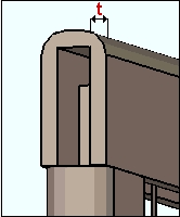
Thickness: The thickness of the ' Flat Bar 'or ' Bent Plate ' materials.
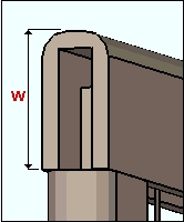
Width: The width (height) of the ' Flat Bar 'or ' Bent Plate ' material.
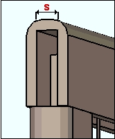
Separation: The gap between the ' Flat Bars 'or the distance between the legs of the ' Bent Plate '.
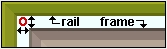
Rail offset: The distance the frame is offset from the rail.
Butt sets ' Flat Bar 'or ' Bent Plate ' materials square cut and fit against each material.
Mitre sets ' Flat Bar 'or ' Bent Plate 'materials fit to each other at a 45° angle.
Grade: A36 or A572 or etc. The steel grade of the material. Steel grades that are available for a particular material depend on the type of that material. If the grade of steel that you want is not shown as a menu option ( ![]() ) on the Hand Rail window, you can add the grade you want to the setup table.
) on the Hand Rail window, you can add the grade you want to the setup table.
Surface finish: None or Sandblasted or Red oxide or Yellow zinc or Gray oxide or Blued steel or Galvanized or Duplex Coating or Undefined 1 or Undefined 2 or Undefined 3 or Red oxide 2 or Any user added surface finish. This affects the colors of Solid members on erection views in the Drawing Editor . This also sets the color when Output material color is set to Surface finish for a VRML Export or a DWG/DXF Export. The Color (not Surface finish) sets the color of this material in Modeling .
| sand blasted | red oxide | yellow zinc | user surface finish 1 |
| gray oxide | blued steel | galvanized | user surface finish 2 |
To assign a different surface finish, you can drop-down the current surface finish and select the one you want, or you can press the
Auto ![]() or
or ![]()
If this box
If the box
Note 1: Submaterial piecemarks can be split apart by surface finish. All surface finishes that do not have the Break Marks Material checked on can be applied to any like material with out the material splitting. If the Break Marks Material is checked on then only like materials with that specific surface finish can have the same piecemark, and because the submaterial marks differ so would the member's piecemark.
Note 2: When exporting a KISS file using "model" as the Data source surface finish data on the materials are compiled into the KISS download as follows, with a few exceptions (G=galvanized, N= none or sandblasted, P= others). Those exceptions are:
If the box for Finish routing in KISS export setup is set to a user routing
If the user has adjusted the Abbreviation for any of the default provided surface finishes
If you are using a user added surface finish
In these cases you will get what is provided in either the User routing, or the abbreviation field. For other exports it will always provide the abbreviation in the 'surface finishes' settings page.
Tip 1: Surface area is reported on the General Information window -- and this can be used to estimate the amount of coating required and its cost.
Tip 2: Changing Steel grade, Color, and Surface finish do not cause the plate to be regenerated. This means that, if you change those settings only, material fit operations such as a Fit Exact may optionally be preserved.
Report Writer: MemberMaterial.Material.SurfaceFinish
Setup: Surface Finish Settings
Wire Information
Detail description: A string of any number of characters .
This is the " Description " on the material's General Information window and, after detailing, the
You may want to enter a description that matches the reference used for that material in the catalog you are ordering the material from.
Direction: Vertical or Diagonal. Sets the direction the bearing bars run on the mesh.
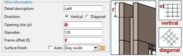
Opening Size:The distance between bars in the mesh material.

Diameter: the " Bearing bar depth " and the " Bearing bar thickness " and the " Cross bar depth " and " Cross bar thickness " of the grating tread material that is used to model the wire. The wire is modeled as having a square cross section.
Frame Offset: The offset of the mesh material from the edge of the frame.
Surface finish: None or Sandblasted or Red oxide or Yellow zinc or Gray oxide or Blued steel or Galvanized or Duplex Coating or Undefined 1 or Undefined 2 or Undefined 3 or Red oxide 2 or Any user added surface finish. This affects the colors of Solid members on erection views in the Drawing Editor . This also sets the color when Output material color is set to Surface finish for a VRML Export or a DWG/DXF Export. The Color (not Surface finish) sets the color of this material in Modeling .
| sand blasted | red oxide | yellow zinc | user surface finish 1 |
| gray oxide | blued steel | galvanized | user surface finish 2 |
To assign a different surface finish, you can drop-down the current surface finish and select the one you want, or you can press the
Auto ![]() or
or ![]()
If this box
If the box
Note 1: Submaterial piecemarks can be split apart by surface finish. All surface finishes that do not have the Break Marks Material checked on can be applied to any like material with out the material splitting. If the Break Marks Material is checked on then only like materials with that specific surface finish can have the same piecemark, and because the submaterial marks differ so would the member's piecemark.
Note 2: When exporting a KISS file using "model" as the Data source surface finish data on the materials are compiled into the KISS download as follows, with a few exceptions (G=galvanized, N= none or sandblasted, P= others). Those exceptions are:
If the box for Finish routing in KISS export setup is set to a user routing
If the user has adjusted the Abbreviation for any of the default provided surface finishes
If you are using a user added surface finish
In these cases you will get what is provided in either the User routing, or the abbreviation field. For other exports it will always provide the abbreviation in the 'surface finishes' settings page.
Tip 1: Surface area is reported on the General Information window -- and this can be used to estimate the amount of coating required and its cost.
Tip 2: Changing Steel grade, Color, and Surface finish do not cause the plate to be regenerated. This means that, if you change those settings only, material fit operations such as a Fit Exact may optionally be preserved.
Report Writer: MemberMaterial.Material.SurfaceFinish
Setup: Surface Finish Settings
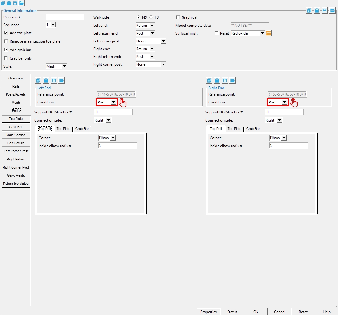
Ends Tab
This tells you the location of the work point at this end. The location is reported as a point (X, Y, Z), where X, Y and Z are global coordinates .
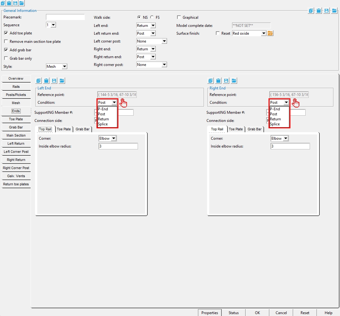
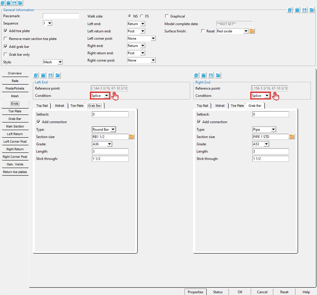
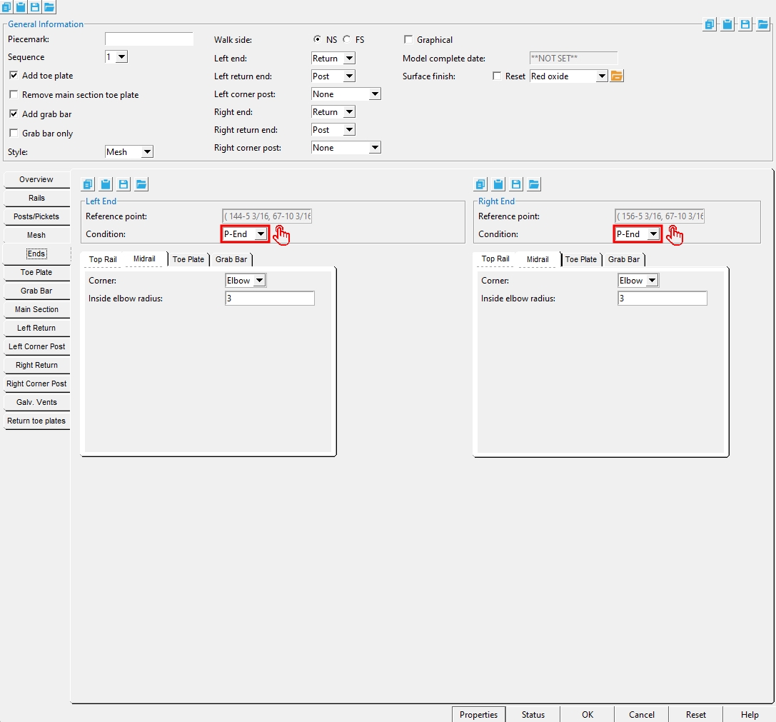
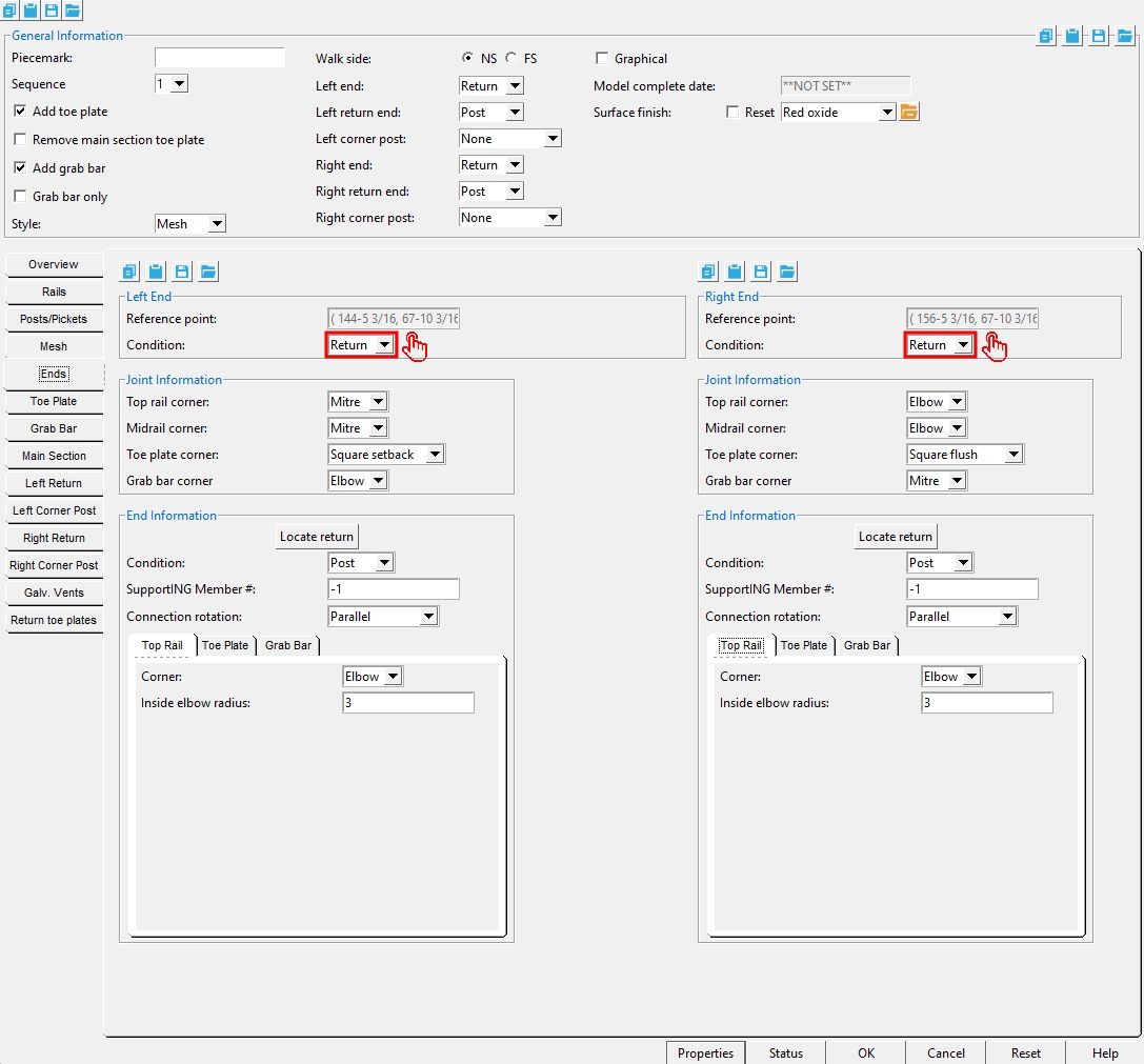
Condition: P-End or Post or Return or Splice . This sets the end condition for the main section.
' P-End ' applies when the posts and rails are pipe or tube. The vertical section of the ' P-End ' will be made to match the top rail.
' Post ' applies when the posts and rails are pipe or tube or angle. The " Support " for this post is identified below.
' Return ' may be applied to a handrail of any type of material. This is the default selection if you located work points for a return when you added the handrail. You will need to set " Joint Information " for the top rail, midrail and grab bar corners. The end " Condition " for the return is set under
" End Information ." ' Splice ' applies when there is no return. You can optionally " Add connection " for a pipe or tube or angle top rail or " Add connection " for pipe or tube pr angle midrails or " Add connection " for a grab bar or choose a " Connection " for the toe plate.
Support: -1 or a number ( member number ). This " Support " field is visible (packed) when the left end or right end " Condition " is set to ' Post '.
' -1 ' indicates that there is no support for this post, for example, because the handrail was modeled in space . When a handrail does not have a support, the only " Type " of post connection that will work properly is the ' Welded ' connection or the ' Continuous Bottom Plate '.
A ' number ' identifies the member number of the member that serves as the support for this end post.
Note: This window tells you the " Support " for each post of a handrail. This " Support " is for the left- or right-end post. When you press " OK " (so that Create Solids is performed on the handrail), the support will also undergo Create Solids to ensure that matching holes are properly placed in it. If you delete the handrail, the support is either marked for Create Solids or made to automatically undergo Create Solids .
Connection side: Left or Center or Right . This applies when the " Type " of post is ' Pipe ' or ' Tube ' and the " Type " of connection is ' Bent Plate ' or ' Clip angle ' or ' Shear Tab ' or ' W Tee '.
|
' Center ' is only for ' Shear Tab ' or ' W Tee '. It is your responsibility to size your connection materials to prevent material clashes -- the Hand Rail program does not size the materials for you.
Toe direction: Right or Left . This applies when the " Type " of post is ' Angle '.
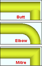
Top rail corner: Elbow or Mitre or Butt . This applies when the " Condition " for this end of the main section is ' Return '.
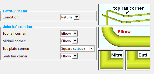
' Elbow ' can get good results when the " Type " of top rail is a ' Pipe ' or ' Tube '. It does not work for joining ' Angle ' or ' Flat bar ' top rails on the main section with the return.
' Mitre ' works when the " Type " of top rail is a ' Pipe ' or ' Tube ' or ' Flat bar ' or ' Angle '.
' Butt ' works when the " Type " of top rail is a ' Pipe ' or ' Tube ' or ' Flat bar ' or ' Angle '.
Midrail corner: Elbow or Mitre or Butt . This applies when the " Condition " for this end of the main section is ' Return '.
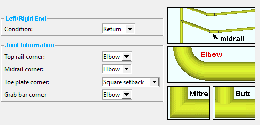
' Elbow ' can get good results when the " Type " of midrail is a ' Pipe ' or ' Tube '. It does not work for joining ' Angle ' or ' Flat bar ' midrails.
' Mitre ' works when the " Type " of midrail is a ' Pipe ' or ' Tube ' or ' Angle '.
' Butt ' works when the " Type " of midrail is a ' Pipe ' or ' Tube ' or ' Flat bar ' or ' Angle '.
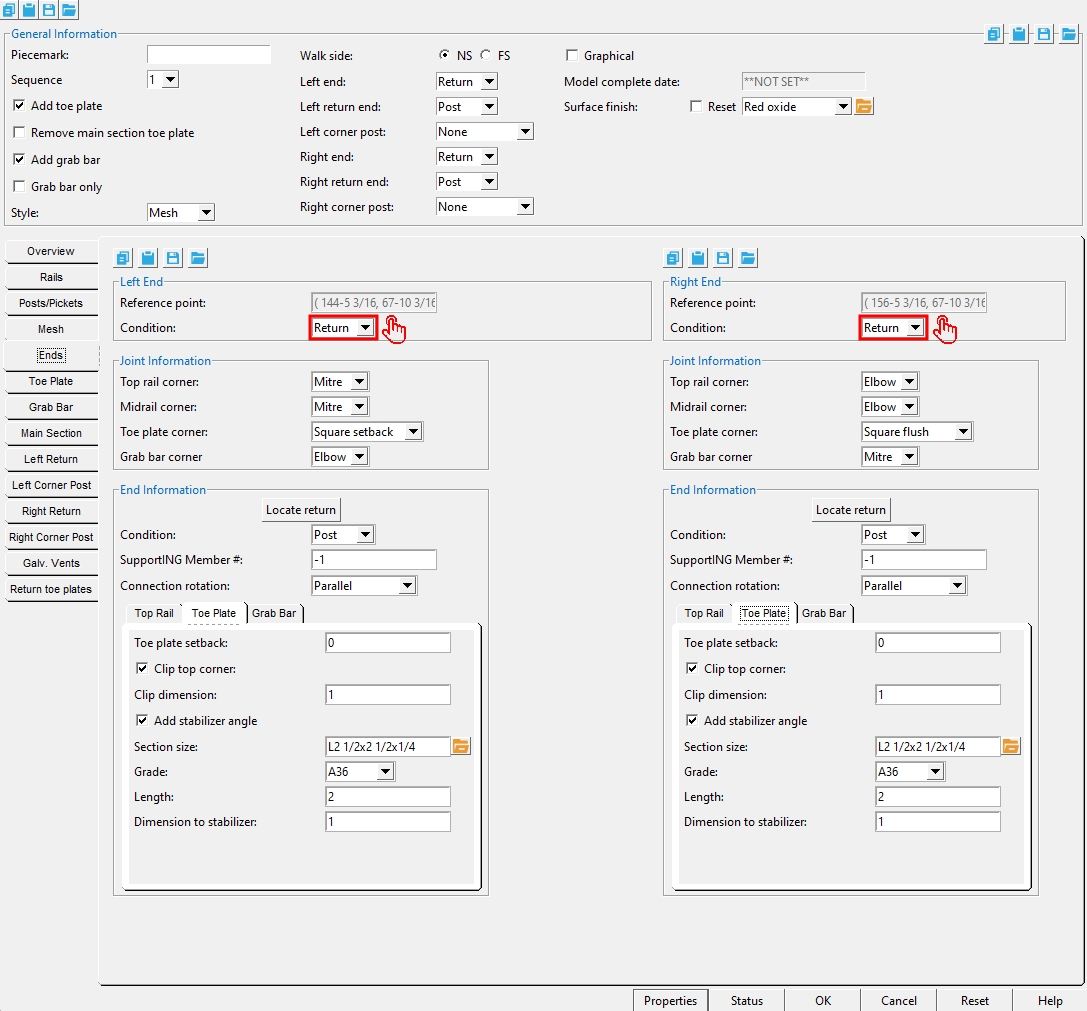
Toe plate corner :Mitre or Square Flush or Square Setback . This applies when the " Condition " for this end of the main section is ' Return ' and ![]() Add toe plate "
Add toe plate "
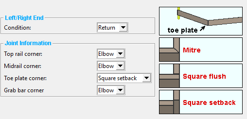
' Mitre ' works well with most corners, not just 90 degree corners. ' Mitre ' cuts the ends of the two toe plates at angles, resulting in the vertical edges of the two toe plates (their thickness edges) being flush to one another. The program can figures out the cuts that are needed based on the angle between the two toe plates.
' Square flush ' gives good results for 90 degree corners. Both toe plates are cut square. The return's toe plate butts flush to the main section's toe plate.
' Square Setback ' works well with all corners, not just 90 degree corners. Both toe plates are cut square. Each of the two toe plates meet at a single vertical corner. Neither toe plate is flush to the other.
Grab bar corner: Elbow or Mitre . This applies when the " Condition " for this end of the main section is ' Return ' and " ![]() Add grab bar " is turned on.
Add grab bar " is turned on.
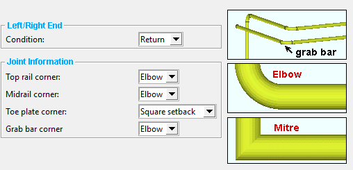
' Elbow ' can get good results when the " Type " of grab bar is a ' Pipe '. It does not work for joining ' Tube ' grab bars.
' Mitre ' works when the " Type " of grab bar is a ' Pipe ' or ' Tube '.
Locate Return : Hand Rail add window closes and provides you Locate - Pan - Return mouse bindings for locating points from the end of the handrail where you want the return to be located.
Note : You will want to be at the same elevation as the main section, otherwise the return will be sloping.
Corner: Butt or Elbow or Mitre .
' Butt ' is the only setting that works if the " Type " of post is ' Angle '.
' Elbow ' or ' Mitre ' work well when the " Type " of post is ' Pipe ' or ' Tube ' and the " Type " of top rail is a ' Pipe ' or ' Tube ' of the same size.
Inside elbow radius: This applies to pipe when the " Corner " is set to ' Elbow '.
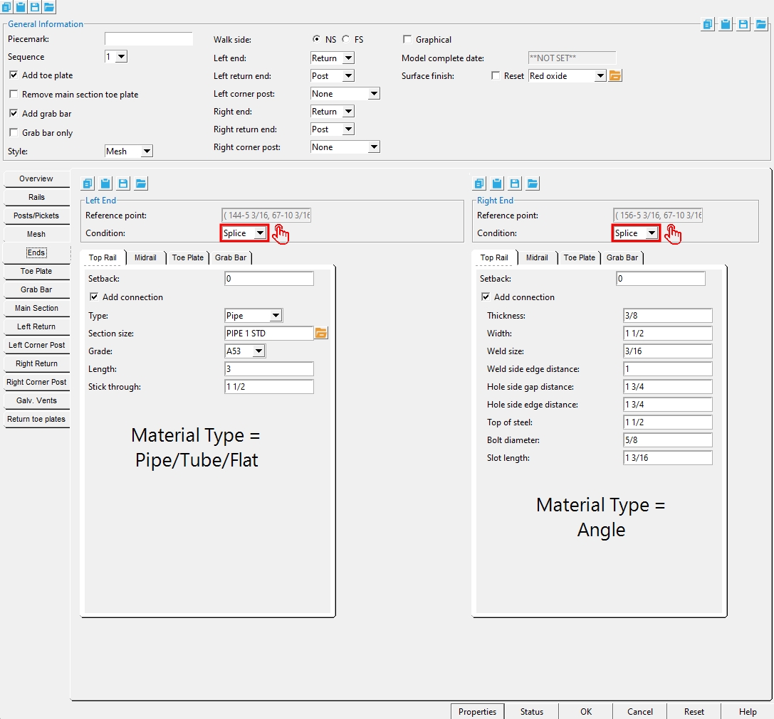
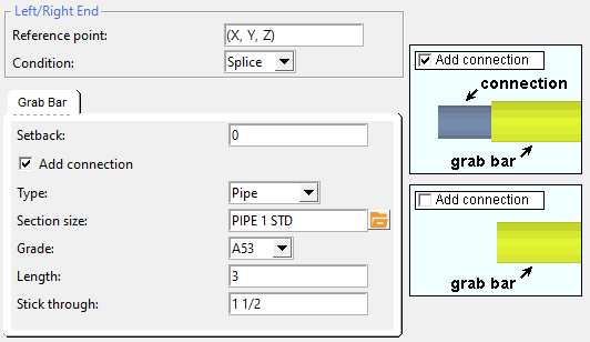
Setback: A positive or negative (-) distance. This applies when the main section end " Condition " is ' Splice '.
' 0 ' aligns the left end of the top rail with the handrail's left end work point.
A ' positive distance ' backs the top rail away from the left end toward the right end.
A ' negative (-) distance ' extends the top rail past the left end.
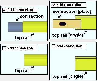
Add connection:
![]() or
or ![]() . This applies when the main section end " Condition " is ' Splice '. Top rail splice connection materials for pipe or tube top rails can be pipe or round bar. The connection material for angle top rails is a rectangular plate.
. This applies when the main section end " Condition " is ' Splice '. Top rail splice connection materials for pipe or tube top rails can be pipe or round bar. The connection material for angle top rails is a rectangular plate.
Type: Pipe or Round Bar . This applies when the main section end " Condition " is set to ' Splice ' and " Add connection " is checked ( ![]() ). " Length " ( len ) is the total length of the splice material. " Stick through " ( ST ) is the distance that the splice that the splice sticks out beyond the end of the top rail.
). " Length " ( len ) is the total length of the splice material. " Stick through " ( ST ) is the distance that the splice that the splice sticks out beyond the end of the top rail.
' Pipe ' requires that you enter a pipe " Section size " to be used as the top rail splice.
' Round Bar ' requires that you enter the " Section Size " of the round bar to be used for the top rail splice.
Section size: Any section size of the specified material type that is in the local shape file . You can type in the section size that you want, or you can press the "file cabinet" browse button ( ![]() ) and double-click any section that is on the list of available materials in the local shape file. Validation only lets you enter a material that is listed in the local shape file.
) and double-click any section that is on the list of available materials in the local shape file. Validation only lets you enter a material that is listed in the local shape file.
Grade: A36 or A572 or etc. The steel grade of the connection material. If the grade of steel that you want is not shown as a menu option ( ![]() ) on the Hand Rail window, you can add the grade you want to the setup table.
) on the Hand Rail window, you can add the grade you want to the setup table.
Length: The connection material length (len). Increasing the " Length " of the connection material adds the extra material toward the inside of the grab bar.
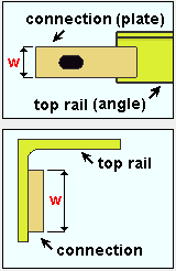
Thickness: The plate thickness of the connection plate for splicing the angle top rails.
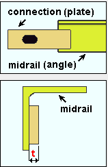
Width: The width of the connection plate for splicing the angle top rails.
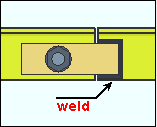
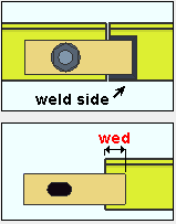
Weld size: The weld size for welding the weld side of the connection plate for splicing the angle top rails.
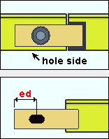
Weld side edge distance: The distancefrom the weld side edge of the connection plate to the edge of the angle top rail to which the connection plate welds.
Hole side gap distance: The distance from the edge of the angle top rail to which the connection plate bolts to the center of the hole for bolting to that same rail.
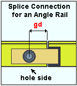
Hole side edge distance: The distance from the center of the hole for bolting the connection plate to the angle top rail to the hole side edge of the connection plate.
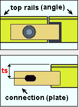
Top of steel: The distance from the center of the hole for bolting the connection plate to the angle top rail to the top of the angle top rail.
Bolt Diameter: The diameter of the shank of the bolt. This is also the " Diameter " of the bolt on its edit window.
| diameter |
|
The hole in the handrail that the bolt is inserted through is sized based on the bolt's " Diameter " and the " Type " of that hole.
Setup:Hand Rail Setup ( Home > Project Settings > Plugin Defaults... )
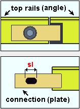
Slot length: The distance between the two points farthest from one another on the perimeter of a slot.
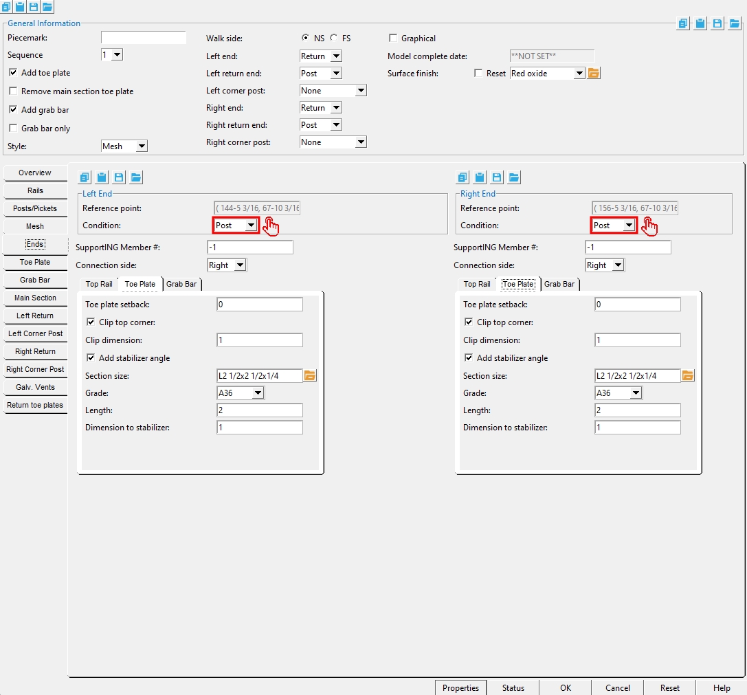
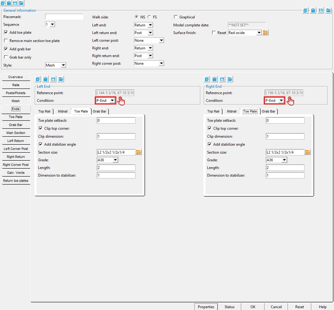
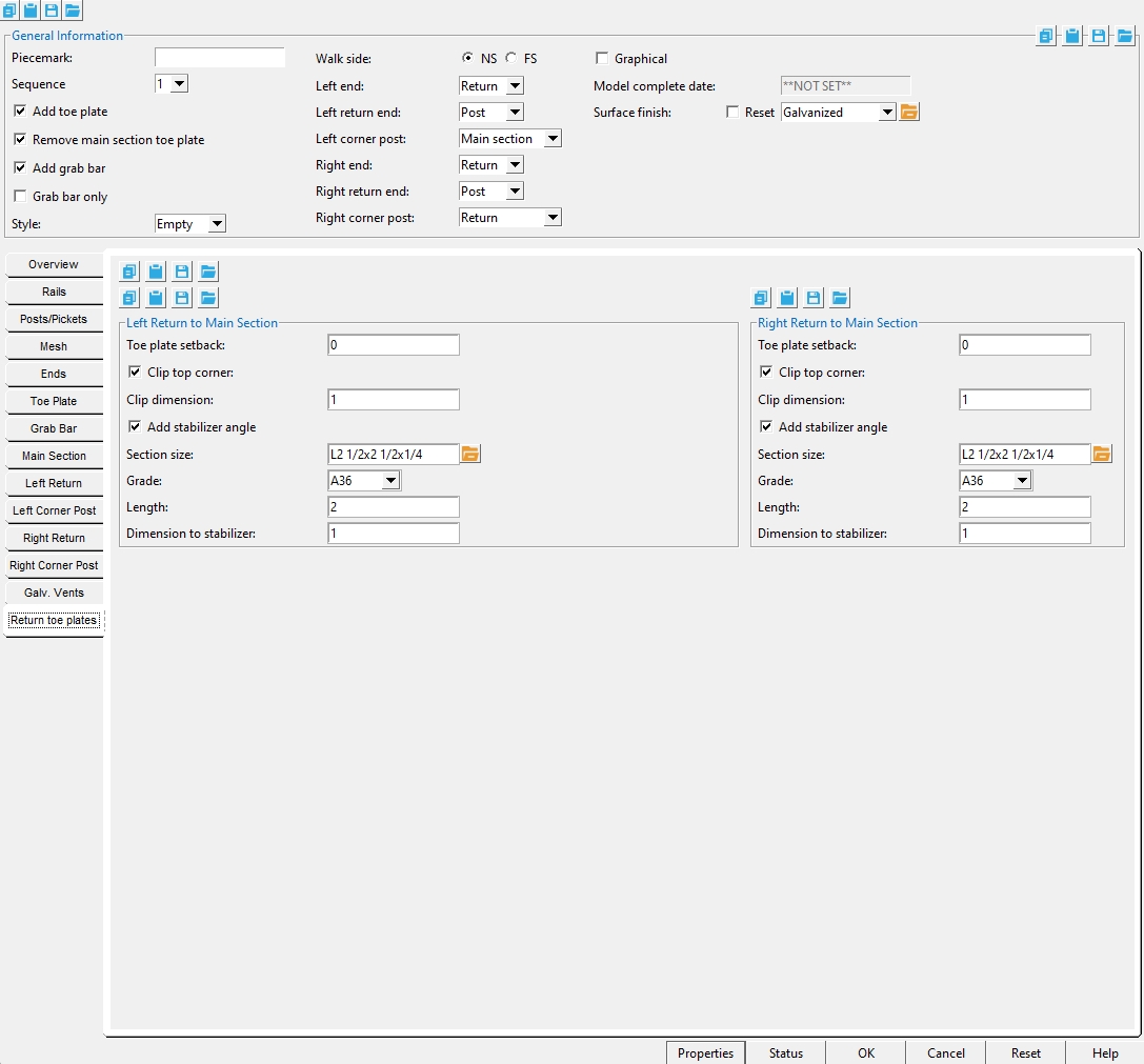
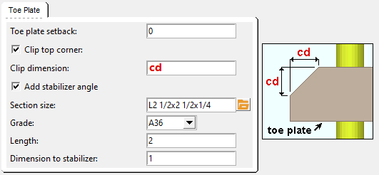
Toe plate setback: A positive or negative (-) distance.
- distance
0 (zero)
+ distance
A ' positive distance ' backs the toe plate away from the left-end work point toward the right end.
A ' negative (-) distance ' extends the toe plate past the end post.
Note: The work point aligns with the center of a pipe or tube end post if the top rail is the same material.
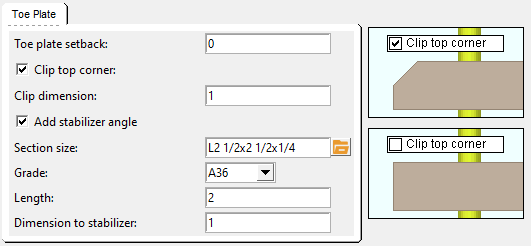
If this box is checked (
If the box is not checked (
Clip dimension: A distance. A distance greater than ' 0 ' applies a 45 degree cut to the top corner of the toe plate. ' 0 ' (zero) keeps the toe plate cut square.
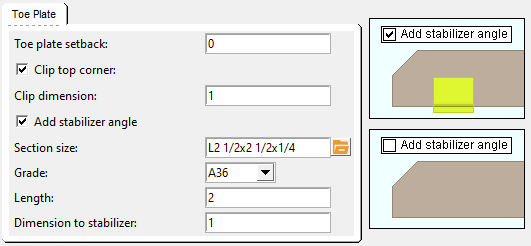
If this box is checked (
If the box is not checked (
Section size: Any section size of the specified material type that is in the local shape file . You can type in the section size that you want, or you can press the "file cabinet" browse button ( ![]() ) and double-click any section that is on the list of available materials in the local shape file. Validation only lets you enter a material that is listed in the local shape file.
) and double-click any section that is on the list of available materials in the local shape file. Validation only lets you enter a material that is listed in the local shape file.
Grade: A36 or A572 or etc. The steel grade of the stabilizer angle. If the grade of steel that you want is not shown as a menu option ( ![]() ) on the Hand Rail window, you can add the grade you want to the setup table.
) on the Hand Rail window, you can add the grade you want to the setup table.
Length: The stabilizer angle length. Increasing the " Length " of the stabilizer angle adds the extra material toward the inside of the toe plate.
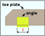
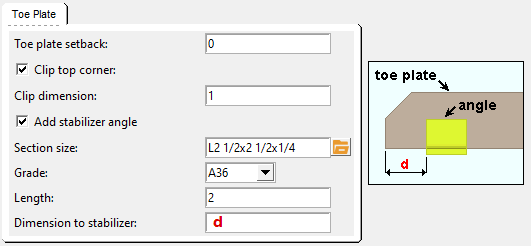
Distance to stabilizer: The distance from the outside edge of the toe plate to the outside edge of the stabilizer angle. The outside edge of the toe plate is positioned by the " Toe plate setback ."
Setback: A positive or negative (-) distance.
A ' positive distance ' backs the toe plate away from the left-end work point toward the right end.
A ' negative (-) distance ' extends the toe plate past the work point.
Connection: None or Plate or Hole . This option is available when the " Condition " for this end is ' Splice '.
' None ' stops a splice connection from being generated for the toe plate.
' Plate ' toe plate splices require that you set the " Type " to be ' Bolted ' or ' Welded '.
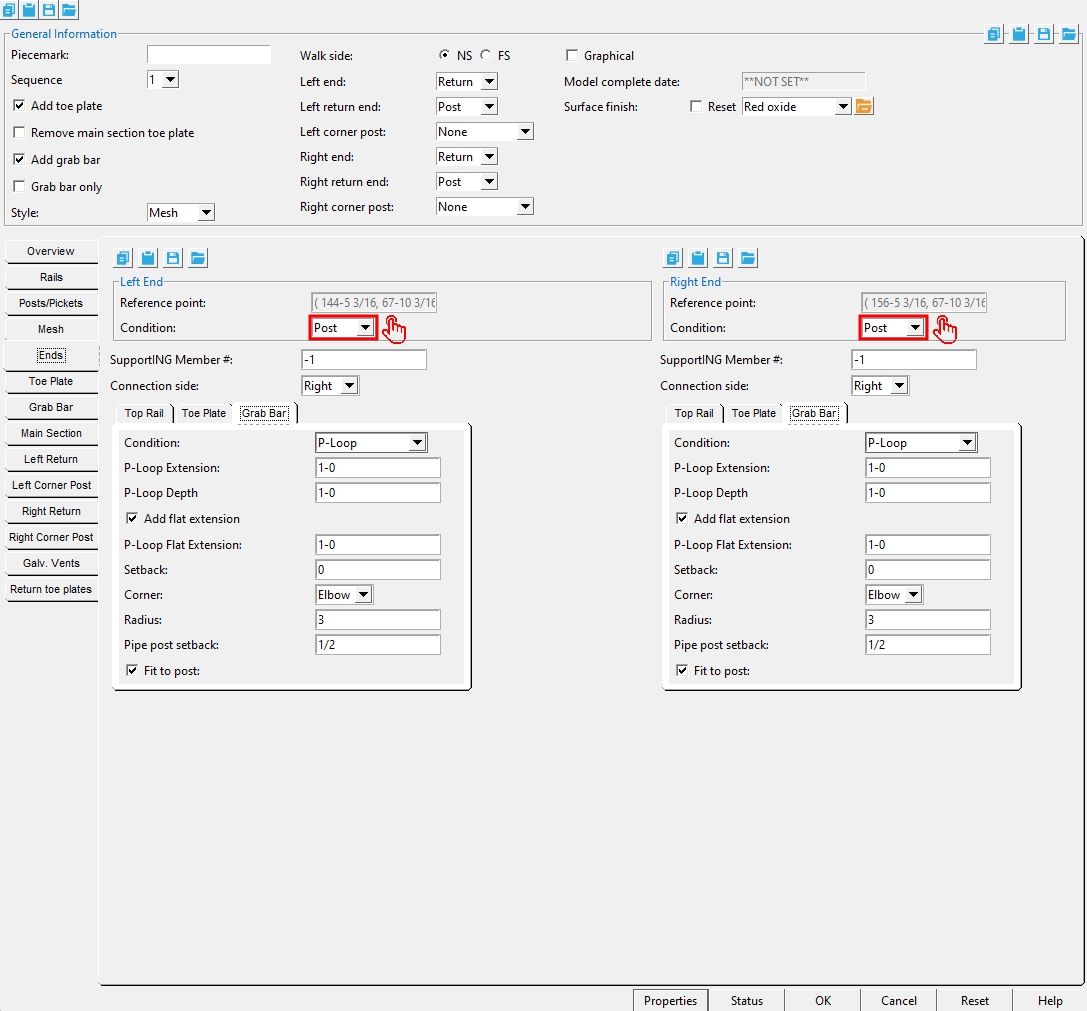
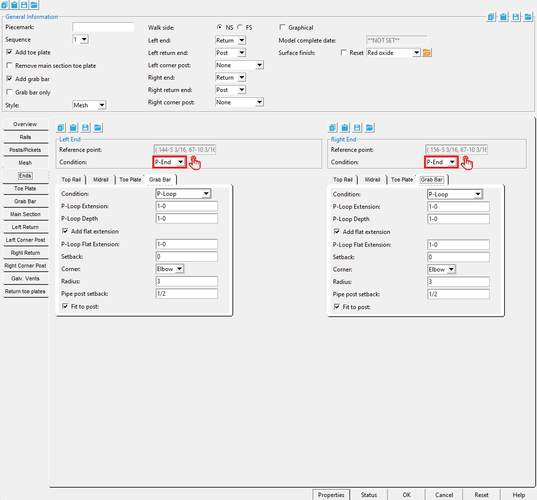
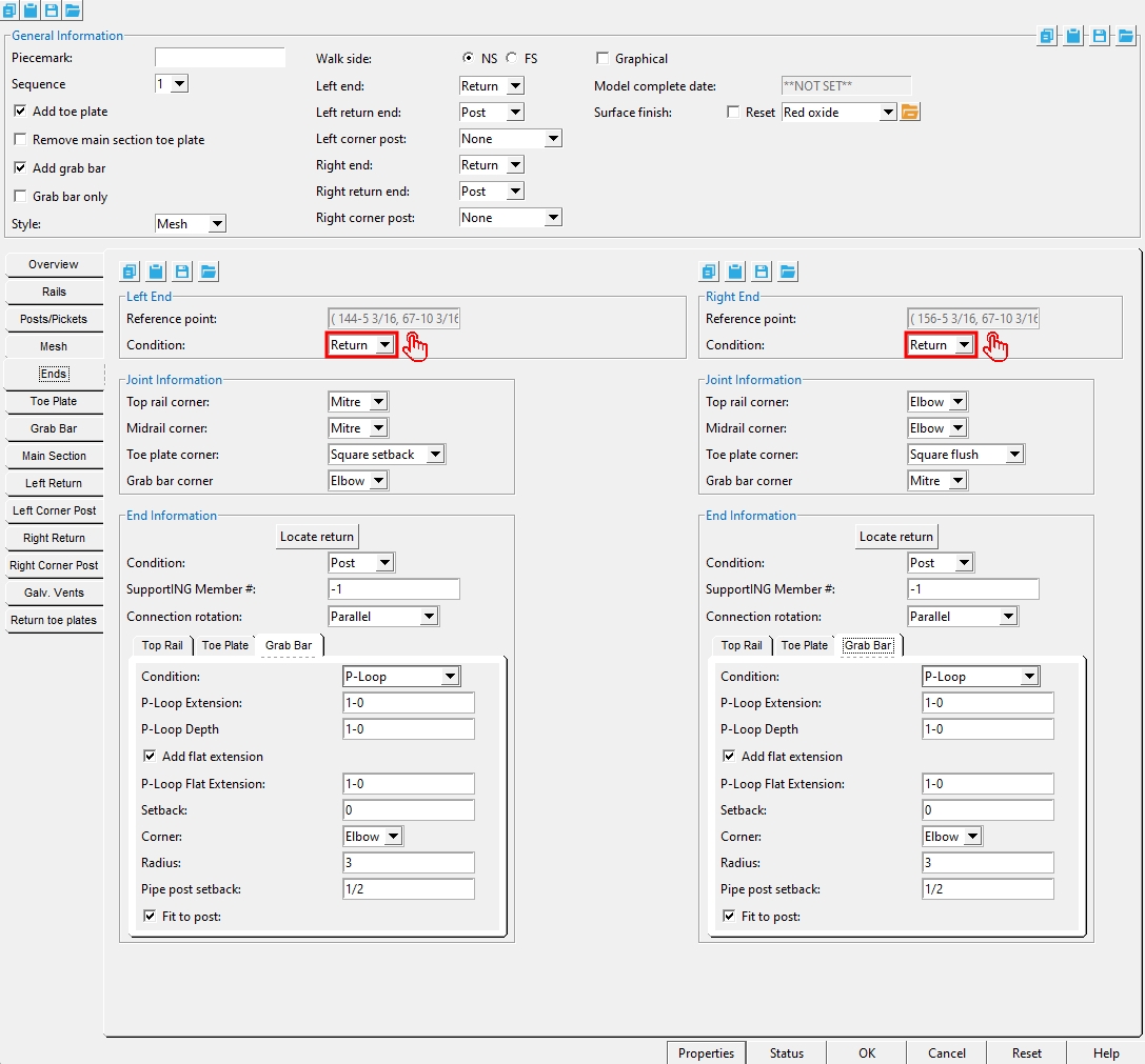
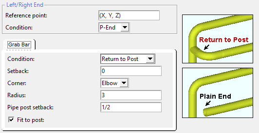
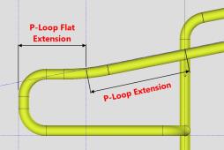
Condition: Plain end or P-Loop or Return to Post .
' Plain end ' should be selected if you want to model an end condition that is not provided.
' P-Loop ' generates a 180 degree extension and return that requires an ' Elbow ' or ' Mitre '.
' Return to Post ' generates a 90 degree return that requires an ' Elbow ' or ' Mitre '.
P-Loop Extension: A positive or negative (-) distance.
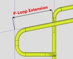
A ' negative (-) distance ' extends the P-Loop past the end post.
A ' positive distance ' backs the P-Loop away from the left-end end post toward the right end.
Note: The work point aligns with the center of a pipe or tube end post.
P-Loop Depth: The distance from the top work point of the P-Loop grab bar to the bottom edge of the P-Loop.
If this box is checked (
If this box is not checked (
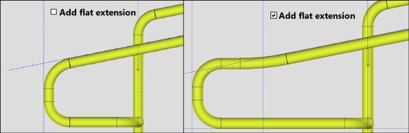
P-Loop Flat Extension: A distance the P-Loop grab bar is extended parallel to the ground past the P-Loop Extension.
Setback: A positive or negative (-) distance.
' - distance '
' 0 (zero) '
' + distance '
A ' negative (-) distance ' extends the grab bar past the end post.
A ' positive distance ' backs the grab bar away from the left-end end post toward the right end.
Note: The work point aligns with the center of a pipe or tube end post if the top rail is the same material.
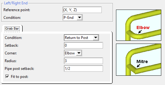
' Elbow ' adds two extra fittings: an end post fitting; an elbow that is the " Radius " specified below.
' Mitre ' adds one extra fitting to connect the end post to the grab bar.
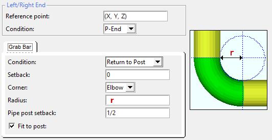
Radius: The radius of the bend of the elbow that is applied when " Corner " is set to ' Elbow ' for a pipe grab bar.
Setback: A positive or negative (-) distance.
| ' - distance '
|
' 0 (zero) '
|
' + distance '
|
A ' negative (-) distance ' extends the grab bar past the end post.
A ' positive distance ' backs the grab bar away from the left-end end post toward the right end.
Note: The work point aligns with the center of a pipe or tube end post if the top rail is the same material.
If this box is checked (
If the box is not checked (
Type: Pipe or Round Bar . " Length " ( len ) is the total length of the splice material. " Stick through " ( ST ) is the distance that the splice sticks out beyond the end of the grab bar.
' Pipe ' requires that you enter a pipe " Section size " to be used as the midrail splices.
' Round Bar ' requires that you enter the " Diameter " of the round bar to be used for the midrail splices.
Section size: Any section size of the specified material type that is in the local shape file . You can type in the section size that you want, or you can press the "file cabinet" browse button ( ![]() ) and double-click any section that is on the list of available materials in the local shape file. Validation only lets you enter a material that is listed in the local shape file.
) and double-click any section that is on the list of available materials in the local shape file. Validation only lets you enter a material that is listed in the local shape file.
Grade: A36 or A572 or etc. The steel grade of the connection material. If the grade of steel that you want is not shown as a menu option ( ![]() ) on the Hand Rail window, you can add the grade you want to the setup table.
) on the Hand Rail window, you can add the grade you want to the setup table.
Length: The connection material length (len). Increasing the " Length " of the connection material adds the extra material toward the inside of the grab bar.
Stick through: The distance that the splice sticks out beyond the end of the grab bar.
Toe Plate Tab
Add:
![]() or
or ![]() . An option to " Add toe plate " is available under " General Information " as well as here. Toe plate options for " Connection " and " Clip top corner " and " Add stabilizer angle " are located under the " Ends " tab.
. An option to " Add toe plate " is available under " General Information " as well as here. Toe plate options for " Connection " and " Clip top corner " and " Add stabilizer angle " are located under the " Ends " tab.
Thickness: The thickness of the toe plate. This is also The " Material thickness " of the rectangular plate material that the toe plate is made of.
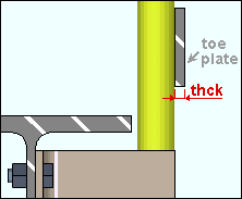
Width: The distance from the top edge of the toe plate to its bottom edge.
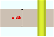
Grade: A36 or A572-42 or etc. The steel grade of the plate material. Steel grades that are available for a particular material depend on the type of grab bar selected. If the grade of steel that you want is not shown as a menu option ( ![]() ) on the Hand Rail window, you can add the grade you want to the setup table.
) on the Hand Rail window, you can add the grade you want to the setup table.
Surface finish: None or Sandblasted or Red oxide or Yellow zinc or Gray oxide or Blued steel or Galvanized or Duplex Coating or Undefined 1 or Undefined 2 or Undefined 3 or Red oxide 2 or Any user added surface finish. This affects the colors of Solid members on erection views in the Drawing Editor . This also sets the color when Output material color is set to Surface finish for a VRML Export or a DWG/DXF Export. The Color (not Surface finish) sets the color of this material in Modeling .
| sand blasted | red oxide | yellow zinc | user surface finish 1 |
| gray oxide | blued steel | galvanized | user surface finish 2 |
To assign a different surface finish, you can drop-down the current surface finish and select the one you want, or you can press the
Auto ![]() or
or ![]()
If this box
If the box
Note 1: Submaterial piecemarks can be split apart by surface finish. All surface finishes that do not have the Break Marks Material checked on can be applied to any like material with out the material splitting. If the Break Marks Material is checked on then only like materials with that specific surface finish can have the same piecemark, and because the submaterial marks differ so would the member's piecemark.
Note 2: When exporting a KISS file using "model" as the Data source surface finish data on the materials are compiled into the KISS download as follows, with a few exceptions (G=galvanized, N= none or sandblasted, P= others). Those exceptions are:
If the box for Finish routing in KISS export setup is set to a user routing
If the user has adjusted the Abbreviation for any of the default provided surface finishes
If you are using a user added surface finish
In these cases you will get what is provided in either the User routing, or the abbreviation field. For other exports it will always provide the abbreviation in the 'surface finishes' settings page.
Tip 1: Surface area is reported on the General Information window -- and this can be used to estimate the amount of coating required and its cost.
Tip 2: Changing Steel grade, Color, and Surface finish do not cause the plate to be regenerated. This means that, if you change those settings only, material fit operations such as a Fit Exact may optionally be preserved.
Report Writer: MemberMaterial.Material.SurfaceFinish
Setup: Surface Finish Settings
Finished floor distance: The actual or vertical distance that the bottom edge of the toe plate is above the " Floor thickness ."
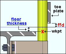
Dimension type: Actual or Vertical . This sets the method for measuring the distance between two parallel reference lines.
|
If the handrail slopes, ' Actual ' sets the dimension to be the shortest distance (a perpendicular) between the two lines. ' Vertical ' sets the dimension to be measured vertically. For a non-sloping handrail, both ' Actual ' and ' Vertical ' are perpendicular to the two parallel lines. |
Post connection: Field (field bolted) or Shop (shop bolted) or Weld . This applies when the post " Type " is ' Pipe ' or ' Tube ' or ' Angle '.
' Shop ' shop bolts the posts to the toe plate. For pipe or tube posts, angle brackets are used. The toe plate and shop bolts appear on the handrail detail and, in the model, the toe plate remains associated with the handrail member.
' Field ' field bolts the posts to the toe plate. For pipe or tube posts, angle brackets are used. The toe plate is broken off from the handrail member and becomes its own legacy miscellaneous member .
' Weld ' designates that the toe plate be welded to the member. No welds are generated in the model or on the handrail detail.
Stabilizer finish: None or Sandblasted or Red oxide or Yellow zinc or Gray oxide or Blued steel or Galvanized or Duplex Coating or Undefined 1 or Undefined 2 or Undefined 3 or Red oxide 2 or Any user added surface finish. This affects the colors of 'Solid ' members on erection views in the Drawing Editor . This also sets the color when "Output material color " is set to 'Surface finish ' for a VRML Export or a DWG/DXF Export . The "Color " ( not "Surface finish ") sets the color of this material in Modeling .
| sand blasted | red oxide | yellow zinc | user surface finish 1 |
| gray oxide | blued steel | galvanized | user surface finish 2 |
To assign a different surface finish, you can drop-down the current surface finish and select the one you want, or you can press the "file cabinet" browse button (
Auto ![]() or
or ![]() .
.
If this box is checked (
If the box is not checked (
Note 1:Submaterial piecemarkscan be split apart by surface finish. All surface finishes that do not have the 'Break Marks Material' checked on can be applied to any like material with out the material splitting. If the 'Break Marks Material' is checked on then only like materials with that specific surface finish can have the same piecemark, and because the submaterial marks differ so would the member's piecemark.
Note 2:When exporting a KISS file using "model" as the "Data source " surface finish data on the materials are compiled into the KISS download as follows, with a few exceptions (G=galvanized, N= none or sandblasted, P= others). Those exceptions are:
If the box for "Finish" routing in KISS export setup is set to a user routing
If the user has adjusted the Abbreviation for any of the default provided surface finishes
If you are using a user added surface finish
In these cases you will get what is provided in either the User routing, or the abbreviation field. For other exports it will always provide the abbreviation in the 'surface finishes' settings page.
Tip 1: "Surface area" is reported on the General Information window -- and this can be used to estimate the amount of coating required and its cost.
Tip 2: Changing "Steel grade " "Color " and "Surface finish " do not cause the plate to be regenerated. This means that, if you change those settings only, material fit operations such as a Fit Exact may, optionally, be preserved.
Report Writer: MemberMaterial.Material.SurfaceFinish
Setup: Surface Finish Settings
------ Hole information ------
Gage: The distance from the heel of the angle post to the column of holes for bolting the post to the toe plate. This applies when the post " Type " is ' Angle ' and the " Post connection " is ' Shop ' or ' Field '.
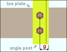
Edge distance: The distance from the top of the toe plate to the center of the first hole for bolting to the toe plate. This applies when the post " Type " is ' Angle ' or ' Pipe ' or ' Tube ' and the " Post connection " is ' Shop ' or ' Field '.
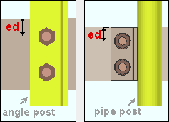
Rows: The number (a count) of holes for bolting the toe plate to a post. Brackets are used for a pipe or tube post. This applies when the post " Type " is ' Angle ' or ' Pipe ' or ' Tube ' and the " Post connection " is ' Shop ' or ' Field '.
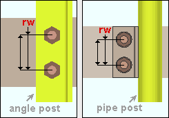
Row spacing: The distance between adjacent rows of holes in column of holes for bolting the toe plate to the handrail post. This applies when the post " Type " is ' Angle ' or ' Pipe ' or ' Tube ' and the " Post connection " is ' Shop ' or ' Field '.
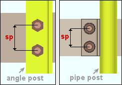
Type: Standard round or Short slot or PIP slot or Oversized round or Long slot . The " Hole type " to be used in the toe plate.

Matching holes will be generated in the post connection so that the connection material can be bolted to that member. The matching holes in the support will be standard round even if " Short slot " or " Long slot " or " Oversized " is used.
Setup: Hand Rail Setup ( Home > Project Settings > Job > Plugin Defaults... )
Rotation: A positive or negative value from 90 to -90 degrees. This is also the " Slot rotation " of the hole on its edit window. This slot rotation applies only when the hole " Type " is ' Long slot ' or ' Short slot '. Slot rotations can be modeled to a precision of 0.1 degree.
| when material X axis (length)
is horizontal (<==>) |
when material X axis (length)
is vertical |
' 0 ' (zero) degrees sets the length of the slot parallel to the material X axis . Since an angle post has a X material axis that is vertical, the orientation of the slot would also be vertical.
A ' positive number ' of degrees rotates the slot counterclockwise.
A ' negative number ' of degrees rotates the slot clockwise.
Exceptions: The rule that ' 0 ' sets the slot rotation to be parallel with the length of the material works for handrail, but does not apply to other member types. For other member types, the hole group X axis follows the member's length, not the material's length. Also, this rule does not work for holes that are generated on the support since these holes are created by matching from the connection material on the handrail.
Setup: Hand Rail Setup ( Home > Project Settings > Job > Plugin Defaults... )
Bolt Diameter: The diameter of the shank of the bolt. This is also the " Diameter " of the bolt on its edit window.
| diameter |
|
The hole in the handrail that the bolt is inserted through is sized based on the bolt's " Diameter " and the " Type " of that hole.
Setup: Hand Rail Setup ( Home > Project Settings > Plugin Defaults... )
Type: A307 or etc. The " Bolt type " of the bolt.
Note: Since handrail members do not undergo connection design , the Hand Rail program does not check to see if the bolt " Type " or the
" Diameter " that you enter will stand up to loading conditions. It is your responsibility to ensure that the required design calculations are made.Setup: If the bolt type that you want does not appear as a selectable option (
), you may add it in to the menu for this field by using Home > Project Settings > Job > Bolts, Washers, and Holes > Bolt Specifications .
Setup: Hand Rail Setup ( Home > Project Settings > Job > Plugin Defaults... )
------ Bracket information ------
Section size: Any section size of the specified material type that is in the local shape file . You can type in the section size that you want, or you can press the "file cabinet" browse button ( ![]() ) and double-click any section that is on the list of available materials in the local shape file. Validation only lets you enter a material that is listed in the local shape file.
) and double-click any section that is on the list of available materials in the local shape file. Validation only lets you enter a material that is listed in the local shape file.
Long leg to: Supported or Supporting. This applies when the " Section size " for a pipe or tube post angle bracket used to support a toe plate is an angle with unequal legs.
' Supported ' puts the long leg of the bracket to the toe plate.
' Supporting ' puts the long leg of the bracket to the post.
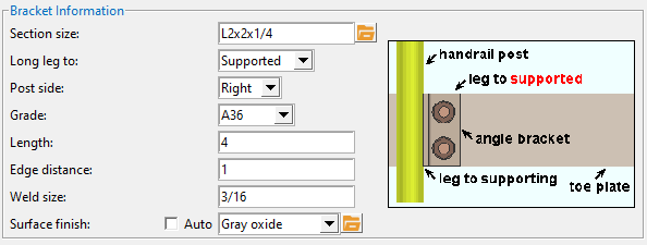
' Left ' places the bracket so that the post is to its left.
' Right ' places the bracket so that the post is to its right.
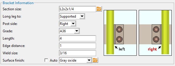
Grade: A36 or A572 or etc. The steel grade of the material. If the grade of steel that you want is not shown as a menu option ( ![]() ) on the Hand Rail window, you can add the grade you want to the setup table.
) on the Hand Rail window, you can add the grade you want to the setup table.
Length: The distance from the top edge of the angle bracket to its bottom edge. Posts are always perfectly vertical, so this will always be a vertical dimension.
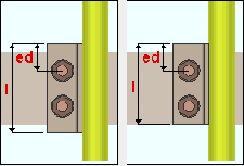
Edge distance: The distance from the top edge of the angle bracket to the center of the top hole in the bracket. Changing the " Edge distance " does not change the hole (or bolt) position in the bracket -- it repositions the bracket.
Also see: The position of the top hole in the bracket matches the top hole in the toe plate and is set per the " Edge distance " under " Hole information ."
Weld size: The weld size of the fillet weld used to shop weld the bracket to the post. This applies when the post " Type " is ' Tube ' and the " Post connection " is
Surface finish: None or Sandblasted or Red oxide or Yellow zinc or Gray oxide or Blued steel or Galvanized or Duplex Coating or Undefined 1 or Undefined 2 or Undefined 3 or Red oxide 2 or Any user added surface finish. This affects the colors of Solid members on erection views in the Drawing Editor . This also sets the color when Output material color is set to Surface finish for a VRML Export or a DWG/DXF Export. The Color (not Surface finish) sets the color of this material in Modeling .
| sand blasted | red oxide | yellow zinc | user surface finish 1 |
| gray oxide | blued steel | galvanized | user surface finish 2 |
To assign a different surface finish, you can drop-down the current surface finish and select the one you want, or you can press the
Auto ![]() or
or ![]()
If this box
If the box
Note 1: Submaterial piecemarks can be split apart by surface finish. All surface finishes that do not have the Break Marks Material checked on can be applied to any like material with out the material splitting. If the Break Marks Material is checked on then only like materials with that specific surface finish can have the same piecemark, and because the submaterial marks differ so would the member's piecemark.
Note 2: When exporting a KISS file using "model" as the Data source surface finish data on the materials are compiled into the KISS download as follows, with a few exceptions (G=galvanized, N= none or sandblasted, P= others). Those exceptions are:
If the box for Finish routing in KISS export setup is set to a user routing
If the user has adjusted the Abbreviation for any of the default provided surface finishes
If you are using a user added surface finish
In these cases you will get what is provided in either the User routing, or the abbreviation field. For other exports it will always provide the abbreviation in the 'surface finishes' settings page.
Tip 1: Surface area is reported on the General Information window -- and this can be used to estimate the amount of coating required and its cost.
Tip 2: Changing Steel grade, Color, and Surface finish do not cause the plate to be regenerated. This means that, if you change those settings only, material fit operations such as a Fit Exact may optionally be preserved.
Report Writer: MemberMaterial.Material.SurfaceFinish
Setup: Surface Finish Settings
Grab Bar Tab
Add:
![]() or
or ![]() . Same as " Add grab bar " under General Information . The side (' NS ' or ' FS ') of the toe plate is set using " Walk side ." This option is disabled (grayed out) when the post " Type " is ' Angle '.
. Same as " Add grab bar " under General Information . The side (' NS ' or ' FS ') of the toe plate is set using " Walk side ." This option is disabled (grayed out) when the post " Type " is ' Angle '.
Type: Pipe ( HSS round ) or Tube ( HSS rectangular ). Note that the top rail " Reference line " does not matter for grab bar " Vertical distance " or " Horizontal distance " measure -- these are measured to the center of the top rail.
Surface finish: None or Sandblasted or Red oxide or Yellow zinc or Gray oxide or Blued steel or Galvanized or Duplex Coating or Undefined 1 or Undefined 2 or Undefined 3 or Red oxide 2 or Any user added surface finish. This affects the colors of Solid members on erection views in the Drawing Editor . This also sets the color when Output material color is set to Surface finish for a VRML Export or a DWG/DXF Export. The Color (not Surface finish) sets the color of this material in Modeling .
| sand blasted | red oxide | yellow zinc | user surface finish 1 |
| gray oxide | blued steel | galvanized | user surface finish 2 |
To assign a different surface finish, you can drop-down the current surface finish and select the one you want, or you can press the
Auto ![]() or
or ![]()
If this box
If the box
Note 1: Submaterial piecemarks can be split apart by surface finish. All surface finishes that do not have the Break Marks Material checked on can be applied to any like material with out the material splitting. If the Break Marks Material is checked on then only like materials with that specific surface finish can have the same piecemark, and because the submaterial marks differ so would the member's piecemark.
Note 2: When exporting a KISS file using "model" as the Data source surface finish data on the materials are compiled into the KISS download as follows, with a few exceptions (G=galvanized, N= none or sandblasted, P= others). Those exceptions are:
If the box for Finish routing in KISS export setup is set to a user routing
If the user has adjusted the Abbreviation for any of the default provided surface finishes
If you are using a user added surface finish
In these cases you will get what is provided in either the User routing, or the abbreviation field. For other exports it will always provide the abbreviation in the 'surface finishes' settings page.
Tip 1: Surface area is reported on the General Information window -- and this can be used to estimate the amount of coating required and its cost.
Tip 2: Changing Steel grade, Color, and Surface finish do not cause the plate to be regenerated. This means that, if you change those settings only, material fit operations such as a Fit Exact may optionally be preserved.
Report Writer: MemberMaterial.Material.SurfaceFinish
Setup: Surface Finish Settings
Section size: Any section size of pipe or tube that is in the local shape file . You can type in the section size that you want, or you can press the "file cabinet" browse button ( ![]() ) and double-click any section that is on the list of available materials in the local shape file. Validation only lets you enter a material that is listed in the local shape file.
) and double-click any section that is on the list of available materials in the local shape file. Validation only lets you enter a material that is listed in the local shape file.
Long side direction: Vertical or Horizontal . This applies when the " Section size " for the tube grab bar is a rectangular (non-square) HSS/TS section.
' Vertical ' orients the tube grab bar vertically.
' Horizontal ' orients the tube grab bar horizontally.
Grade: A53 or A500C or etc. The steel grade of the pipe or tube material. Steel grades that are available for a particular material depend on the type of grab bar selected. If the grade of steel that you want is not shown as a menu option ( ![]() ) on the Hand Rail window, you can add the grade you want to the setup table.
) on the Hand Rail window, you can add the grade you want to the setup table.
Bend radius: This applies to the bend in a pipe grab bar when the handrail's end " Condition " is ' Return '. Increasing the bend radius increases the elbow's
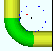
Related settings: A bend " Radius " can also be set when the grab bar's end is set to ' Return to post '.
Vertical distance: The actual or vertical distance from the center of the top rail to the center of the grab bar. The " Vertical distance " is always measured from the center of the pipe or tube top rail, regardless of what the " Reference line " is set to.
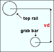
Dimension type: Actual or Vertical . This affects how the " Vertical distance " that is entered above is applied when positioning the grab bar.
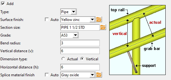
|
The ' Actual ' distance is measured perpendicular to the top rail and the grab bar. The ' Vertical ' distance is measured vertical to the world. |
Horizontal distance: The distance from the center of the top rail to the center of the grab bar. The " Horizontal distance " is always measured from the center of the pipe or tube top rail, regardless of what the " Reference line " is set to. Consequently, if the handrail slopes, this is a sloped (non-horizontal) dimension.
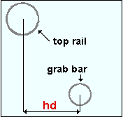
Splice Material Finish: The surface finish for the splicing materials.
------ Supports ------
Add:
![]() or
or ![]() . If this box is checked (
. If this box is checked ( ![]() ), grab bar supports of the specified diameter connect each intermediary post to the grab bar. The supports are made of round bar material.
), grab bar supports of the specified diameter connect each intermediary post to the grab bar. The supports are made of round bar material.
Section Size: any round bar " Section size " that is maintained in the local shape file.
Centerline bend radius: A distance that defines the sharpness of the bend in the grab bar support. A smaller distance bends the support more sharply. Larger distances give you a more gradual bend.
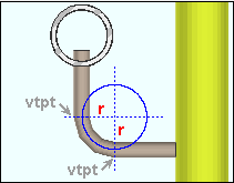
Vertical offset: The distance from the centerline of the support where it interfaces with the post to where the support interfaces with the grab bar. " Vertical offset " is an actual dimension -- it is a vertical dimension (as shown) only if the handrail is horizontal.
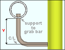
Grab bar penetration: The distance from where the support interfaces with the grab bar to the top end of the support. Enter 0 (zero) if you want the support to go flush to the grab bar, without penetrating it.
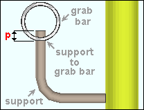
Orient relative to: Post or Rail . This applies to handrails that slope.
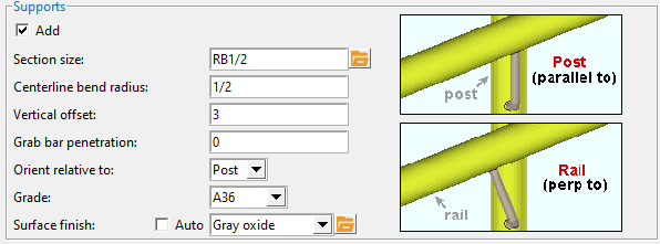
' Post ' orients the grab bar support bar parallel with the post that it welds to. Since posts are vertical, the support will be aligned vertically.
' Rail ' orients the grab bar support bar perpendicular to the grab bar that it welds to.
Grade: A36 or A572-42 or etc. The steel grade of the pipe or tube material. Steel grades that are available for a particular material depend on the type of grab bar selected. If the grade of steel that you want is not shown as a menu option ( ![]() ) on the Hand Rail window, you can add the grade you want to the setup table.
) on the Hand Rail window, you can add the grade you want to the setup table.
Surface Finish: The surface finish for the support materials.
Main Section Tab
Section length: plan The read-only horizontal distance between the section ends; that is, the distance between them in plan view.
Section length: actual The read-only actual distance between the section ends, measured along the slope of the section. If the section is perfectly horizontal, this distance will be the same as the " Section length: plan ."
Floor thickness: The actual distance that the finished floor is above the work points established when the hand rail was added .
Closure Plate
Add:
![]() or
or ![]() . This applies to all intermediate and end posts whose " Type " is ' Pipe ' or ' Tube '.
. This applies to all intermediate and end posts whose " Type " is ' Pipe ' or ' Tube '.
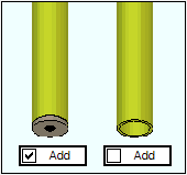
If this box is checked (
If the box is not checked (
Thickness: The thickness of the closure plate. For a rectangular closure plate (on a tube post), this is the rectangular plate " Material thickness ." For a round closure plate (on a pipe post), this is the round plate " Material thickness ."
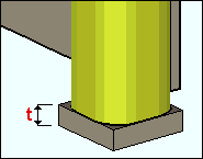
Grade: A36 or A572 or etc. The steel grade of the material.
Surface finish: None or Sandblasted or Red oxide or Yellow zinc or Gray oxide or Blued steel or Galvanized or Duplex Coating or Undefined 1 or Undefined 2 or Undefined 3 or Red oxide 2 or Any user added surface finish. This affects the colors of Solid members on erection views in the Drawing Editor . This also sets the color when Output material color is set to Surface finish for a VRML Export or a DWG/DXF Export. The Color (not Surface finish) sets the color of this material in Modeling .
| sand blasted | red oxide | yellow zinc | user surface finish 1 |
| gray oxide | blued steel | galvanized | user surface finish 2 |
To assign a different surface finish, you can drop-down the current surface finish and select the one you want, or you can press the
Auto ![]() or
or ![]()
If this box
If the box
Note 1: Submaterial piecemarks can be split apart by surface finish. All surface finishes that do not have the Break Marks Material checked on can be applied to any like material with out the material splitting. If the Break Marks Material is checked on then only like materials with that specific surface finish can have the same piecemark, and because the submaterial marks differ so would the member's piecemark.
Note 2: When exporting a KISS file using "model" as the Data source surface finish data on the materials are compiled into the KISS download as follows, with a few exceptions (G=galvanized, N= none or sandblasted, P= others). Those exceptions are:
If the box for Finish routing in KISS export setup is set to a user routing
If the user has adjusted the Abbreviation for any of the default provided surface finishes
If you are using a user added surface finish
In these cases you will get what is provided in either the User routing, or the abbreviation field. For other exports it will always provide the abbreviation in the 'surface finishes' settings page.
Tip 1: Surface area is reported on the General Information window -- and this can be used to estimate the amount of coating required and its cost.
Tip 2: Changing Steel grade, Color, and Surface finish do not cause the plate to be regenerated. This means that, if you change those settings only, material fit operations such as a Fit Exact may optionally be preserved.
Report Writer: MemberMaterial.Material.SurfaceFinish
Setup: Surface Finish Settings
Add drain hole:
![]() or
or ![]() . This applies when the closure plate is on a pipe (shown) or on a tube (not shown).
. This applies when the closure plate is on a pipe (shown) or on a tube (not shown).
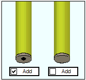
If this box is checked (
If the box is not checked (
Diameter: The diameter of the drain hole.
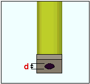
Intermediate Posts
Post Spacing Method: Auto or Semi Auto or User or Semi User . Spacing between pipe and tube posts is measured center to center. Spacing between pipe posts is measured heel to heel.
Auto: instructs the Hand Rail program to first calculate the minimum number of posts that can be spaced less than the " Maximum spacing " apart from one another. Hand Rail then determines the number of spaces between posts. Hand Rail then divides the total distance between the end posts by the number of spaces to determine the spacing between posts.
Maximum Spacing: A maximum distance applied to the spacing between all of the posts in the main section, including the end posts.
Round Up: If a value other than zero is entered here, the Hand Rail program rounds up the " Left End Distance " to the next increment of the round up value.
Semi Auto: lets you enter a " Left end to 1st intermediate " and a " Right end to 1st intermediate " distance to set the exact spacing from the outside (end) posts to the intermediate posts nearest to them. The Hand Rail program then uses the " Maximum spacing " to determine the spacing between any posts that are between these outside posts.
Max left end to 1st intermediate: A maximum distance to set the exact spacing from the outside (end) posts to the first intermediate post from the left end.
Max right end to 1st intermediate: A maximum distance to set the exact spacing from the outside (end) posts to the first intermediate post from the right end.
Maximum Spacing: A maximum distance applied to the spacing between the intermediate posts only.
Round up:If a value other than zero is entered here, the Hand Rail program rounds up the " Left End Distance " to the next increment of the round up value.
User: lets you specify exactly in the model where you want the intermediate posts located.
Post count: The total number of intermediate posts that you want between the two end posts.
Locate : Hand Rail add window closes and provides you Locate- Pan -Return mouse bindings for locating points on the workline of the handrail where you want the posts.
Left end to 1st intermediate: A distance to set the exact spacing from the outside (end) posts to the first intermediate post from the left end.
Right end to 1st intermediate: A distance to set the exact spacing from the outside (end) posts to the first intermediate post from the right end.
Maximum spacing: A maximum distance applied to the spacing between the intermediate posts only.
Toe direction: Right or Left . This applies when the " Type " of post is ' Angle '.
Connection side: Left or Center or Right . This applies when the " Type " of post is ' Pipe ' or ' Tube ' and the " Type " of connection is ' Bent Plate ' or ' Clip angle ' or ' Shear Tab ' or ' W Tee '.
|
' Center ' is only for ' Shear Tab ' or ' W Tee '. It is your responsibility to size your connection materials to prevent material clashes -- the Hand Rail program does not size the materials for you.
The Intermediate post table has a row for each intermediate post, with the leftmost intermediate post listed in the first row. You can click in a cell on the table to directly edit the value that is reported in that cell. For example, you can use this table to change how the posts are spaced. When you press " OK " (so that Create Solids is performed on the handrail), the support will also undergoes Create Solids to ensure that matching holes are properly placed in it. If you delete the handrail, the support is either marked for Create Solids or it automatically undergoes Create Solids .
|
|||||||||||||||
| ' 3-8 ' is the distance from the left-end post to the nearest intermediate post, ' 7-4 ' is to the next-nearest post. | ' -1 ' is the member that the post connects to. | ' Right ' is the direction that the toe of the angle post points. | ' Left ' is the side of the post that the connection is on. | ||||||||||||
Corner Post Tab
Corner post: None or Main section or Return . Same as " Left corner post " under the General Information section; setting it here also sets it there.
SupportING member #: This is the member that the post connects to. Typically, Hand Rail tool attaches the post to the nearest member if possible, and user intervention is not required. However, if there is more than one proximate member (for example, if the post connection rests on a spliced beam), you may enter another member number if desired. If the member number is negative ('-1'), no nearby member was found by the Hand Rail tool to attach the post to.
Angle post toe direction: Read only . This applies when the " Connection " of the post is an angle. This is the direction that the toe of the angle post points.
Connection: That is, the " Type " of connection, the same as those of " Main Section :" Angle Bracket or Base Plate or Bent Plate or Bolted (Angle) or Clip Angle or Continuous Bottom Plate or L Shaped Plate or Plain End or Rectangular Plate or Shear Tab or Shear Tab (Angle) or Welded or W Tee .
Galv. Vents Tab
External vent hole weld clearance: The distance that the edge of the hole must be, at minimum, from the nearest intersecting material.
------ Ends ------
Elbow vent hole diameter: This applies when the " Left end " or " Right end " is a ' P-End ' or a ' Post '. Per American Galvanizers Association guidelines, vent holes in end sections are set, by default, to 1/2 inch (13 mm), and when " ![]() Add external vent holes on end post elbow " is checked.
Add external vent holes on end post elbow " is checked.
Add external vent holes on end post elbow: ![]() or
or ![]() . This applies when the " Left end " or the " Right end " is a ' Post ', the top rail " Type " is a ' Pipe '.
. This applies when the " Left end " or the " Right end " is a ' Post ', the top rail " Type " is a ' Pipe '.
If this box is checked (
If this box is not checked (
P-End vent holes: None or In Elbow or In Rail . This applies when the " Left end " or the " Right end " is a ' P-End '," and the top or midrail " Type " is ' Pipe '.
'None'
|
'In Elbow'
|
' In Rail '
|
------ Post ------
Internal:
![]() or
or ![]() . This option is for internal galvanizing vents for posts , midrails , pickets/mesh , grab bars .
. This option is for internal galvanizing vents for posts , midrails , pickets/mesh , grab bars .
|
|
If this box is checked (
Internal in Connection Plates "
If this box is not checked (
Setup: Hand Rail Setup ( Home > Project Settings > Job > Plugin Defaults... )
Internal in Connection Plates: ![]() or
or ![]() . This option is for internal galvanizing vents at post connection material when that connection" Type " is ' Continuous Bottom Plate , ' Base Plate ' or ' L Shaped Plate .'
. This option is for internal galvanizing vents at post connection material when that connection" Type " is ' Continuous Bottom Plate , ' Base Plate ' or ' L Shaped Plate .'
|
|
If this box is checked (
Internal " is unchecked.
If this box is not checked (
Auto interior hole diameter: ![]() or
or ![]() . This applies when " Internal " and/or " Internal in Connection Plates " is checked. This option is for setting the diameter of the internal galvanizing holes for posts , midrails , pickets/mesh , grab bars .
. This applies when " Internal " and/or " Internal in Connection Plates " is checked. This option is for setting the diameter of the internal galvanizing holes for posts , midrails , pickets/mesh , grab bars .
If this box is checked (
If this box is not checked (
Setup: Hand Rail Setup ( Home > Project Settings > Job > Plugin Defaults... )
Interior hole diameter: The diameter ) of the internal vent holes for posts , midrails , pickets/mesh , grab bars . This applies when " Internal " and/or Internal in Connection Plates "![]() Auto interior hole diameter " is not checked.
Auto interior hole diameter " is not checked.
Setup: Hand Rail Setup ( Home > Project Settings > Job > Plugin Defaults... )
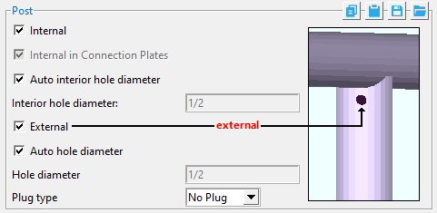
If this box is checked (
If this box is not checked (
Auto hole diameter: ![]() or
or ![]() . This option is for setting the diameter of the external vent holes for posts , top rails , midrails , pickets/mesh , grab bars .
. This option is for setting the diameter of the external vent holes for posts , top rails , midrails , pickets/mesh , grab bars .
If this box is checked (
If this box is not checked (
Setup: Hand Rail Setup ( Home > Project Settings > Job > Plugin Defaults... )
Hole diameter: The diameter of the external vent holes for posts , top rails , midrails , pickets/mesh , grab bars . It applies when " ![]() Auto hole diameter " is not checked. On the Hole Edit window, this diameter is reported as the " Hole diameter ."
Auto hole diameter " is not checked. On the Hole Edit window, this diameter is reported as the " Hole diameter ."
Setup: Hand Rail Setup ( Home > Project Settings > Job > Plugin Defaults... )
Plug type:No Plug or Zinc Plug or Plug Weld or Aluminum or Epoxy . This is the " Plug type " of the external vent hole.
Setup: Hand Rail Setup ( Home > Project Settings > Job > Plugin Defaults... )
------ Top rail ------
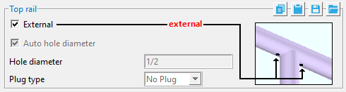
|
If this box is checked ( If this box is not checked ( |
Auto hole diameter:
If this box is checked (
If this box is not checked (
Setup: Hand Rail Setup ( Home > Project Settings > Job > Plugin Defaults... )
Hole diameter: The diameter of the external vent holes for posts , top rails , midrails , pickets/mesh , grab bars . It applies when
" is not checked. On the Hole Edit window, this diameter is reported as the " Hole diameter ."Setup: Hand Rail Setup ( Home > Project Settings > Job > Plugin Defaults... )
Plug type:No Plug or Zinc Plug or Plug Weld or Aluminum or Epoxy . This is the " Plug type " of the external vent hole.
Setup: Hand Rail Setup ( Home > Project Settings > Job > Plugin Defaults... )
------ Midrail ------
Internal:
If this box is checked (
If this box is not checked (
Setup: Hand Rail Setup ( Home > Project Settings > Job > Plugin Defaults... )
Auto interior hole diameter:
If this box is checked (
If this box is not checked (
Setup: Hand Rail Setup ( Home > Project Settings > Job > Plugin Defaults... )
Interior hole diameter: The diameter of the internal vent holes for posts , midrails , pickets/mesh , grab bars . This applies when
" and/or "Setup: Hand Rail Setup ( Home > Project Settings > Job > Plugin Defaults... )
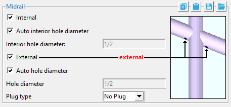
If this box is checked (
If this box is not checked (
Auto hole diameter:
If this box is checked (
If this box is not checked (
Setup: Hand Rail Setup ( Home > Project Settings > Job > Plugin Defaults... )
Hole diameter: The diameter of the external vent holes for posts , top rails , midrails , pickets/mesh , grab bars . It applies when
" is not checked. On the Hole Edit window, this diameter is reported as the " Hole diameter ."Setup: Hand Rail Setup ( Home > Project Settings > Job > Plugin Defaults... )
Plug type:No Plug or Zinc Plug or Plug Weld or Aluminum or Epoxy . This is the " Plug type " of the external vent hole.
Setup: Hand Rail Setup ( Home > Project Settings > Job > Plugin Defaults... )
------ Pickets/Mesh ------
Internal:
![]() or
or ![]() . This option is for internal galvanizing vents for posts , midrails , pickets/mesh , grab bars .
. This option is for internal galvanizing vents for posts , midrails , pickets/mesh , grab bars .
|
|
If this box is checked (
If this box is not checked (
Setup: Hand Rail Setup ( Home > Project Settings > Job > Plugin Defaults... )
Auto interior hole diameter: ![]() or
or ![]() . This applies when " Internal " and/or " Internal in Connection Plates " is checked. This option is for setting the diameter of the internal galvanizing holes for posts , midrails , pickets/mesh , grab bars .
. This applies when " Internal " and/or " Internal in Connection Plates " is checked. This option is for setting the diameter of the internal galvanizing holes for posts , midrails , pickets/mesh , grab bars .
If this box is checked (
If this box is not checked (
Setup:Hand Rail Setup ( Home > Project Settings > Job > Plugin Defaults... )
Interior hole diameter: The diameter of the internal vent holes for posts , midrails , pickets/mesh , grab bars . This applies when " Internal " and/or Internal in Connection Plates "![]() Auto interior hole diameter " is not checked.
Auto interior hole diameter " is not checked.
Setup: Hand Rail Setup ( Home > Project Settings > Job > Plugin Defaults... )
External: ![]() or
or ![]() .
.
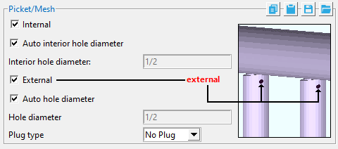
If this box is checked (
If this box is not checked (
The picket " Type " must be ' Pipe ' or ' Tube ' to get external venting. For mesh, venting is applied to the " Vertical support ."
Auto hole diameter: ![]() or
or ![]() . This option is for setting the diameter of the external vent holes for posts , top rails , midrails , pickets/mesh , grab bars .
. This option is for setting the diameter of the external vent holes for posts , top rails , midrails , pickets/mesh , grab bars .
If this box is checked (
If this box is not checked (
Setup: Hand Rail Setup ( Home > Project Settings > Job > Plugin Defaults... )
Hole diameter: The diameter of the external vent holes for posts , top rails , midrails , pickets/mesh , grab bars . It applies when " ![]() Auto hole diameter " is not checked. On the Hole Edit window, this diameter is reported as the " Hole diameter ."
Auto hole diameter " is not checked. On the Hole Edit window, this diameter is reported as the " Hole diameter ."
Setup: Hand Rail Setup ( Home > Project Settings > Job > Plugin Defaults... )
Plug type:No Plug or Zinc Plug or Plug Weld or Aluminum or Epoxy . This is the " Plug type " of the external vent hole.
Setup: Hand Rail Setup ( Home > Project Settings > Job > Plugin Defaults... )
------ Grab Bar ------
Internal:
![]() or
or ![]() . This option is for internal galvanizing vents for posts , midrails , pickets/mesh , grab bars .
. This option is for internal galvanizing vents for posts , midrails , pickets/mesh , grab bars .
|
|
If this box is checked (
If this box is not checked (
Setup: Hand Rail Setup ( Home > Project Settings > Job > Plugin Defaults... )
Auto interior hole diameter: ![]() or
or ![]() . This applies when " Internal " and/or " Internal in Connection Plates " is checked. This option is for setting the diameter of the internal galvanizing holes for posts , midrails , pickets/mesh , grab bars .
. This applies when " Internal " and/or " Internal in Connection Plates " is checked. This option is for setting the diameter of the internal galvanizing holes for posts , midrails , pickets/mesh , grab bars .
If this box is checked (
If this box is not checked (
Setup: Hand Rail Setup ( Home > Project Settings > Job > Plugin Defaults... )
Interior hole diameter: The diameter of the internal vent holes for posts , midrails , pickets/mesh , grab bars . This applies when " Internal " and/or Internal in Connection Plates "![]() Auto interior hole diameter " is not checked.
Auto interior hole diameter " is not checked.
Setup: Hand Rail Setup ( Home > Project Settings > Job > Plugin Defaults... )
External: ![]() or
or ![]() .
.
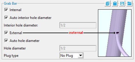
If this box is checked (
If this box is not checked (
Auto hole diameter: ![]() or
or ![]() . This option is for setting the diameter of the external vent holes for posts , top rails , midrails , pickets/mesh , grab bars .
. This option is for setting the diameter of the external vent holes for posts , top rails , midrails , pickets/mesh , grab bars .
If this box is checked (
If this box is not checked (
Setup:Hand Rail Setup ( Home > Project Settings > Job > Plugin Defaults... )
Hole diameter: The diameter of the external vent holes for posts , top rails , midrails , pickets/mesh , grab bars . It applies when " ![]() Auto hole diameter " is not checked. On the Hole Edit window, this diameter is reported as the " Hole diameter ."
Auto hole diameter " is not checked. On the Hole Edit window, this diameter is reported as the " Hole diameter ."
Setup: Hand Rail Setup ( Home > Project Settings > Job > Plugin Defaults... )
Plug type: No Plug or Zinc Plug or Plug Weld or Aluminum or Epoxy . This is the " Plug type " of the external vent hole.
Setup: Hand Rail Setup ( Home > Project Settings > Job > Plugin Defaults... )
Return toe Plates Tab
-
The " Return Toe Plates " tab is enabled when " Remove main section toe plate " is checked (
)This tab is disabled when " Remove main section toe plate" is not checked ( ). The settings on this tab apply to the end of the toe plate on the Return that is located closest to the Main Section. The end of the toe plate located at the free end of the Return is controlled by the Ends > Toe Plate options.
Toe plate setback: A positive or negative (-) distance.
A ' positive distance ' backs the toe plate away from the Main Section work point, toward the free end of the Return.
A ' negative (-) distance ' extends the toe plate past the Main Section work point, away from the free end of the Return.
If this box is checked (
If the box is not checked (
Clip dimension: A distance. A distance greater than ' 0 ' applies a 45 degree cut to the top corner of the toe plate (closest to the Main Section). ' 0 ' (zero) keeps the toe plate cut square.
If this box is checked (
If the box is not checked (
Section size: Any section size of the stabilizer angle material that is in the local shape file . You can type in the section size that you want, or you can press the "file cabinet" browse button ( ![]() ) and double-click any section that is on the list of available materials in the local shape file. Validation only lets you enter a material that is listed in the local shape file. Also, if you enter a section size that is not available, validation brings up a yes-no dialog with the warning, " The section size is not available from suppliers. Are you sure you want to use it? "
) and double-click any section that is on the list of available materials in the local shape file. Validation only lets you enter a material that is listed in the local shape file. Also, if you enter a section size that is not available, validation brings up a yes-no dialog with the warning, " The section size is not available from suppliers. Are you sure you want to use it? "
Grade: A36 or A572 or etc. The steel grade of the material. Steel grades that are available for a particular material depend on the type of that material. If the grade of steel that you want is not shown as a menu option ( ![]() ) on the Hand Rail window, you can add the grade you want to the setup table.
) on the Hand Rail window, you can add the grade you want to the setup table.
Length: The stabilizer angle length. Increasing the " Length " of the stabilizer angle adds the extra material toward the inside of the toe plate.
Dimension to stabilizer: The distance from the outside edge of the toe plate (closest to the Main Section) to the outside edge of the stabilizer angle. The outside edge of the toe plate is positioned by the " Toe plate setback " option found on the Return Toe Plates tab.
-
To use a round bar material type for the top rail or mid rail, the material type must be set to angle.
-
To add or remove a post to the left return, right return, or main section select the intermediate posts tab. Then right click on the "Intermediate post table", to add a post select "Append Row", to delete a post, select "Delete Row"
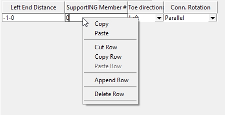
- Handrail add (topic)
- Custom members (topic)
- Hand Rail Setup (sets defauts for first newly added handrail in a Modeling session)
- Show linear measure for handrail in shop bill (setup option)
- Show submaterial mark for posts on handrail member details (setup option)
- Show submaterial mark for rails on handrail member details (setup option)
- Elevation noted at top rail from (setup option)
- Elevation noted at bottom of post (setup option)