v2020 Enhancements
SDS/2 Detailing v2020.00 to v2020i
v2020 Enhancements:
- Connection design
- HOW/2 links
- New and enhanced tools and capabilities:
- Improvements to Job, Fabricator and User and Site Options
- Job Setup
- Fabricator Setup
- New and renamed clip angle configurations ( Fabricator Setup )
- User and Site Options
- Automatic detailing
- Input/Output (including reports)
- Utilities
- Parametrics (v2019 & v2020)
Help style guide changes:
- Hyperlinks other than navigaional hyperlinks are colorized to match their encapsulating text.
- Settings, including hyperlinks to settings, are colorized a shade of red .
- The help topic syntactical and stylistic conventions briefly summarized the new style guide.
Release notes for v2020:
- v2019 & 2020 Release Notes (a searchable list of release notes that summarize PR fixes)
Welded connections can now be designed for HSS horizontal braces (pipe or tube) when, in "
Connection specifications ," you set " Pipe/tube end fitting " to ' Welded '. Formerly, a field welded connection was available for HSS vertical braces, but not for HSS horizontal braces. The gusset fits into a notch in the HSS brace and can be held in place for field welding with one or two field bolts. Setup for these erection bolts is in Fabricator Setup > Member Detailing and Fabrication Options > the " Horizontal Braces " section > " HSS erection bolts " and " Hole type for HSS erection bolt ."
Two new clip angle configurations can now be specified:
Three new "
Connection specifications " options are available for welded-welded clip angles: The options are available for auto-standard, user-defined and beam-edit-window-specified clip angles.
Two new "
Connection specifications " options are available for bent plates: Both options are available for user-defined and beam-edit-window-specified bent plates. " Attachment to supported " is available for auto-standard bent plates.
When you frame an angle, W tee, or HSS rectangular horizontal brace to a wide flange horizontal brace, connection design now creates the same connection as it would if you were to frame to a beam.
Connection design can now design a single-sided vertical brace intersection plate that bolts or welds to the supporting member. The design includes the shape of the plate.
New vertical brace-to-vertical brace connections can now be designed. Also featured in the video below is the ability to create a thru gusset plate for a vertical brace to an HSS round or HSS rectangular column.
YouTube video: Vertical brace bracing to bracing connections. New horizontal brace-to-horizontal brace connections can now be designed.
YouTube video: Bracing to bracing connections, vertical and horizontal. " Tye force "(
) has been added to the "
Loads " leaf of the Beam Edit window for any ASD or LRFD edition. An "
Auto-calculate tying loads " option in Design Criteria permits auto calculation of tying loads.
Both NS and FS horizontal brace gusset plate clip angles used to be stored in a single leaf that was usually named "
HB Conn2 " and sometimes named " HB Conn1 ." Now the NS and FS clip angles can be controlled independently, in leaves named "
NS Clip Conn2 " and "
FS Clip Conn2 ." Welded connections and bolted connections to a beam's top flange are still stored in a leaf named "
HB Conn2 ."
Framing Situation Leafs Containing Relevant Locks HBrc to a beam's web NS Clip Conn2 & FS Clip Conn2 HBrc perpendicular to a beam NS Clip Conn2 & FS Clip Conn2 2-point bracing NS Clip Conn2 & FS Clip Conn2 HBrc to two beams NS Clip Conn1 & NS Clip Conn1
FS Clip Conn2 & NS Clip Conn2HBrc to 2 beams, interposed column NS Clip Conn1 & NS Clip Conn1
FS Clip Conn2 & NS Clip Conn2Both NS and FS vertical brace gusset plate clip angles used to be stored in a single leaf that was named "
Clip Angle 2 ." Now the NS and FS clip angles can be controlled independently, in leaves named "
NS Clip Conn2 " and "
FS Clip Conn2 ."
Framing Situation Leaf with Relevant Locks vertical brace to beam NS Clip Conn2 & FS Clip Conn2 vertical brace to column NS Clip Conn2 & FS Clip Conn2 vbrc to column in beam & column NS Clip Conn1 & FS Clip Conn1 vbrc to beam in beam & column NS Clip Conn2 & FS Clip Conn2 vertical brace 2-point, to a beam NS Clip Conn2 & FS Clip Conn2 vertical brace 2-point, to a column NS Clip Conn2 & FS Clip Conn2 The " Web connection type " setting ' Web plates ' can now get a wide flange vertical brace connection when, in "
Connection specifications ," the " Flange connection type " is ' Flange paddle plates '. Previously, web plates were not available for wide flange vertical braces attached with paddle plates. You still get the failure message " Incompatible web and flange connection " for flange paddle plates with a channel web connection.
End plates can now have up to two bolt columns on each side of the plate. A new end connection failure message, “ End plate with 6 or more bolt columns are not supported ,” has been added.
When a beam's " Input connection type " is ' Bent plate ', "
Connection specifications " now provides an option to " Use paddle plate ." The option can get you a connection when the beam is an HSS/TS that frames to a column.
Beam Edit > the "
Connection type " leaf > "
Use a safety erection seat " now adds a safety seat to an HSS/TS column when the new " Attachment " option is set to ' Welded ' or possibly ' Automatic ' (as opposed to ' Bolted '). When " Attachment " is set to ' Automatic ', the choice made to " Safety erection seat connection to supporting " in Connection Detailing / Fabrication Options determines whether the seat welds or bolts to the column.
When a column's " Input connection type " is ' User base/cap plate ', "
Column plate welds " now provides a ' Solid Groove ' " Weld type ." This option adds square groove welds to attach a base or cap plate to an HSS rectangular (tube) or wide flange column.
For most connection design methods, structural integrity checks are performed if a non-zero entry is made to the " Tie force " load on the Beam Edit or Column Edit window. In pre-v2019 versions, the design method had to be ' EUROCODE3 ' or ' EUROCODE3 UK ' in order for the load entry field to be shown. Also, the name of the option has been changed from " Tie load " to " Tie force ."
Connection design now maintains an index of the spatial relationship between members to improve the speed of member processing, especially in large jobs.
HOW/2 PDF files for v2020 SDS/2 software can be reviewed or downloaded by clicking on a link in the "HOW/2 TITLE" column in following table.
|
HOW/2 TITLE |
HELP |
| ADVANCED BILL OF MATERIAL | Reports > Advanced Bill of Material > the ABM Report window. Another key help page is the ABM Workflow . ( |
| MATERIAL PLATE WASHER OPTIONS | Job Setup > Washer Criteria > press " Material Plate Washers " > the " Material Plate Washer " window. |
| BOLTS, NUTS, AND WASHERS LISTED SEPARATELY IN BILL |
" Bolt/Nut/Washer broken out in BOM " ( Modeling )
" Bolt/Nut/Washer broken out in BOM " ( Drawing Editor ) " Bolt/Nut/Washer broken out in BOM " ( Fabricator Setup ) ( |
| DETAILING ERECTION VIEW UPDATES |
" For detailing " (designating an evu for detailing). " Show for detailing " (filtering erection views that are for detailing). |
| DETAIL VIEWS | Objects > Detail View > Add ( Drawing Editor ) The Detail View Area window. File > Open Detail View Drawing ( |
| MEMBER ADD CATEGORIES |
" (filtering for the F2 selection dialog) ( |
| MEMBER LINE EXTEND | Options > Toolbar Configuration > set " Command Group " to ' Toolbox ' ✶ > Extend Member to Member , Extend Member to Member Adjust Height , Extend All to Column , and Extend All Selected . ( Modeling )
( |
| MISCELLANEOUS
MEMBERS |
Filter for " |
| PDF IMPORT | Interface > Drawing Conversion > " Import Options " > " As Reference Drawing " or " As Job Standard. " Model > Reference Drawing > Reference Drawing Tools > Link .
( |
| SAVE CUSTOM FILTERS | Model > Edit Selection Filter ( Modeling ) and Tools > Edit Selection Filter ( Drawing Editor )
( |
| SECONDARY GIRTS |
Press F2 > check the box " ( |
| SPLIT WINDOWS | View > Tile ( Modeling and Drawing Editor ) " Reuse previous session's tile layout " ( Modeling ) " Reuse previous session's tile layout " ( Drawing Editor ) ( |
| STAIR MEMBER LINE | View > Display Options > " Stair outline " ( Modeling )
" Show stair outline " ( Drawing Editor ) ( |
✶ For more information about Toolbox tools, contact an SDS/2 sales representative
New or improved tools in Modeling :
New miscellaneous members provide superior functionality and ease-of-use characteristics to the legacy miscellaneous members that they can replace.
Bent Plate Flat Bar Rectangular Plate Round Plate Bent Plate Layout Grating Rolled Plate Shear/Threaded Stud Clevis Grating Tread Rolled Section Square Bar Decking Plate Layout Round Bar Turnbuckle
A new ' Toolbox ' command group has been added to toolbar configuration for Modeling . Tools whose icons appear under this command group are free to users whose support accounts are current. Contact an SDS/2 sales representative for more information. To download these tools, log in at https://sds2.com and search (
) for "toolbox".
The ' Toolbox ' command group Bid Wizard Tool export an XLSX file suitable for import into Bid Wizard software. Cost Estimator estimate material and fabrication costs for selected members Dimension Clearance Tool dimension the clearance between two materials Dimension Member Tool dimension the clearance between exact points of members Extend Member to Member extend beams to another beam Extend Member to Member Adjust Height extend beams to another beam and adjust their height Extend All to Column extend beams to a column Extend All Selected extend all selected beams to all selected columns E-Z Beam Release create lift holes for the E-Z Beam Release tool. Galvanizing Check Tool runs checks on galvanized members. STRUMIS Export exports a BSWX file for STRUMIS software Zeman Export export numerical control files with associated data for Zeman fabrication tools Tools relevant to ABM setup, creation, updating and report output can be found in Modeling > Reports > Advanced Bill of Material > the ABM Report window. The ABM Workflow help topic (
) provides a useful overview of these tools. Here are some highlights:
The eye button (
or
or
) for weld " Length " on the Edit Weld(s) window in Modeling sets whether or not a particular weld will have its weld length depicted on its weld symbol when that weld symbol is generated by Detail Members . The original state of the eye button applied to a new weld is whatever choice was made to Job Setup > Weld Design Criteria > " Show weld length on weld symbol " at the time the weld was created. A similar eye button is available on that same Edit Weld(s) window for weld " Size ."
For wide flange, k1 distance has been added to SDS/2 distributed shape files.
Pour Stop is a new type of custom member.
Press F2 > check the box "
Miscellaneous steel " > double-click " Girt (Secondary) " lets you add a girt that runs vertically between two horizontal girts.
Member categories can be turned on/off on the F2 > Member Type Selection window to hide or show members in that window's selection list.
Beam
Column
Vertical Brace
Horizontal Brace
Joist
Embed
Embed Plate
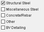

When a category is checked ( ), member types associated with the category will be shown in the list. Multiple categories may be checked.
Material categories can be turned on/off on the F3 > Material Type Selection window to hide or show materials in that window's selection list.
Rolled Section
ExtrudedProfile
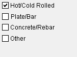

When the " Hot / Cold Rolled " material category is checked, the material types shown in the material selection list are limited to that category.
View > Display Options > " Stair outline ," when checked, shows a stair's stringers, risers, and tread nosings when that stair is in stick form.
View > Set Depth Checking ... or a related toolbar icon or keyboard shortcut can be used as an alternative to the toolbar item or View > Display Options to set an erection view's depth checking limits.
Options > Toolbar Configuration > set " Command Group " to ' Toolbox ' > Extend Member to Member , Extend Member to Member Adjust Height , Extend All to Column , and Extend All Selected are new tools that extend beams that you select to other beams or columns. For such operations, these are convenient alternatives to Move/Stretch and Move/Stretch Include Material tools. For more information about Toolbox tools, contact an SDS/2 sales representative.
Options > Toolbar Configuration > set " Command Group " to ' Toolbox ' > Cost Estimator is also new. This tool conveniently provides tables of estimated costs for bolts, welds, holes, and materials in members that you select in the 3D model. Optionally, it can output those tables to an .xlsx file that is compatible with Microsoft Excel and other programs.
The " Allow washers on bearing shoe slots " option in the Joist Edit window adds material plate washers on bearing shoe slots for bolted joist bearing and seated connections. When set to ' Automatic ', the choice made to the same-named option in the Fabricator Setup > Joist Setup window will be used.
Model > Reference Drawing > Reference Drawing Tools > Link lets you import .dxf, .dxb, .dwg, .dgn or .pdf files as reference drawings in Modeling . Once linked, a reference drawing is created that contains the externally-linked drawing, and that reference drawing is then added to your 3D model in the same manner as it is when you use the " Add Reference Drawing " command.
Model > Reference Drawing > Reference Drawing Tools > Scale Drawing Single Axis and Scale Drawing Dual Axis scales detail, job standard detail, reference drawing or 2D erection view drawings after you " Add " or " Link " them in Modeling .
Modeling's Select One Erection View dialog now features selection filtering for "Primary" "Secondary" etc. (
)
New tools and capabilities in the Drawing Editor :
A new Objects > Detail View > Add tool (
) has been added to Drawing Editor . The tool allows you to select an area within a drawing to be magnified and, on the Detail View Area window, to specify a magnification. The result is a framed and magnified detail of the selected area with a callout that is similar to the callout on a section view.
Objects > Sheet Items selects detail view objects. When you Edit the sheet item, you can choose ' Detail View ' as the " Sub-drawing style " to select an item's detail view instead of its viewport.
If you File > Open Detail View Drawing from the original creating parent drawing of a detail view (or right-click to accomplish the same) (
), that drawing's annotations can be edited to modify the magnified detail view area that is shown on the original creating parent drawing. The parent drawing can be a member detail, a submaterial, or an erection view drawing.
File > Synchronize Detail View Drawings (
) can be used to update a detail view with changes made in the original member detail or 2D erection view or submaterial detail which that detail view was created from. Otherwise, once created, the detail view does not automatically reflect changes made due to that drawing being user-modified or redetailed. The original member detail or other drawing that the detail view was created from needs to be your current drawing when you use this tool.
Objects > Sheet Items now selects detail view objects. When you Edit a sheet item other than a job standard detail, you can choose ' Detail View ' as the " Sub-drawing style " to select a detail view instead of a viewport. A detail view -- a magnified detail of an area framed by a callout -- displays a special drawing that can be modified and scaled independently from the drawing it is placed in.
The Weld Input window in Drawing Editor now has options to enable the " Stitch weld " supplementary symbol and change the " Length " and " Spacing " text that the weld object displays. These options correspond to those in the Add Weld(s) and Edit Weld(s) windows in Modeling .
Setting a label 's " Border " to ' Slot ' will circumscribe the label with a rectangle that has rounded ends. Your choice of " Border line style " can be applied to the border.
Drawing Editor > Tools > Scale Drawing Single Axis and Scale Drawing Dual Axis scales reference drawings.
Various Erection View Cleanup enhancements have been added:
Modeling and Drawing Editor windows can be split into separate View > Tiles (
) within the same session. Each tile is resizable, supports editing operations, and can display its own view. In Modeling , for example, you can have one tile show a plan view and another tile show an isometric view. User and Site Options > Modeling > " Reuse previous session's tile layout " and User and Site Options > Drawings > " Reuse previous session's tile layout " are options for extending your last tile layout to the next Modeling or Drawing Editor session.
On the Bolt Edit window in Modeling , " Bolt/Nut/Washer broken out in BOM " (
) (when checked) breaks apart the selected bolt(s) and each bolt's nuts and washers as separate line items in the bill of material. The option does not apply, however, when " Tension control (TC) " is enabled. A same-named option is also available in the Drawing Editor . For both instances of the same-named option, the default choice (checked or not checked) comes from Fabricator Setup > Bolt Detailing/Fabrication Options > " Bolt/Nut/Washer broken out in BOM ."
Model > Set Selection Filter (in Modeling) and Tools > Set Selection Filter (Drawing Editor) can " Save " custom selection filters. Also, Model > Edit Selection Filter (in Modeling ) and Tools > Edit Selection Filter ( Drawing Editor ) can be used to edit and save these selection filters.
SDS/2 Concrete and Concrete Setup :
Concrete slabs and elevation walls now have a " Square edges " option. When checked, the edges of a sloped slab will be cut perpendicularly to the top of the slab rather than perpendicularly to the model's plan view, and the edges of an elevation wall will be cut parallel to the plan view.
Pad footing member details now show top and bottom footing elevations and rebar run callouts.
" Show weld length on weld symbol " has been moved to Job Setup > Weld Design Criteria from Fabricator Setup > Detailing Symbol Options because the option no longer applies directly to auto detailing. Whether or not weld length is shown on a weld symbol is set when the weld is created in Modeling and can be overridden on the Edit Weld (s) window by setting the weld " Length " to be shown (
) or not shown (
). Auto detailing then applies the choice that is made in Modeling .
The default location for end plate haunches can now be configured using the Moment Plate Design Criteria setup option " Default haunch location ." You can instruct connection design to locate the haunch on the ' Top , ' ' Bottom , ' or in ' Both ' locations. The choice is used when the " Haunch location " is set to "
Auto " in the Beam Edit window or in Job Setup > User Defined Connections . This option is only enabled when the " Connection design method " is ' Eurocode ' or ' EUROCODE 3 UK '.
New Design Criteria setup options have been added to limit the allowable loads for intersecting horizontal and vertical braces: These are " Percent of allowable tension load for intersection horizontal braces " and " Percent of allowable compression load for intersection horizontal braces " and " Percent of allowable tension load for intersection vertical braces " and " Percent of allowable compression load for intersection vertical braces ."
A new option named " Maximum gap for a single filler " has been added to the Flange Plate Gaps setup window. If the gap in a bolted moment connection with slip critical bolts is greater than this maximum gap, connection design assumes that multiple fillers will be used.
The Base/Cap Plate Schedule has a new column for " Weld type " (' Fillet ' or ' Square Groove ').
Job Setup > Washer Criteria > press the " Material Plate Washers " button > the " Material Plate Washer " window lets you configure plate washers for different bolt diameters.
Job Setup > Event Logging Setup now provides options for ABM event logging.
The Fabricator Setup window ABM Report Layout has been moved to the ABM Report window, which in Modeling can be opened by choosing Reports > Advanced Bill of Material . It remains associated with your current Fabricator, even though it is no longer found in Fabricator Setup .
Similarly, the new ABM Qualifiers window is associated with your current Fabricator, even though it is accessed from the ABM Report window. It's appearance is similar to the Fabricator Setup > ABM Report Criteria window found in pre-v2020 SDS/2 software. The window lets you define the members and materials for which you want "
ABM " check box automatically checked when they are added. The members and materials for which "
ABM " is checked are qualified for inclusion in the ABM.
A " Cope radius " option has been added to Fabricator Setup > Member Detailing/Fabricator Options > the " Beams " section. It sets the default for members with ' Cope plain ' operations.
Horizontal HSS braces (pipe or tube) with ' Welded ' end fittings have two new configuration options in the " Horizontal Braces " section of the Member Detailing/Fabricator Options setup window. Settings made to the " HSS erection bolts " option instruct connection design to hold a brace in place with ' One ' erection field bolt, ' Two ' bolts, or ' None '. The choice will be used when " Erection bolts " is set to ' Automatic ' in the Horizontal Brace Edit window. The selection for the " Hole type for HSS erection bolts " option instructs connection design to use ' Standard round ', ' Short slot ', ' Oversize ', ' Long slot ', or ' User slot (#1 or #2) ' holes when field bolts are used.
In the Bolt Detailing/Fabrication Options window, you may check " Bolt/Nut/Washer broken out in BOM " (
). Choose this option if you job requires the bolts, nuts and washers to be broken out as separate line items in the bill of material, or if you need a total count of nuts and washers. It sets the default for " Bolt/Nut/Washer broken out in BOM " (
) on Bolt Edit windows in Modeling and in the Drawing Editor .
An " Allow washers on bearing shoe slots " option has been added to the Fabricator Setup > Joist Setup window. When this option is checked, connection design adds material plate washers on bearing shoe slots for bolted joist bearing and seated connections. This choice will be used when the same-named option is set to ' Automatic ' in the Joist Edit window in Modeling .
When the "
Use a safety erection seat " option in the Beam Edit window is checked, the clip angle " Section size " under the "
Safety seat " leaf may now use the " Seat angle section size " that you enter on the Connection Detailing / Fabrication Options window. You also may choose either a ' Bolted ' or a ' Welded '. " Safety seat connection to supporting " on this setup window, and, if the entered " Seat angle section size " has legs of unequal length, choose to " Attach long leg to " either the ' Supported ' or the ' Supporting ' member. Where the connection is bolted, you can enter a " Gage on leg to supported member " and another distance to the " ...supporting member ."
On the Connection Detailing / Fabrication Options window, you may choose " Do weld prep on moment flange plates " (
). This option instructs connection design to bevel moment plates for groove welds when such welds are generated for system designed bolted moment flange plates.
New and renamed clip angle configurations :
In Fabricator Setup > Standard Fabricator Connections , clip angle configurations are now classified as All-Bolted , Bolted/Welded and All-Welded . The names of these configurations are as follows. The two All-Welded configurations at the bottom are entirely new.
| All-Bolted Clip Angle Configurations |
| Heavy Gage OSL All-Bolted Clip Angles | |
|
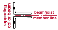
Heavy gage bolted-bolted double clip angles are designed when ' Heavy ', ' Bolted ' (to supported), ' Bolted ' (to supporting), and ' Supported ' (or ' Supporting ') are specified for auto standard , user defined or beam-edit-window-specified clip angles. |
| Wide Gage OSL All-Bolted Clip Angles | |
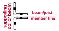 |
Wide gage bolted-bolted double clip angles are designed when ' Wide Gage ', ' Bolted ' (to supported), ' Bolted ' (to supporting), ' Both ' (sides of web) and ' Supported ' (or ' Supporting ') are specified. |
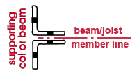
| Narrow Gage OSL All-Bolted Clip Angles | |
| Narrow gage bolted-bolted double clip angles are designed when ' Narrow Gage ', ' Bolted ' (to supported), Bolted (to supporting), ' Both ' (sides of web), and shop attach to ' Supported ' (or ' Supporting ') are specified. |
|
| Single Clip Angles All-Bolted |

|
| A single bolted-bolted clip angle that shop attaches to the supporting or supported member is designed when ' Narrow Gage ' (or ' Wide Gage '), ' Bolted ' (to supported), ' Bolted ' (to supporting), ' Near Side ' (or ' Far Side ' of web), and shop attach to ' Supported ' (or ' Supporting ') are specified. |
| Bolted/Welded Clip Angle Configurations |
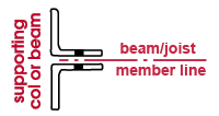
| Bolted/Welded: Double Angle: Welded OSL | |
| Bolted/welded double clip angles that weld to the supporting beam or column are designed when ' Narrow Gage ' (or ' Wide Gage '), ' Welded ' (to supporting), ' Bolted ' (to supported), ' Both ' (sides of web), Supporting (or ' Supported ') are specified for auto standard, user defined or beam-edit-window-specified clip angles. |
|
| Bolted/Welded: Single Angle, Welded OSL |

|
| A single bolted/welded clip angle that welds to the supporting beam or column is designed when ' Narrow Gage ' (or ' Wide Gage '), ' Welded ' (to supporting), ' Bolted ' (to supported), ' Near Side ' (or ' Far Side ' of web), and shop attach to Supporting (or ' Supported ') are specified. |
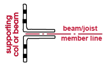
| Bolted/Welded: Heavy Gage OSL | |
| Heavy gage bolted/welded double clip angles that bolt to the supporting beam or column are designed when ' Heavy Gage ', ' Bolted ' (to supporting), ' Welded ' (to supported) and shop attach to ' Supporting ' (or ' Supported ') are specified. |
|
|
||||
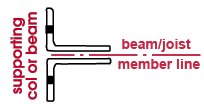
| Bolted/Welded: Narrow Gage OSL | |
| Narrow gage bolted/welded double clip angles that bolt to supporting beam or column are designed when ' Narrow Gage ', ' Bolted ' (to supporting), ' Welded ' (to supported), ' Both ' (sides of web), and shop attach to ' Supporting ' (or ' Supported ') are specified. |
|
| Bolted/Welded: Single Angle, Bolted OSL |

|
| A single bolted/welded clip angle that bolts to the supporting member (beam or column) is designed when ' Narrow Gage ' (or ' Wide Gage '), ' Bolted ' (to supporting), ' Welded ' (to supported), Near Side (or ' Far Side ' of web), and shop attach to ' Supporting ' (or ' Supported ') are specified. |
| All-Welded Clip Angle Configurations |
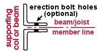
| All-Welded: Attached to Supporting Member | |
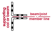
| Welded-welded double clip angles that shop weld to the supporting member (beam or column) are designed when ' Supporting ' (shop attached to), ' Welded ' (to supported) and ' Welded ' (to supporting) are specified for auto standard , user defined or beam-edit-window-specified clip angles. |
|
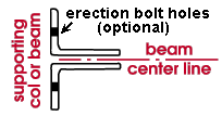
| All-Welded: Attached to Supported Member | |
| Welded-welded double clip angles that shop weld to the supported beam are designed when ' Supported ' (shop attached to), ' Welded ' (to supported) and ' Welded ' (to supporting) are specified. |
|
In pre-v2020 versions of SDS/2 software, the User and Site Options window was named User Options . All options on this new version of the window except those under the " Site " section are user options . Options under the " Site " section are all site options . Options related to the Drawing Editor are under the " Drawing " section. Options related to Modeling are under the " Modeling " section.
To prevent the addition of graphic objects to shortened drawings in the Drawing Editor , a new " Always ask to unshorten drawings before adding objects " option has been added to User and Site Options > Drawings . When the option is checked and you begin to add an object to a shortened drawing, a dialog box lets you press " Continue " to unshorten the drawing automatically.
User and Site Options > Modeling > " Reuse previous session's tile layout " and Drawings > " Reuse previous session's tile layout " are new options related to tiles. When checked, these options preserve your window tiles for reuse in your next Modeling or Drawing Editor session. Related tile options are User and Site Options > General > " Hover tile color " and " Active tile color ."
Site > " Show legacy miscellaneous member in member add screen " lets you hide legacy miscellaneous members from the Prompt for Member Type window selection list, thus helping to prevent such members from being added to the model. Best practice is add the new miscellaneous members instead of the legacy miscellaneous members.
Site > " Show Girt (legacy) in member add screen " lets you hide the legacy girt from the Prompt for Member Type window selection list. As miscellaneous members, it is best practice avoid adding the legacy member and add the new girt member instead.
Modeling > Prompt to temporarily turn off Z-filtering before some tools applies to Model > Member > Copy and Model > Member > Move/Stretch .
Elevation callouts are generated on concrete pad footing details when the latest detailing templates are used. These new templates can be found in the
detailing/SDS2 folder that is maintained in the data directory for your current version of SDS/2 Detailing software. The Copy Detailing Templates utility can be used to update your templates.
The new ' Hidden ' " Concrete Member Style " option on the Detail Erection View Defaults window instructs erection view detailing to hide concrete material.
Placement format options for cast in place column " Vertical bars " and cast in place column " Ties " have been added to Concrete Setup > Rebar Schedule Placements > the Column tab. The " Placement note " for rebar shape material placed in cast in place columns can be auto-populated with an entry to one of these fields. The placement note can also appear in reports made with Report Writer and in custom reports .
Automatic detailing of erection views has been enhanced:
The new ABM Report window lets you configure -- on a single window -- formatting and classes of items to include in an Advanced Bill of Material . To open this window in Modeling or Drawing Editor , choose Reports > Advanced Bill of Material . The window can also be opened from Home > " Reports " heading > the " System " tab > ABM Report . The ABM Workflow help page can help you get started using the new ABM.
An alternative to doing a StruMIS Transfer , the new StruMIS BIMReview Export tool produces a BSWX file suitable for use in the StruMIS BIMReview program. This tool can be configured on the Command Plugin Setup window.
Drawing Conversion now gives you the option to bring PDF files into SDS/2 programs as reference drawings or as job standard details. Formerly, only .dxf, .dxb, .dwg or .dgn files could be converted.
The Fortosi Export tool, which produces an IFC file suitable for the Fortosi truck load planning program, is now available to SDS/2 Detailing users. To add the icon to your toolbar in Modeling , choose Options > Toolbar Configuration > select the " Command group " called ' Model ' > drag the Fortosi Export icon to your toolbar.
An option has been added to Verify and Fix to " Regenerate the spatial index and journal ." This index and journal is used by connection design and other functions.
Parametrics (includes PRs from v2018):
PR 22429 A new attribute "custom_member_type" is defined on member objects in advanced selection. The value of this attribute is a string that represents the type of the member; it can either be one of the strings defined for built-in member types (such as "Vertical brace") or the string defined by a custom member type (such as "AnchorRod"). To find out the string value for a specific custom member, refer to that custom member's documentation. (v2018)
PR 39777 When " member .MultiMemberLocate" is canceled by the user, Python will now receive a dialog.ResponseNotOK exception. In previous versions, the result was "SystemError: error return without exception set". (v2018)
PR 41875 The SDS/2 python prompt now has an auto complete feature. When a user starts to type something in the prompt, a list of possible completions will be displayed. Users may select completions from this list. (v2018)
PR 42693 Fixed a bug in python dialogs with Modified rules running before every widget had been given a value, and even before some widgets were ready to start receiving new values (so user code couldn't reliably call Set() in a Modified callback). (v2018)
PR 43358 In the Python API's, Proxies defined in Designable .Proxies now have an OnSolidsException method which allows subclasses to have custom exception handling when the underlying solids operation is called and generates an exception. (v2018)
PR 43832 Cold form section bends have been exposed via the shape parametric module. (v2018)
PR 44622 In the Python API ( sds2.utility ), Components can now be edited during GadgetMember multi-edit. GadgetComponents can opt out by overriding MultiCreateUIFoldID() and return None. Otherwise, GadgetMember will group all the components of the same class and MultiCreateUIFoldID() together during multiedit. The default GadgetComponent.MultiCreateFoldID implementation is to return the fully qualified class name of the component. (v2018)
PR 44764 Fixed a bug in the Python API where the Designable package failed to find material created by a Processable that was broken apart into a linked miscellaneous member. (v2018.09)
PR 44871 In the Python API fixed a bug in Component .ReplaceLiveComponentsWithCopy that prevented components from being saved. (v2018.09)
PR 44894 In the Python API, users can browse a subset of the shape file. See help( SelectionDialog .RunMaterialFileSelectionDialog) for more information. The dialog .choose_file.ChooseMtrl can support similar functionality via attributes for a list of shapes and browser title. (v2018)
PR 45100 Calling GetPolygons() on a MaterialBase material that is not yet in the database now returns None if the material does not yet have polygons. (v2018)
PR 45178 In the Python API, non-navigation tools will be disabled during Layout3D .get_Layout3D and the default Component .Component.SetReferencePointForMemberUI() implementation. (v2018)
PR 45284 Fixed a regression in the Python Designable .Proxies API where field bolts were incorrectly being added as shop bolts. (v2018.09)
PR45397 Detail sheet auto loading through Drawing .SheetAutoLoad has been fixed. Previously a python warning would occur stating no sheet outline specified. (v2018)
PR 45463 The Python API Intersect3D can be used to create SimpleShapes for a member's local bounding box. sds2.iterators and sds2.lists introduce functions for finding members and materials based on the Intersect3D module. model .DoPolygonsIntersect leverages the speed optimizations in Intersect3D. sds2.obj introduces convenience functions for visualizing bounding boxes. (v2018)
PR 45883 Custom material surface area is now customizable by overriding the CalculateSurfaceArea() method of MaterialBase . (v2018)
PR 46240 It is now possible to set routings above 40 via model .ChangeOneMaterial. (v2018)
PR 46318 During process, plugins can add views to the misc. members that they create via the BreakApartMaterials API. (v2018)
PR 46769 The Python MaterialBase API allows custom materials to be set to dummy material via the 'is_dummy' attribute. (v2018)
PR 46959 The following Member Detailing/Fabrication Options have been exposed via the parametric API fab modlule:
Vertical braces:
1. HSS notch width clearance: vb_hss_notch_width_clear
2. HSS notch radius: vb_hss_notch_radius
3. Automatic HSS notch radius: auto_vb_hss_notch_radius
4. Intersection gusset notch preparation: vb_hss_notch_prepColumns/ Shear thru plates:
1. HSS notch width clearance: shear_hss_notch_width_clear
2. HSS notch radius: shear_hss_notch_radius
3. Automatic HSS notch radius: auto_shear_hss_notch_radius (v2018)PR 46960 The Python dialog .text.Text widget will return an empty string if its initial value was empty. Previously, a newline character was returned due to the nature of the underlying control. The side effect of this is screens that utilize this widget such as custom properties will not introduce a change to the stored data by simply opening and closing the screen. As a specific example, custom properties that flag the member for detailing or piecemarks will not flag the member by simply opening and closing custom properties when the member's custom properties had not previously been visited. (v2020)
PR 46989 Python Layout3D objects may have their "remove_bad_points" attribute set to False to avoid automatically removing collinear and duplicate points. (v2020)
PR 47091 Fixed a bug in the list variant of the set function for variable spacing lockables in the sds2.lockable module. The bug caused the list variant to be a no op. (v2020)
PR 47458 In the Python API, custom members can set left_rotation and right_rotation for end rotations. Setting the left_rotation to the member's rotation and setting right_rotation to the opposite rotation will help ensure rotated custom members end up with the same piecemark. (v2020)
PR 47473 In the member module in parametrics, when setting the connection type SDS/2 will now choose sensible defaults for that connection type. This may produce different connections for parametrics that add new members, with connection set, but don't set all of the connection specification. The options chose should match those we pick when setting the connection type on the member edit screen. (v2020)

